Full Text Searchable PDF User Manual
28
FOR HELP OR ADVICE ON THIS PRODUCT PLEASE CONTACT YOUR DISTRIBUTOR,
OR SIP DIRECTLY ON:
TEL: 01509500400
EMAIL: sales@sip-group.com or technical@sip-group.com
www.sip-group.com
Ref: 040817
Please dispose of packaging for the product in a responsible
manner. It is suitable for recycling. Help to protect the
environment, take the packaging to the local amenity tip
and place into the appropriate recycling bin.
Never dispose of electrical equipment or batteries in with
your domestic waste. If your supplier offers a disposal facili-
ty please use it or alternatively use a recognised re-cycling
agent. This will allow the recycling of raw materials and help
protect the environment.
1
Please read and fully understand the instructions in this manual
before operation. Keep this manual safe for future reference.
05703, 05705 & 05707
T800 / T1400 / T1600
Arc Inverter Welder
2
27
Declaration of Conformity
We
SIP (Industrial Products) Ltd
Gelders Hall Road
Shepshed
Loughborough
Leicestershire
LE12 9NH
England
As the manufacturer's authorised representative within the EC
declare that the
SIP T800 ARC Inverter Welder - SIP Part. No. 05703
T1400 ARC Inverter Welder - SIP Part. No. 05705
T1600ARC Inverter Welder - SIP Part. No. 05707
Conforms to the requirements of the following directive(s), as indicated.
2014/35/EU
Low Voltage Directive
2014/30/EU
EMC Directive
2011/65/EU
RoHS Directive
Signed: …………………………………...
Mr P. Ippaso - Director - SIP (Industrial Products) Ltd
Date: 23/07/2017.
And the relevant harmonised standard(s), including
DECLARATION OF CONFORMITY
EN 60974-1:2012
EN 60974-10:2014+A1:2015
26
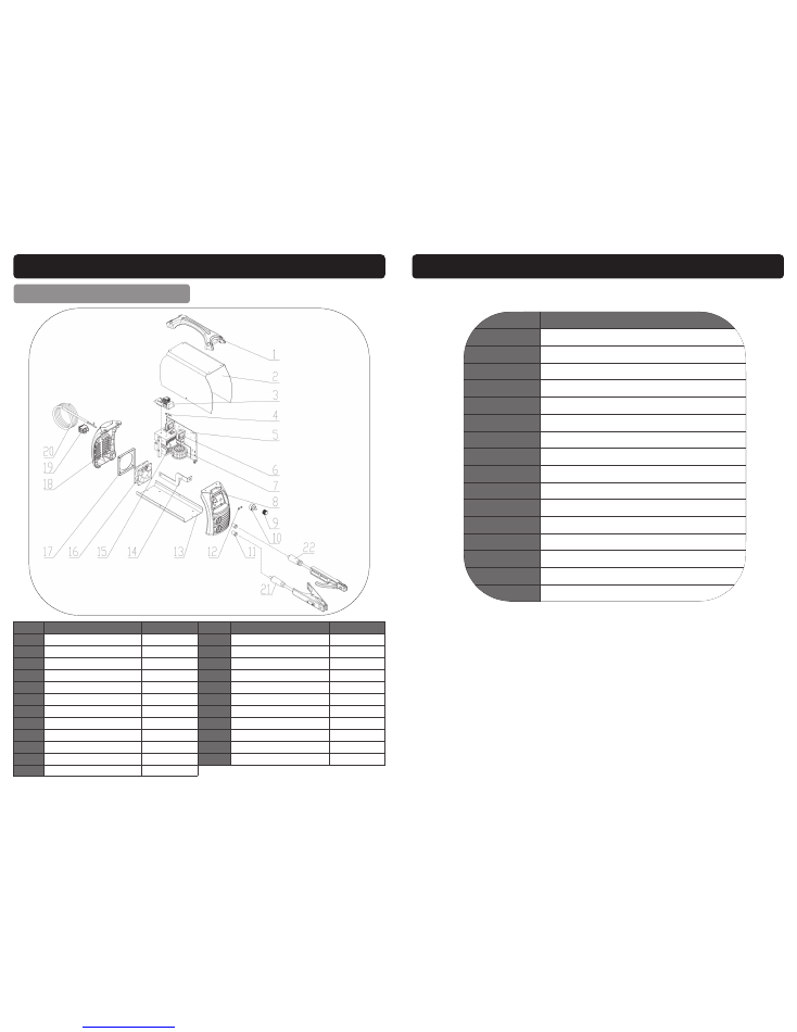
EXPLODED DRAWING / PARTS LIST
T1600 (05707)
Ref. No.
Description
Sip Part No. Ref. No.
Description
Sip Part No.
1.
Handle
WE07-00051
13.
Chassis
WE07-00063
2.
Cover
WE07-00079
14.
Positive Output Busbar
WE07-00076
3.
EMC Board
WE07-00080
15.
Electrolytic Capacitor
WE07-00081
4.
NTC Resistance
WE07-00054
16.
Fan
WE07-00077
5.
Main Control PCB
WE07-00081
17.
Fan Fixing Plate
WE07-00067
6.
Power Transformer
WE07-00056
18.
Plastic Rear Cover
WE07-00068
7.
Main Transformer
WE07-00075
19.
Main On/Off Switch
WE07-00069
8.
Front Plastic Panel
WE07-00058
20.
Mains Lead
WE07-00082
9.
Potentiometer knob
WE07-00059
21.
Earth Lead
c/w
Clamp
WE07-00037
10.
Potentiometer
WE07-00060
22.
Welding cable
c/w
Electrode
Holder
WE07-00036
11.
Dinse Socket
WE07-00061
N/A
Front Cover Label
WE07-00083
12.
LED Holder
WE07-00062
3
CONTENTS
Page No. Description
4.
Safety Symbols Used Throughout This Manual
4.
Safety Instructions
11.
Electrical Connection
13.
Guarantee
13.
Contents and Accessories
14.
Technical Specification
15.
Getting to Know Your Inverter Welder
16.
Operating Instructions
20.
Maintenance
21.
Troubleshooting
22.
Wiring Diagram - T800 (05703)
23.
Wiring Diagram - T1400 (05705) / T1600 (05707)
24.
Exploded Drawing / Parts List T800 (05703)
25.
Exploded Drawing / Parts List T1400 (05705)
26.
Exploded Drawing / Parts List T1600 (05707)
27.
Declaration of Conformity

4
When using your inverter welder, basic safety precautions should always be followed
to reduce the risk of personal injury and / or damage to the inverter welder.
Read all of these instructions before operating the inverter welder and save this user
manual for future reference.
The inverter welder should
not
be modified or used for any application other than that
for which it was designed.
This inverter welder was designed to supply electric current for ARC and TIG welding.
If you are unsure of its relative applications do not hesitate to contact us and we will
be more than happy to advise you.
Before each use of the inverter welder always check no parts are broken and that no
parts are missing.
Always operate the inverter welder safely and correctly.
KNOW YOUR INVERTER WELDER:
Read and understand the owner's manual and labels
affixed to the inverter welder. Learn its applications and limitations, as well as the po-
tential hazards specific to it.
KEEP WORK AREA CLEAN AND WELL LIT:
Cluttered work benches and dark areas invite
accidents. Floors must not be slippery due to oil, water or sawdust etc.
DO NOT USE THE INVERTER WELDER IN DANGEROUS ENVIRONMENTS:
Do not use the
inverter welder in damp or wet locations, or expose it to rain. Provide adequate space
surrounding the work area. Do not use in environments with a potentially explosive at-
mosphere.
KEEP CHILDREN AND UNTRAINED PERSONNEL AWAY FROM THE WORK AREA:
All visitors
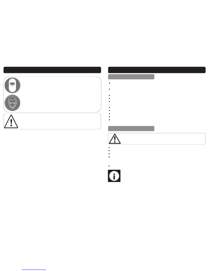
SAFETY SYMBOLS USED THROUGHOUT THIS MANUAL
SAFETY INSTRUCTIONS
Important:
Please read the following instructions carefully,
failure to do
so could lead to serious personal injury and / or damage to the invert-
er welder.
Danger / Caution:
Indicates risk of personal injury and/or the possibility of
damage.
Warning:
Risk of electrical injury or damage!
Note:
Supplementary information.
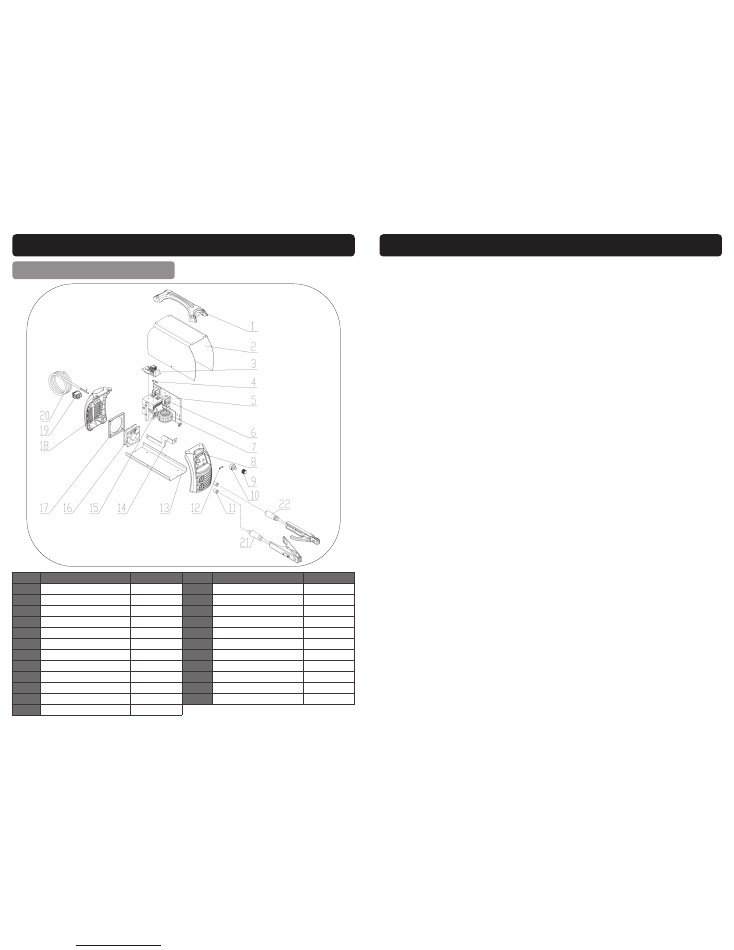
25
EXPLODED DRAWING / PARTS LIST
T1400 (05705)
Ref. No.
Description
Sip Part No. Ref. No.
Description
Sip Part No.
1.
Handle
WE07-00051
13.
Chassis
WE07-00063
2.
Cover
WE07-00072
14.
Positive Output Busbar
WE07-00076
3.
EMC Board
WE07-00073
15.
Electrolytic Capacitor
WE07-00065
4.
NTC Resistance
WE07-00054
16.
Fan
WE07-00077
5.
Main Control PCB
WE07-00074
17.
Fan Fixing Plate
WE07-00067
6.
Power Transformer
WE07-00056
18.
Plastic Rear Cover
WE07-00068
7.
Main Transformer
WE07-00075
19.
Main On/Off Switch
WE07-00069
8.
Front Plastic Panel
WE07-00058
20.
Mains Lead
WE07-00070
9.
Potentiometer knob
WE07-00059
21.
Earth Lead
c/w
Clamp
WE07-00037
10.
Potentiometer
WE07-00060
22.
Welding cable c/w Electrode Holder
WE07-00036
11.
Dinse Socket
WE07-00061
N/A
Front Cover Sticker
WE07-00078
12.
LED Holder
WE07-00062
24
EXPLODED DRAWING / PARTS LIST
T800 (05703)
Ref. No.
Description
Sip Part No. Ref. No.
Description
Sip Part No.
1.
Handle
WE07-00051
13.
Chassis
WE07-00063
2.
Cover
WE07-00052
14.
Positive Output Busbar
WE07-00064
3.
EMC Board
WE07-00053
15.
Electrolytic Capacitor
WE07-00065
4.
NTC Resistance
WE07-00054
16.
Fan
WE07-00066
5.
Main Control PCB
WE07-00055
17.
Fan Fixing Plate
WE07-00067
6.
Power Transformer
WE07-00056
18.
Plastic Rear Cover
WE07-00068
7.
Main Transformer
WE07-00057
19.
Main On/Off Switch
WE07-00069
8.
Front Plastic Panel
WE07-00058
20.
Mains Lead
WE07-00070
9.
Potentiometer knob
WE07-00059
21.
Earth Lead
c/w
Clamp
WE07-00037
10.
Potentiometer
WE07-00060
22.
Welding cable c/w Electrode Holder
WE07-00036
11.
Dinse Socket
WE07-00061
N/A
Front Cover Sticker
WE07-00071
12.
LED Holder
WE07-00062
5
SAFETY INSTRUCTIONS….cont
should be kept at a safe distance from the work area.
STORE THE INVERTER WELDER SAFELY WHEN NOT IN USE:
The inverter welder should be
stored in a dry location and disconnected from the mains supply, and out of the
reach of children.
USE SAFETY CLOTHING / EQUIPMENT:
Use a CE approved welding mask at all times with
the correct shade of filter lens. A fume extractor should be used particularly where
there is little or no ventilation.
PROTECT YOURSELF FROM ELECTRIC SHOCK:
When working with the inverter welder,
avoid contact with any earthed items (e.g. pipes, radiators, hobs and refrigerators,
etc.). It is advisable wherever possible to use an RCD (residual current device) at the
mains socket.
STAY ALERT:
Always watch what you are doing and use common sense. Do not oper-
ate the inverter welder when you are tired or under the influence of alcohol or drugs.
DISCONNECT THE INVERTER WELDER FROM THE MAINS SUPPLY:
When not in use and
before servicing.
AVOID UNINTENTIONAL STRIKING:
Make sure the main switch is in the
Off
position be-
fore connecting the inverter welder to the mains supply.
NEVER LEAVE THE INVERTER WELDER CONNECTED WHILST UNATTENDED:
Turn the invert-
er welder off and disconnect it from the mains supply between jobs. Do not leave the
inverter welder connected to the mains supply if no more welding is to be done.
DO NOT ABUSE THE MAINS LEAD:
Never attempt to move the inverter welder by the
mains lead or pull it to remove the plug from the mains socket. Keep the mains lead
away from heat, oil and sharp edges. If the mains lead is damaged, it must be re-
placed by the manufacturer or its service agent or a similarly qualified person in order
to avoid unwanted hazards.
All
extension cables must be checked at regular intervals
and replaced if damaged.
CHECK FOR DAMAGED PARTS:
Before every use of the inverter welder, any damage
found should be carefully checked to determine that it will operate correctly, safely
and perform its intended function. Any damaged, split or missing parts that may af-
fect its operation should be correctly repaired or replaced by an authorised service
centre unless otherwise indicated in this instruction manual.
KEEP ALL COVERS / PANELS IN PLACE:
Never operate the inverter welder with any co-
vers / panels removed, this is extremely dangerous.
MAINTAIN THE INVERTER WELDER WITH CARE:
Keep the earth clamp and electrode
holder clean for the best and safest performance.
USE ONLY RECOMMENDED ACCESSORIES:
Consult this user manual, your distributor or
SIP directly for recommended accessories. Follow the instructions that accompany the
accessories. The use of improper accessories may cause hazards and will invalidate
any warranty you may have.
SECURE THE WORKPIECE:
Always use welding clamps to secure the workpiece. This
frees up both hands to operate the inverter welder correctly.
DO NOT OVERREACH:
Keep proper footing and balance at all times.
USE THE RIGHT TOOL:
Do not use the inverter welder to do a job for which it was not
6
SAFETY INSTRUCTIONS….cont
designed.
DO NOT OPERATE THE INVERTER WELDER IN EXPLOSIVE ATMOSPHERES:
Do not use the
inverter welder in the presence of flammable liquids, gases, dust or other combustible
sources. Inverter welding will create sparks which can ignite the dust or fumes.
DO NOT EXPOSE THE INVERTER WELDER TO RAIN OR USE IT IN WET CONDITIONS:
Water
entering the inverter welder will greatly increase the risk of electric shock.
HAVE YOUR INVERTER WELDER REPAIRED BY A QUALIFIED PERSON:
The inverter welder is
in accordance with the relevant safety requirements. Repairs should only be carried
out by qualified persons using original spare parts, otherwise this may result in consid-
erable danger to the user.
Stop operation immediately if you notice anything abnormal.
Always disconnect the plug from the mains supply before cleaning or servicing
etc.
Be alert at all times, especially during repetitive, monotonous operations; Don't
be lulled into a false sense of security.
Use of improper accessories may cause damage to the inverter welder and
surrounding area as well as increasing the risk of injury.
Do not
modify the inverter welder to do tasks other than those intended.
To avoid injury, the workpiece should never be held with bare hands; The work-
piece will become hot during normal welding operations, and stay hot for a
period after the weld is complete.
Appropriate personal protective equipment
must
be worn and
must
be de-
signed to protect against all hazards created. Severe permanent injury can re-
sult from using inappropriate or insufficient protective equipment - Eyes in par-
ticular are at risk.
The work should be clamped firmly whilst welding, If its loose it could result in
personal injury or damage to the machine or item that is being welded.
Do not
attempt any repairs unless you are a competent electrician or engineer.
Ensure that the machine is connected to the correct supply voltage and pro-
tected by a fuse or circuit breaker of the recommend rating.
Never
allow the earth clamp and electrode holder to come into contact with
each other.
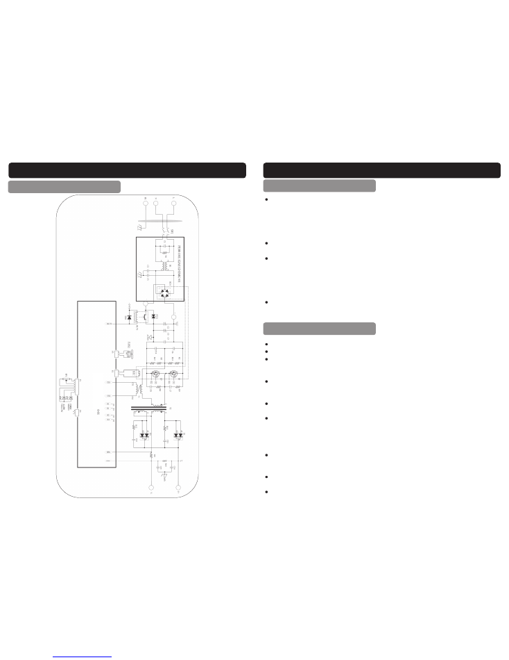
23
WIRING DIAGRAM
T1400 (05705) & T1600 (05707)
22
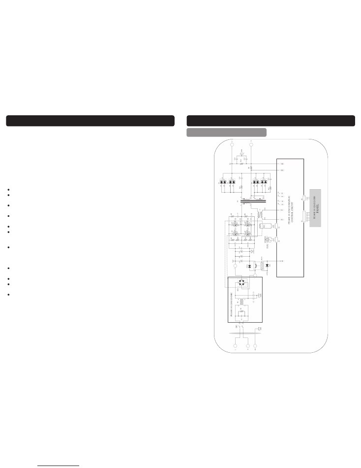
WIRING DIAGRAM
T800 (05703)
7
SAFETY INSTRUCTIONS….cont
Keep your body and clothing dry. Never work in a damp area without ade-
quate insulation against electrical shock, stay on a dry duck board, or rubber
mat when dampness or sweat can not be avoided. Sweat, sea water or mois-
ture between the body and an electrically ’hot’ part or grounded metal reduces
the body surface electrical resistance enabling dangerous and possibly lethal
currents to flow through the body.
Never
allow live metal parts to touch bare skin or any wet clothing, be sure
welding gloves are dry.
Before welding, check for continuity; Be sure the earth clamp is connected to
the workpiece as close to the welding areas as possible. Grounds connected to
building frame work or other remote locations from the welding area reduce
efficiency and increase the potential electric shock hazard. Avoid the possibility
of the welding current passing through lifting chains, crane cables or various
electric paths.
Frequently inspect leads for wear, splits, cracks and any other damage.
Imme-
diately
replace those with worn or damaged insulation to avoid a possibly lethal
shock from bare leads.
All inflammable materials must be removed from the area.
Have a suitable fire extinguisher available close by.
Causes of fire and explosion include; combustibles reached by the arc, flame,
flying sparks, hot slag or heated material, misuse of compressed gases and
cylinders and short circuits.
Flying sparks or falling slag can pass through cracks along pipes, through win-
dows or doors and through walls or floor openings and out of sight of the opera-
tor. Sparks and slag can fly up-to 10 metres.
Keep equipment clean and operable; Free of oil, grease and of metallic parti-
cles (in electrical parts) that can cause short circuits.
If combustibles are in the area.
Do not
weld , move the work if practical to an
area free of combustibles, avoid paint spray rooms, dip tanks, storage areas
and ventilators. If the work can not be moved, then move the combustibles at
least 10 metres away and out of the reach of sparks and heat or protect
against ignition with suitable and snug fitting, fire resistant covers or shields.
Walls touching combustibles on opposite sides should not be welded on, walls,
ceilings and the floor near the work area should be protected by heat resistant
covers or shields.
Openings (concealed or visible) in floors or walls within 10 metres may expose
combustibles to sparks.
Combustibles adjacent to walls, ceilings, roofs or metal partitions can be ignit-
FIRE
ELECTRIC SHOCK
8
SAFETY INSTRUCTIONS….cont
The electric welding arc must not be observed with the naked eye. Always use a
welding mask; Ensure the welding mask is fitted with the correct shade of filter
lens for the welding current level.
Welding gauntlet gloves should be worn to protect the hands from burns, non-
synthetic overalls with buttons at the neck and wrist, or similar clothing should be
worn. Greasy overalls should not be worn. Wear suitable protective footwear.
Always wear correctly rated protective clothing.
Avoid oily or greasy clothing, a spark may ignite them.
Hot metal such as electrode stubs and workpieces should never be handled
without gloves.
First aid facilities and a qualified first aid person should be available for each
shift unless medical facilities are close by for immediate treatment of flash burns
to the eyes and skin.
Flammable hair products should not be used by persons intending to weld.
Warn bystanders not to watch the arc and not to expose themselves to the
welding-arc rays or to hot metal.
Keep children away whilst welding, they may not be aware that looking at an
arc can cause serious eye damage.
Protect other nearby personnel from arc rays and hot sparks with a suitable non-
flammable partition.
ed by radiant or conducted heat.
After the work is done, check that the area is free of sparks, glowing embers and
flames.
An empty container that has held combustibles, or that can produce flamma-
ble or toxic vapours when heated, must never be welded, unless the container
has first been cleaned. Consult HSE INDG214, HSG250 and CS15. HSE docu-
ment CS15 includes information on cleaning by thorough steam or solvent/
caustic cleaning followed by purging and inserting with nitrogen, carbon diox-
ide or water filling just below working level.
A container with unknown contents should be treated as if it contained combus-
tibles (see previous paragraph),
Do not
depend on sense of smell or sight to
determine if it is safe to weld.
Hollow items must be vented before welding as they can explode.
Explosive atmosphere; Never weld when the air may contain flammable dust,
gas or liquid vapours (such as petrol).
GLARE AND BURNS
21
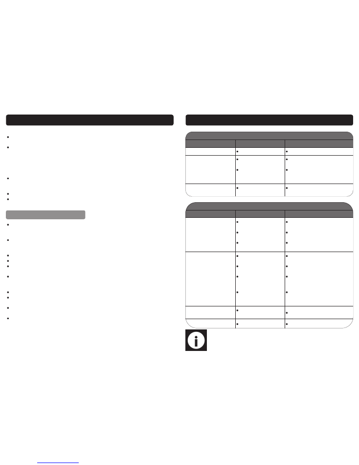
TROUBLESHOOTING
Note:
If none of the above solutions work then contact your local distributor
for repair, or contact SIP technical for more advise.
ARC
Symptom
Possible Cause
Solution
Alarm light on.
Overheated.
Allow the to cool .
Difficult to strike an arc.
Damp electrode.
Incorrect electrode.
Warm the electrode or re-
place.
Select the correct size elec-
trode to match the amperage
set on the machine.
Burns through thin metal.
Material too thin for
arc welding.
Use the TIG function.
TIG
Symptom
Possible Cause
Solution
Quality of weld is poor.
No gas flow.
Incorrect ceramic
nozzle.
Check condition of
tungsten.
Check gas flow and adjust as
required.
Select correct ceramic nozzle
to match tungsten.
Re-grind to shape or replace.
Overheating.
Fan problem.
Rear casing blocked,
obstructing air flow.
Poor connection on
earth clamp/
electrode holder.
Tungsten does not
match collet/collet
body.
Check fan connections, re-
place fan.
Check and clean.
Check and clean all connec-
tions.
Change collet/collet body to
match tungsten.
Difficult to strike an arc.
Tungsten in poor
condition
Re-grind to shape or replace.
Alarm light on.
Overheated.
Allow the to cool.

20
MAINTENANCE
Clear dust from the machine at regular intervals, if used in a dirty environment
the machine should be cleaned once a month.
Check all connections are clean and tight, if there is any oxidization clean the
connection with a mild abrasive or wire brush.
Check all cables for damage or degradation to the insulation, replace if any is
found.
Check electrode holder and earth clamps condition; Ensure they clamp tightly,
replace if damaged or loose.
If the machine is not to be used for a long time, store it in the original packing
and in a dry place.
9
SAFETY INSTRUCTIONS….cont
Ventilation must be adequate to remove the smoke and fumes during welding
(see the relevant safety standard for acceptable levels).
Toxic gases may be given off when welding, especially if zinc or cadmium
coated materials are involved, welding should be carried out in a well ventilat-
ed area and the operator should always be alert to fume build-up.
Areas with little or no ventilation should always use a fume extractor.
Vapours of chlorinated solvents can form the toxic gas phosgene when ex-
posed to U.V radiation from an electric arc. All solvents, degreasers and poten-
tial sources of these vapours must be removed from the arc area.
Severe discomfort, illness or death can result from fumes, vapours, heat, oxygen
enrichment or depletion that welding (or cutting) may produce. This will be pre-
vented by adequate ventilation or using a fume extractor.
Never
ventilate with
oxygen.
Lead, cadmium, zinc, mercury, beryllium bearing and similar materials when
welded may produce harmful concentrations of toxic fumes. Adequate ventila-
tion must be provided for every person in the area. The operator should also
wear an air supplied respirator, for beryllium both must be used.
Metals coated with or containing materials that emit toxic fumes should not be
heated unless coating is removed from the work surface. The area should be
well ventilated or the operator should wear an air supplied respirator.
Work in a confined space only while it is being ventilated and if necessary whilst
wearing an air supplied respirator.
Gas leaks in a confined space should be avoided, leaking gas in large quanti-
ties can change oxygen concentration dangerously.
Do not
bring gas cylinders
into a confined space.
Leaving a confined space you must shut off the gas supply at the source to
prevent possible accumulation of gases in the space if down stream valves are
left open. Check to be sure that the space is safe before re entering it.
Vapours from chlorinated solvents can be decomposed by the heat of the arc
(or flame) to form phosgene a highly toxic gas and other lung and eye-irritating
products. The ultra violet (radiant) energy of the arc can also decompose tri-
chloroethylene and perchlorethylene vapours to form phosgene.
Do not weld
or cut where solvent vapours can be drawn into the welding atmosphere, or
where the radiant energy can penetrate to atmospheres containing even mi-
nute amounts of trichloroethylene or perchlorethylene.
VENTILATION
10
SAFETY INSTRUCTIONS….cont
Some metals and metal composites have the potential to be highly
toxic; always wear a face mask .
When using the Inverter welder always ensure the operator as well as
those in the area use a welding mask with the correct shade filter
lens.
Caution:
The warnings and cautions mentioned in this user manual can not
cover all possible conditions and situations that may occur. It must be under-
stood by the operator that common sense and caution are factors which can-
not be built into this product, but must be applied.
19
OPERATING INSTRUCTIONS….cont
Clean the area to be welded, and the earthing point of all rust, paint and con-
taminants etc.
Connect the earth clamp dinse plug into the positive dinse socket on the weld-
er.
Place the earth clamp onto a cleaned area of the workpiece.
Fit the grounded tungsten into the TIG torch head.
Connect the TIG torch (not supplied) power connector to the negative dinse
socket on the welder.
Connect the regulator (not supplied) onto the gas bottle.
Connect the TIG torch gas pipe onto the regulator.
Check the TIG torch gas valve is closed.
Turn the regulator on.
Connect the welder to the electrical supply and switch on.
Caution:
Ensure all protective equipment is worn and bystanders are not in
the vicinity.
Set the amperage control to match the tungsten size.
Open the TIG torch gas valve.
Place a face mask over your face (not supplied).
Scratch the tungsten on the workpiece, when the arc is created proceed stead-
ily in one direction, maintaining a constant distance between the tip of the
tungsten and the workpiece.
Once all work has been done, switch the machine off and turn the gas off.
Note:
This is a DC welder and therefore can not be used for aluminium
welding.
PREPARATION FOR WELDING
WELDING

18
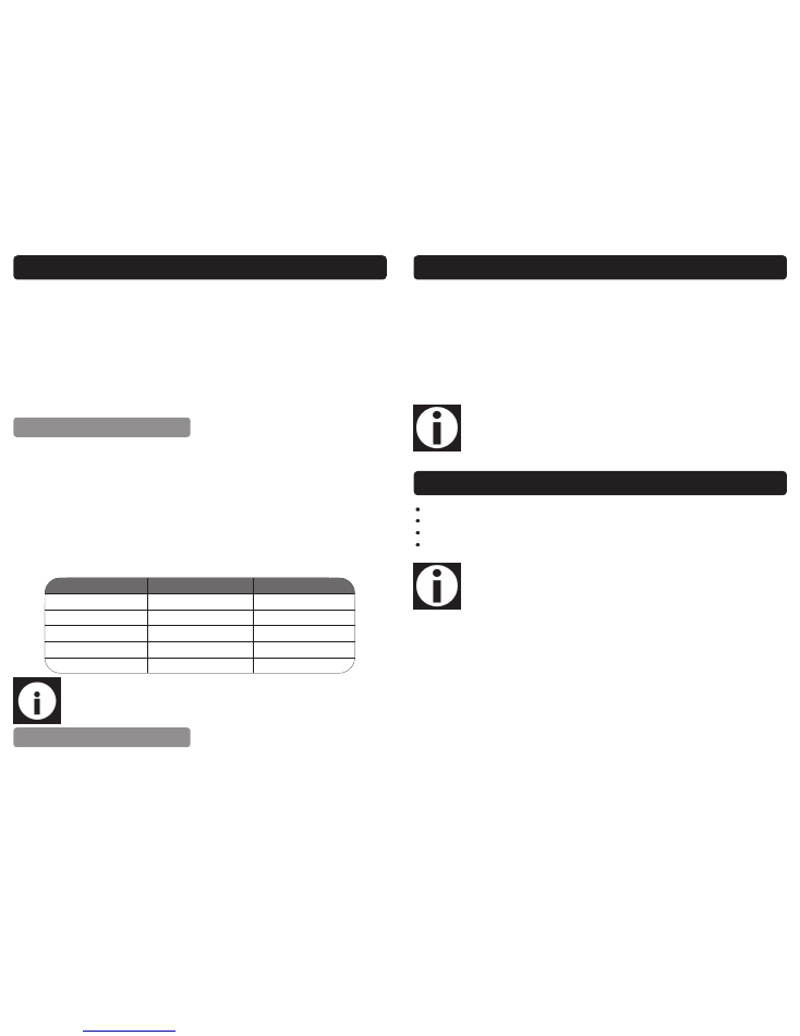
OPERATING INSTRUCTIONS….cont
The required tungsten diameter is determined by the thickness of the material to be
welded, for each tungsten size there are strict current limits which should be adhered
to. Too great a current causes excessive tungsten consumption and weld pool con-
tamination, whilst a too small a current causes arc instability.
The table below gives a guide as to which tungsten is most suitable according to the
material thickness. This table is only a guide, and values given are a indication only.
These welding current values are for thorium 2% (red) tungsten electrodes.
Welding
Thickness mm
Tungsten
Diameter mm
Welding Current
Steel
Welding Current
Stainless Steel
0.5
1.0
30-60
15-30
1.0
1.6
50-70
50-70
1.5
1.6
90-110
60-90
2.0
1.6
100-130
80-100
3.0
2.4
120-140
100-130
4.0
2.4
150-190
130-170
It is important to choose a tungsten with the correct diame-
ter for the current to be used. The tungsten will normally pro-
trude from the ceramic nozzle by 2 or 3mm, in order to
gain access to areas such as internal corners the tungsten
can be made to protrude by up to 8mm. The tungsten
should be sharpened facing the grinding wheel (see right
picture). The tip should be perfectly concentric in order to
avoid arc deviations. It is best to regularly inspect the tung-
sten to maintain peak condition.
Note:
The above is a guide only; always try a short weld test at the setting
selected. It is normal to make minor adjustments to achieve the required
weld.
PREPARING THE TUNGSTEN
11
ELECTRICAL CONNECTION
Warning!
It is the responsibility of the owner and the operator to read, understand and
comply with the following:
You must check all electrical products, before use, to ensure that they are safe.
You must inspect power cables, plugs, sockets and any other connectors for wear or
damage.
You must ensure that the risk of electric shock is minimised by the installation of appro-
priate safety devices; A residual current circuit Breaker (RCCB) should be incorporated
in the main distribution board. We also recommend that a residual current device
(RCD) is used. It is particularly important to use an RCD with portable products that are
plugged into a supply which is not protected by an RCCB. If in any doubt consult a
qualified electrician.
Connecting to the power supply 05703 & 05705:
These SIP Inverter welders (05703 & 05705) are fitted with a standard 230v ~ 13 amp
type plug. Before using the Inverter welder, inspect the mains lead and plug to ensure
that neither are damaged. If any damage is visible have the welder inspected / re-
paired by a suitably qualified person. If it is necessary to replace the plug a heavy
duty impact resistant plug would be preferable.
The wires for the plug are coloured in the following way:
Yellow / green
Earth
Blue
Neutral
Brown
Live
As the colours of the wires may not correspond with the markings in your plug, pro-
ceed as follows: The wire which is coloured blue, must be connected to the terminal
marked with N or coloured black. The wire which is coloured brown, must be connect-
ed to the terminal, which is marked L or coloured red. The wire which is coloured yel-
low / green should be connected to the terminal which is coloured the same or
marked
Always secure the wires in the plug terminal carefully and tightly. Secure the cable in
the cord grip carefully.

12
Connecting to the power supply 05707:
The 05707 is supplied without a plug fitted, it must not be connected to a standard
13A supply, consult the technical specification table (page14) for the required rating,
if in doubt contact a qualified electrician.
ELECTRICAL CONNECTION….cont
Note:
If an extension lead is necessary in order to reach the mains supply; The
cross section should be checked so that it is of sufficient size so as to reduce the
chances of voltage drops. Always fully unwind the lead during use.
Warning:
Never connect live or neutral wires to the earth terminal of the plug.
Only fit an approved plug with the correct rated fuse. If in doubt consult a
qualified electrician.
Note:
Always make sure the mains supply is of the correct voltage and the
correct fuse protection is used. In the event of replacing the fuse always
replace the fuse with the same value as the original.
Note:
Due to the input current required to run the inverter welder, it is advisa-
ble not to use an extension lead. No more than 1 welder should be ran
from the same ring main for the same reason.
17
OPERATING INSTRUCTIONS….cont
Fit the required electrode securely into the electrode holder.
Switch the welder on.
Set the amperage control to match your electrode size.
Place a face mask over your face (not supplied).
Bring the electrode into contact with the workpiece using a light tapping action
and withdrawing to create a gap of 1.5 mm – 3.0 mm.
Note:
Be aware that the electrode is now live, simply touching any part of
the workpiece will create a spark.
When the arc is created, proceed steadily in one direction keeping the gap
between the electrode and the workpiece constant.
When the weld is complete simply remove the electrode from the workpiece.
Remove any excess weld / slag with a wire brush / hammer (not supplied).
Clean the area to be welded, and the earthing point of all rust, paint and con-
taminants etc.
Place the earth clamp on to a cleaned area of the workpiece.
Connect the welder to the electrical supply but do not switch on.
Caution:
Ensure all protective equipment is worn and bystanders are not in
the vicinity.
You will need to purchase the following items in order to TIG weld (not supplied):
TIG torch (with gas valve) - SIP Part No. 05029 Regulator
Tungsten electrode
Bottle of argon gas
Filler rod
PREPARATION FOR WELDING
WELDING
TIG WELDING
The amperage control is operated by rotating the knob on the front of the welder;
Rotate the knob clockwise to increase the amperage and anticlockwise to reduce
the amperage. Once the amperage control is set do a short weld and check for cor-
16
OPERATING INSTRUCTIONS
There are no hard and fast rules by which a particular gauge of electrode is selected,
usually this is determined by the type of welding required and the thickness of the
workpiece e.g. a butt weld in 1.5mm (1/16”) sheet metal can be done by a 1.6mm or
2.0mm electrode, the difference being that the 2.0mm electrode will do the job
more quickly.
The table below gives a guide as to which electrode is most suitable according to the
material thickness. This table is only a guide, and values given are a indication only.
These welding current values are for the E6013 electrodes, for other types of electrode
consult their data sheet.
Note:
The above is a guide only; always try a short weld test at the setting
selected. It is normal to make minor adjustments to achieve the required
weld.
The welder should be set to a specific amperage to match the electrode size (see
above table).
ARC WELDING
AMPERAGE CONTROL
Electrode Size mm
Material Thickness mm
Welding Current (A)
1.6
1 - 1.6
25 - 40
2.0
1.6 - 2.6
40 - 70
2.5
2.6 - 4.0
60 - 100
3.25
3.0 - 5.0
80 - 130
4.0
5.0 - 7.0
130 - 170
Important information:
These units can be set to deliver different output currents at a
duty cycle that is written as a percentage on page 14. This percentage represents the
welding time in a 10 minute cycle, e.g. 60% means that the welding time is 6 minutes
and the rest time is 4 minutes. If a unit is used beyond its duty cycle the temperatures
of some components might become too high due to over use; The internal thermal
protector will then prevent the unit from operating. Its Intervention is Indicated by the
alarm light on the front panel, If this happens leave the machine switched on with the
fan running and allow It to cool down. The thermal protector will re-set automatically
after a short period of time when the components have cooled you will be able to
restart welding.
13
These SIP Inverter welders are covered by a 12 month parts and labour warranty cov-
ering failure due to manufacturers defects. This does not cover failure due to misuse or
operating the inverter welder outside the scope of this manual - any claims deemed
to be outside the scope of the warranty may be subject to charges Including, but not
limited to parts, labour and carriage costs, failure to regularly clean your inverter weld-
er will shorten its working life and reduce performance.
The warranty does not cover consumable items such as electrode holders & clamps,
etc.
GUARANTEE
Note:
Proof of purchase will be required before any warranty can be hon-
oured.
CONTENTS AND ACCESSORIES
Note:
If any of the above are missing or damaged, contact your distributor
immediately.
Inverter Welder.
Instruction Manual.
2m Welding Cable with Electrode Holder.
2m Earth Cable with Earth Clamp.
14
TECHNICAL SPECIFICATION
Note:
Only the T800 and T1400 should be operated from a 13A supply.
Note:
Operation of the T1600 from a 13A supply could invalidate the war-
ranty and affect performance.
Model
05703 T800
05705 T1400
05707 T1600
Input Voltage
230V ~ 50/60Hz
230V ~ 50/60Hz
230V ~ 50/60Hz
Input Current
13 amps
13 amps
16 amps
OCV
68V
68V
68V
Welding Current Range
(Amps)
10 - 80
20 - 140
20 - 160
Welding Voltage
20.4v - 23.2V
20.8v - 25.6V
20.8v - 26.4V
Weld Thickness (mild steel)
1.5mm - 4mm
1.5mm - 7mm
1.5mm - 8mm
Duty Cycle
80 amps @ 60%
140 amps @ 20%
160 amps @ 20%
81 amps @ 60%
92 amps @ 60%
62 amps @ 100%
63 amps @ 100%
71 amps @ 100%
Power Factor
0.65
0.65
0.65
Efficiency
85%
85%
85%
Insulation Class
H
H
H
Protection
IP21S
IP21S
IP21S
Net Weight
2.8Kg
3.8Kg
3.8Kg
15
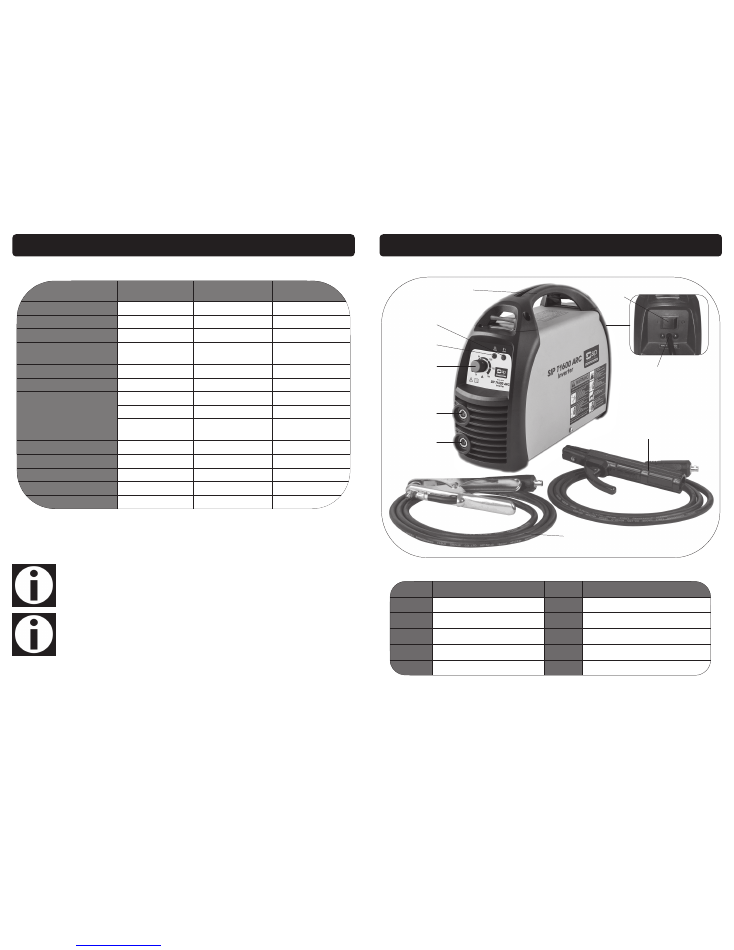
GETTING TO KNOW YOUR INVERTER WELDER
Ref. No. Description
Ref. No. Description
1.
Negative Dinse Socket
6.
Carry Handle
2.
Positive Dinse Socket
7.
On/Off Switch
3.
Amperage control
8.
Mains Lead
4.
Power Indicator
9.
Welding Cable
(c/w electrode holder)
5.
Thermal Overload Indicator
10.
Earth Cable
(c/w earth clamp)
1
2
3
4
5
6
7
8
9
10