Full Text Searchable PDF User Manual
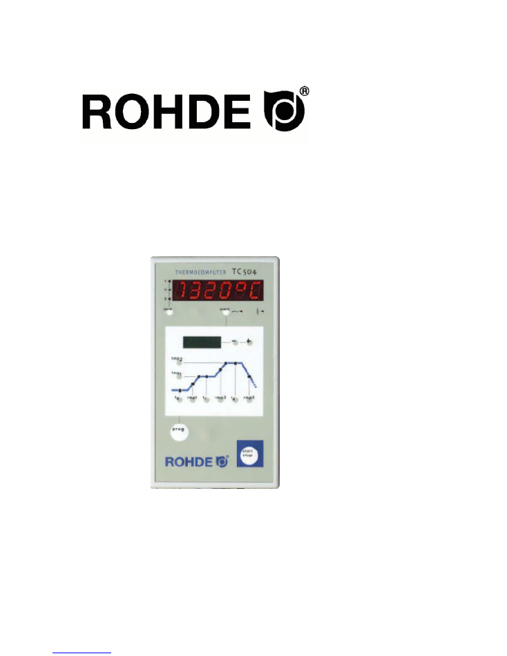
TC 504
In
st
ru
ct
io
n
M
an
ua
l

Ceramics: 06/2004
2
Table of Contents
Table of Contents......................................................................
Brief instruction...........................................................................
Operating elements.....................................................................
Firing curve.................................................................................
Calling up a Programme.............................................................
Initiating the firing process..........................................................
Display during firing....................................................................
Input and control of firing curve..............................................
SKIP value..................................................................................
Storing a Programme................................................................
Display of kiln temperature......................................................
Heating performance, control outlet status, time.........................
Locking the controller..............................................................
Power failure...............................................................................
Actual duration of a ramp............................................................
Kiln cannot follow ramp...............................................................
Forward switching in SKIP ramps...............................................
Programme abortion at failure.....................................................
Stopping the firing process..........................................................
Appendix A: Event display of TC 504......................................
Appendix B: Data and event memory.....................................
Calling up stored data.................................................................
Calling up stored events.............................................................
Appendix C: Configuration......................................................
Explanation of parameters..........................................................
Calling up configuration..............................................................
Appendix D: Data interface (optional).....................................
Appendix E: Calling up equipment..........................................
Appendix F: Electrical connection..........................................
2
3
3
4
5
5
6
7
7
8
8
9
10
10
10
10
11
11
11
12
15
16
17
18
19
21
22
22
23
General Information
You have opted for a TC 504 controller, the professional model
of the highly advanced bentrup TC 500 series. This controller
series applies world-wide leading state-of-the-art technology
for this controller type. The controller is very easy to operate
from the outside. Inside, however, it houses a multi-channel
controller structure, which can be freely adjusted to every
desired setting (see Appendix C). These operating instructions
will help you to become familiar with all the important features
of your TC 504. Please read it carefully including the safety
instructions of the manufacturer. Please make sure that the
controller is installed in an adequate distance from the kiln. It
should not be exposed to exhaust fumes or heat-radiation
emitted by the kiln.
Ceramics: 06/2004
3
Quick instructions
Starting the programme:
Changing the programme:
1.
Power on. Red display of actual
temperature. The power switch is located at
the bottom of the controller housing.
1.-2.
See left.
2.
Call up a programme by pressing the
button one or several times. The
programme number shows in the red
display, the corresponding final
temperature “tmp2” shows in the green
display.
3.
Call up adjustable firing curve values. The
values flash up in the green display.
3.
Starting or stopping the selected
programme.
4.
Changing the retrieved values shown in the
green display. New values are stored
automatically. t stands for time in hours, rmp
stands for ramp in °C/h and temp stands for
temperature in °C.
5.
Starting or stopping the selected programme.
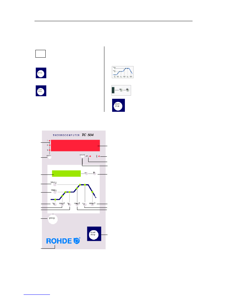
Operating elements
1 Display of current zone
2 Calling up another zone (only for kilns
equipped with multi-zones)
3 Display of nominal value
4 Calling up / input of final temperature
5 Calling up / input of 1
st
dwell time
6 Calling up / input of delay time
7 Calling up / input of 1
st
heating time
8 Calling up / input of 1
st
dwell time
9 Programme key
10 Keyboard lock in “O”
11 Display of actual value
12 Display of heating circuit status “On/Off”
13 Display of event status “On/Off”
14 Event switched on / off
15 Changing the retrieved values
16 Calling up / input of cooling time
17 Calling up / input of firing time
18 Calling up / input of heating speed to
final temperature
19 Starting and stopping a programme
1
2
3
6
5
4
7
8
9
10
19
12
14
16
17
18
11
15
1240°C.
1240
I
O
13
Ceramics: 06/2004
4
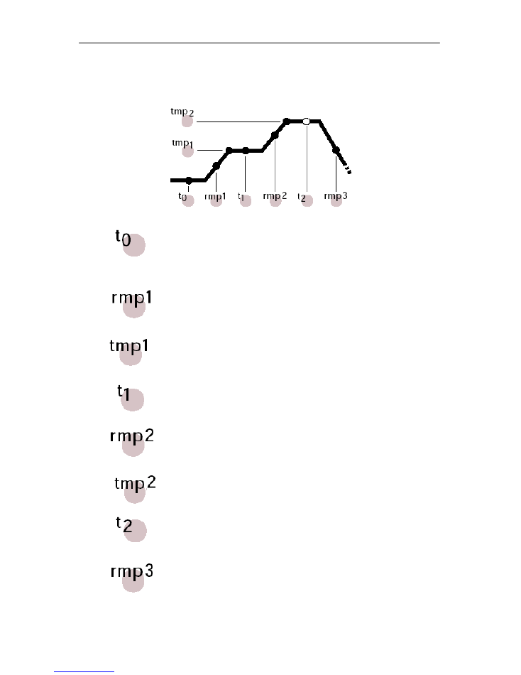
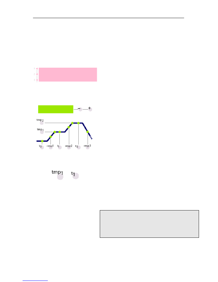
The microprocessor of your TC 504 controller allows you to control your kiln with high
precision and reproducible results. The firing curve of the TC 504 is illustrated in the following
diagram. In consists of various segments:
Delay time / delay of programme start
The controller waits for the preset period of time until it starts the
actual firing process. With this function the firing can be initiated
automatically, e.g. by night.
Heating to 1
st
dwell temperature
The kiln is heated up with the preset speed. The input is made in
degree Celsius per hour (for information on how to set the time,
please refer to Appendix C).
Temperature for 1
st
dwell temperature
The kiln is heated with the speed set above until it reaches the
1
st
dwell temperature. The input is made in degree Celsius.
Dwell time at 1
st
dwell temperature
After the kiln has reached the temperature, this temperature is
maintained for the preset period of time. The input is made in
hours/minutes.
Heating to final temperature
The kiln is heated up to the final temperature in the preset
speed. The input is made in degree Celsius per hour (for
information on how to set the time, please refer to Appendix C).
Temperature for 2
nd
dwell temperature
The kiln is heated with the speed set above until it reaches the
2
nd
dwell temperature. The input is made in Degree Celsius.
Dwell time at final temperature
The kiln maintains the final temperature for the preset time. The
dwell time ensures that the goods are heated thoroughly and
evenly.
Cooling down / end of programme:
After the dwell time is finished the kiln will cool down; this can
either happen controlled (e.g. 200° C/h) or uncontrolled (=SKIP).
The controller will terminate temperature control at 150° C and
indicates the end of the firing process by displaying “End” in the
green display (3).
Ceramics: 06/2004
5
Calling up a Programme
The TC 504 has the capacity of storing 10
firing curves (programmes). The
manufacturer has preset the programmes
with standard firing curves, which can be
modified. The preset programmes contain
the following values:
Prog.nr.
Description
t0(min) rmp.1(°C/h)
tmp.1(°C)
t1(min)
rmp2(°C/h)
tmp.2(°C)
t2(min)
rmp3
(°C/h)
01
drying 150°C
0
50
150
10
skip
150
10
skip
02
drying 200°C
0
50
200
10
skip
200
10
skip
03
glazing 750°C
0
150
750
10
skip
750
5
skip
04
bisquit firing 800°C
0
100
600
10
150
800
5
skip
05
slow bisquit firing 800°C
0
80
600
10
100
850
5
skip
06
bisquit firing 900°C
0
100
600
10
150
950
5
skip
07
earthenware 1050°C
0
150
300
5
skip
1050
20
skip
08
stoneware 1150°C
0
150
300
5
skip
1150
20
skip
09
pottery 1240°C
0
150
300
5
skip
1240
20
skip
10
pottery 1280°C
0
150
300
5
skip
1280
20
skip
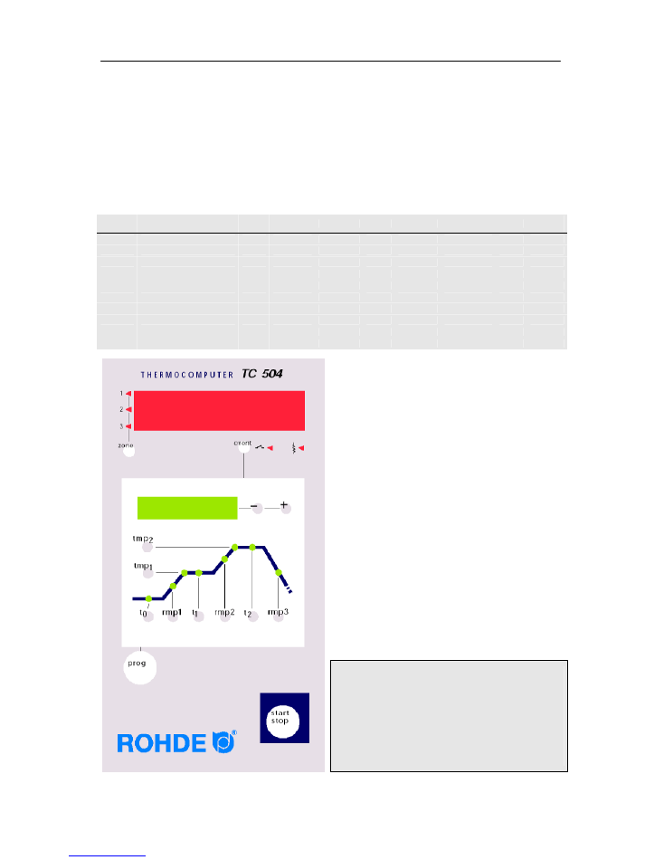
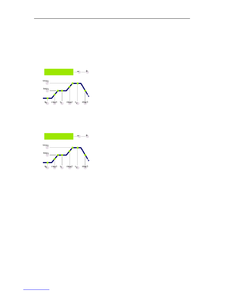
In the following example we will call up the
firing curve for programme number 04 and will
start the firing process.
After the TC 504 has been switched on the
red display will indicate the momentary
temperature.
You can call up programme number 04 by
pressing the Prog key four times. In the green
display you will see the respective final
temperatures of the selected programmes.
Initiating the firing
process
In order to start the programme, press the
Start key. In the firing curve the green LED for
the current firing segment will light up now.
The green display shows the current nominal
temperature. The red display shows the
current kiln temperature.
Please note:
The flashing decimal dot on the right side of
the red display shows that a firing process is
in operation.
Programme values are indicated by a
flashing
light in the respective firing segment in the green
display
P 4
800
Ceramics: 06/2004
6
Display during the
firing process
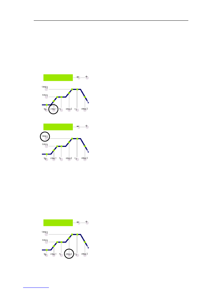
Usually the green display shows you the current
nominal temperature during the firing process. While
the kiln is heating up this temperature will “count”
upwards according to the programme settings. Every
15 seconds the maximal temperature of the firing
curve will flash up. This makes it easy for you to
check if you have inserted the correct value without
having to press any button.
By means of the firing curve you can monitor how the
TC 504 executes the firing segments one by one.
The programme is finished, when the kiln has
reached 150° C during the cooling process. At that
moment the display (3) will show “End” for the end of
the programme (see diagram to the left).
1240
End
Ceramics: 06/2004
7
Input and control of a
firing curve
You can view and adjust the preset values of the
firing curve at any time, i.e. even while the
programme is running. You only have to stop the
programme if you want to change the values.
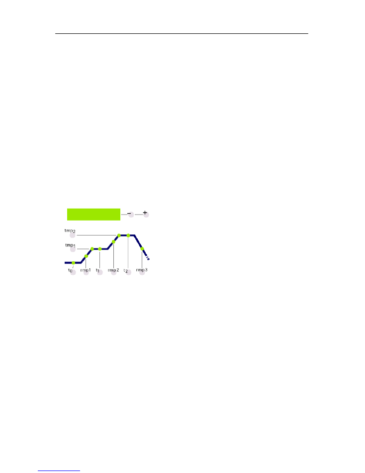
In order to control e.g. the heating speed, press the
rmp1 key. The currently programmed value for
heating appears in the green display in °C/h. The
corresponding section of the firing curve lights up.
If you want to change this value just insert a new
value using the +/- key.
In order to control e.g. the final temperature press the
tmp2 key. Again the current value will appear on the
green display the corresponding section on the firing
curve will light up.
The value can be changed as described above.
The SKIP value
All values can be controlled and changed in the way
described above. The order in which you control or
change the values is not relevant. The only thing you
have to keep in mind is that you have to stop the
programme if you want to change any values. If you
pause checking the values for more than 15 seconds
while the programme is running the display will return
to the active nominal value.
Most of the times it is desirable to reach the final
temperature during the 2nd heating phase as quick
as possible. For this purpose you can set the SKIP
value. Select the desired firing phase by pressing the
rmp2 key.
You can select the SKIP value by exceeding the
maximal value 998° C/h.
100
1240
SKIP

Ceramics: 06/2004
8
Storing of
programmes
The TC 504 automatically stores all changeable
values of the firing curve.
Display of kiln
temperature
The red display permanently shows the values of the
process. These are for example: current kiln
temperature, heating performance, status of control
outlets etc. You can retrieve the kiln temperature
values one by one by pressing the “zone” (2) key.
The TC 504 also supports multi-zone kilns. The
symbols to the left of the red display indicate which
zone belongs to which kiln value. The sequence of
the displayed process values can be determined in
the configuration. By pressing the key “O” (10)
followed by the key “zone” (2) the following values
will appear on the display (11).
Current kiln temperature
Display of current actual value. For multi-zone kilns
the actual values can be retrieved by pressing the
“zone”
key (2) several times (for zone number see
symbol to the left).
„over“
: No sensor connected, sensor broken, sensor connection
broken or temperature range exceeded.
„under“
: Sensor / supply line connected incorrectly. When you
reverse the polarity please make sure that you connect according
to the colour coding. If you connect incorrectly on both sides (!)
the controller cannot detect this and will overheat the kiln.
„invalid“:
Value measurement invalid, measured value of sensor
invalid or failure of measurement device.
Current kiln heating performance percentage.
For switching kilns the percentage of the heating
performance is displayed as the relation
impulse/break (e.g. 50% = kiln 15 s on and 15 s off).
„channel off“
: No controller routine active, e.g. during delay time
or when the programme has not been started.
„channel over“
: Controller channel switched off, due to
exceeded temperatures (e.g. due to “over” error at measurement
input.
„channel gradient error“:
For safety reasons the controller
checks the minimal temperature increase during full load. If the
temperature increase drops under 3°C per 15 min the firing will
be aborted showing this error message. Typical reasons for this
error: The heating spiral is too old or broken, a phase of the
mains supply or the power relay has failed, short circuit of
sensor. No controller failure!
1240°C.
ovEr
undEr
inval
27 P
ch. ovr
ch. off
ch. Grd

Ceramics: 06/2004
9
Switch status of the control outlets
The number of the outlets activated is displayed
(the example shows all four outlets are activated).
The function of the outlets is determined during
configuration.
Information on special process events
Any special process events are displayed here. To
the left “E” is displayed permanently, to the right a
code (here “A4”) appears if required. The possible
events and codes will be explained in Appendix A.
Power consumption since programme start
The TC 504 calculates the power consumption of
the current firing by consulting the operating cycles.
The prerequisite for this is that the correct kiln
performance has been entered once during
configuration (see Appendix C).
Operating time of the heating elements since
programme start
The TC 504 calculates the net operating time (i.e.
only the actual operating time) for the current firing
since programme start by consulting the operating
cycles. In this way the load on the kiln can be
determined during and after the firing.
Overall operating time of heating elements
As above, the individual results are added up to an
overall value. This makes it easy to assess the
service life of the heating elements. For safety
reasons the meter can only be reset by the
manufacturer.
Current day and time
The TC 504 can be equipped with a real-time clock
with weekday function for an automatic programme
start (optional, can be upgraded). If the TC 504 is
equipped with this function the weekday and time
are displayed in this place for control purposes.
O
1240
0.24
E
A4
0.07
1.05
Fr.
14.45

Ceramics: 06/2004
10
Locking of controller
The TC 504 can be locked against unauthorized
access by a key lock.
Press the
“O”
of ROHDE for at least 3 seconds. If
the keys are locked you can see a dot in the red
display on the left side next to the temperature
display.
In order to unlock the keys press the “O” in ROHDE
again, until the red dot disappears.
Power failure
Should a power failure occur during firing the firing
will be halted. When the power returns the TC 504
will continue firing at the stage of the programme
where the power failure occurred. If the kiln
temperature has dropped by more than 50° C during
firing, the firing will be interrupted (an error message
will appear, see Appendix A).
If the power failure lasts longer than 30 minutes the
programme will be aborted, as the quality of the
goods cannot be safeguarded any more.
Actual duration of a
ramp
Ideally the duration of a ramp will be exactly as long
as programmed. However, if the current temperature
at the beginning of the firing is already higher than
the first value, then the time will be recalculated.
Example: Ramp in 2 hours to 500° C. The kiln
already has a temperature of 250° C, thus the
remaining time will be only 1 hour. The ramp will be
terminated exactly when the time is up.
Kiln cannot follow
ramp
What happens if the kiln cannot perform the required
temperature increase? Example: In 1 hour to 1000°
C. The TC 504 will perform as follows (only if
parameter number 9 is set to 0 or 1): As soon as the
controller has regulated the kiln at 100% heating
performance and thus no further regulation can take
place, the ramp time (and thus the nominal
temperature) will be held (display (3) flashes “hold”).
If the kiln temperature has caught up the timer will
continue to run. In order to prevent the oven from
getting stuck in a ramp due to insufficient
performance the controller has been set to
automatically switch to the next level. Outgoing from
the “hold” function you can also terminate the halt
manually (“
O
” in ROHDE followed by “
prog
” key),
see below in section “Interrupt process”.
Ceramics: 06/2004
11
Forward switching
for SKIP ramps
In the case of uncontrolled heating or cooling ramps
the TC 504 will only switch to the next segment when
the final temperature has been reached. For multi-
zone kilns the TC 504 will wait at every zone. In order
to prevent the kiln from locking itself due to heat
shifts between the zones a complex algorithm
automatically decides when a segment has to be
terminated.
Programme abortion
at failure
In the case of severe failure (e.g. broken sensor) the
TC 504 will interrupt the firing process.
Stop firing process
The TC 504 allows you to stop the firing process
manually. By pressing the “
O
” key in ROHDE
followed by the “
prog
” key the controller will stop the
firing process (the green display flashes “hold”). This
means that the time and the nominal temperature of
a ramp will be stopped. The kiln will be held at the
current nominal temperature for an indefinite period
of time (not the case for uncontrolled ramps!). The
firing process will only be continued if you press the
“O
” key in ROHDE followed by the “
prog
” key again.
hold

Ceramics: 06/2004
12
Appendix A:
Event display of
TC 504
Special events (power failure, sensor break, kiln
problems etc.) will be detected by the controller and
will be treated accordingly. Important events will be
displayed immediately on the red display according
to the codes (see example to the left, code A4). The
events are stored internally (see Appendix B).
The event codes are categorized into operating and
controller problems (code A…), power failure
problems (code B…), internal problems (code C…)
and hardware problems (code D…)
The possible event messages and their meanings
are listed and explained below.
Event A1
Error at measurement input
Controller switched off due to error at measurement
input (e.g. exceeding of measure range). The error
will be reset after restarting the programme.
Possible causes:
• Thermocouple or supply interrupted
• Maximal temperature of controller exceeded
• Thermocouple connected to wrong poles
(Temperature display „under“)
Event A3
Safety circuit activated
If the maximla programme temperature has been
exceeded by more than 20°C the safety circuit gets
activated and the safety power relay switches the
kiln off (only if installed and configurated). This
prevents the kiln from overheating.
Possible causes for overheating:
• Kiln power relay stuck in „ON“ position
• Contact of kiln power relay closed permanently
E
A4

Ceramics: 06/2004
13
Event
A4
Temperature increase too low despite heating on
full load
This error message
always indicates a problem at
the kiln
. Possible causes:
• Mains supply fuse / phase, heating element defect
• Heating elements too old (at high temperatures)
• Thermocouple or supply short-circuit
• Power relay defect (often occurs during firing)
Event A5
Kiln does not follow the programmed increase
In contrast to Event A4 here the cause can also be
that the programmed temperature increase has been
chosen too high for the kiln to follow. This message
will only be activated if it has been set during
configuration.
Event A8
Increase contiued automatically
If the kiln cannot follow the temperature increase the
ramp is halted (see section on „kiln cannot follow
ramp“). If the controller contiues the programme after
the halt period has passed
without success
this
message will be displayed for 1 minute.
Event A9
SKIP ramp forcefully terminated
If the controller has tried unsuccessfully to heat the
kiln to final temperature in an uncontrolled ramp the
controller switches to the next segment
(see section „uncontrolled ramps (SKIP)“). For the
information of the operator this message will be
displayed for 1 minute.
Event B2
Firing is continued after power failure
After the power has returned after failure the firing
process has been continued successfully.

Ceramics: 06/2004
14
Event B3
Firing has been interrupted after power failure
After the power has retured after power failure the
firing process has been aborted as e.g. the kiln
temperature has dropped too far in the meantime.
Further information about the event might be
displayed by adding a decimal number (e.g.
B3.4
=
temperature has dropped too far). If this message
appears immediately after you switched on the
controller you can
ignore
it. In this case it only
signifies that the controller had been switched off at
the last firing while the programme was still running.
Just start with the programme input.
Event C1, C2
C3, C4
Internal problem
Technical support necessary (C1 memory for
measured value defect, C2 measured value
unprecise, C3 communication error of system bus,
C4 wrong configuration of system bus).
Event D1, D2
D3, D4, D5
Hardware failure
Technical support necessary (D1 processor failure,
D2 RAM defect, D3 bus failure, D4 configuration bus
defect, D5 Calibration invalid).

Ceramics: 06/2004
15
Appendix B
Data and events
memory
Your TC 504 controller is equipped with a memory for
data and events. All data produced during the entire
firing process are recorded. This is a unique feature
in controllers of this kind. You will no longer have to
waste your time with monitoring the firing process
when problems occur (and then nevertheless miss
the crucial moment)!
Data memory
The data memory records all important values once
per minute (kiln temperature, switching, timing etc.).
This enables you to view the last 36 hours of the
firing process. The data is background-safed
automatically as long as the controller is switched on
(no matter if the firing process is activated or not).
When you switch off the controller the data will be
deleted.
Event memory
The event memory will only record values if special
events have occurred. These can be e.g. programme
interruption due too kiln problems, power failure,
interference by the operator etc. You can always call
up the last 50 events. In the case your kiln requires
servicing this will help the controller manufacturer to
find and solve the problem quickly and successfully.
Both the data and the event memories contain
basically the same information, namely the current
kiln temperature and kiln performance (for multi-zone
kilns of all zones), the nominal temperature, the
remaining time, the programme segment, the status
of the control outlets and the process information.
If the controller is equipped with a real-time clock the
date and time will be stored additionally. This makes
a fast and continuous reconstruction of all events
possible.
Ceramics: 06/2004
16
Calling up stored data
In order to call up the stored data please procede as follows:
Press the
“O”
key followed by the
tmp1
key. You may do
this at any time, even if a programme is in operation.
The red display will show the letter “L” (for “Log”) and a
consecutive number. The other displays work as during
normal operation (i.e. nominal value display, segment
display, etc.). Likewise you can call up the process values
by pressing the “
zone
” key (2).
In order to make this mode of the display distinguishable
from the “normal” display the red decimal dot does not flash
when a programme is in operation.
Now you can call up the following values which have been
recorded in one-minute steps by using the keys
rmp1
and
t1.
You can call up the stored data value by value (skip to
next with
rmp1
and to previous with
t1
).
If you do not press any key for 15 seconds the data memory
will be switched off automatically and the current values will
be displayed again. Alternatively you can also leave the data
display by pressing the
“O“
in
ROHDE(10) key followed
by
“tmp1“
(5).
Please note:
The controller stores a value every 60 seconds. A
very short switch impulse might not be visible in the data
memory if it has happened
in between
two recordings.
L
1
21

Ceramics: 06/2004
17
Calling up stored
events
In order to call up the event memory press the “
O
” key
followed by the
tmp2
key.
You may do this at any time, even if a programme is in
operation.
The red display will show the letter “E” (for “Event”) and
a consecutive number. You can call up the last 50
events.
Please note:
The event that has occurred last (i.e. the latest
event) has the lowest number and will be displayed as first.
The way in which the values are displayed is absolutely
identical to the one described in the section on calling up
stored data.
The event memory records events continuously. The
memory can only be cleared by the manufacturer, as it is
an irreplaceable means of detecting failure.
If the event or data memories are empty the display
shows “- -“ (see left).
E
2
E - -

Ceramics: 06/2004
18
Appendix C
Configuration
Some of the settings of the TC 504 depend on the kiln or
the application. Usually the required settings have been
made by your kiln manufacturer. If you are technically
minded you may make changes yourself if required. The
controller will store changes permanently. The following
table shows an overview of the parameters.
Par.Nr.
Description
Preset
Unit
01
Kiln performance
0,0
KWh
02
< reserved >
0
-
03
Thermocouple Code (S,R,K,J)
-
04
Maximal temperature of kiln
1320
°C
05
Proportional range
2.0
%
06
Reset time
200
S
07
Delay time
10
S
08
Cycle time
30
S
09
Behaviour at heating problems
1
-
10
Number of heating segments
1
-
11
Input of ramp as gradient or time
grad
(grad/time)
12
Funktion of 1. additional control outlet
1
-
13
Funktion of 2. additional control outlet
0
-
14
Funktion of 3. additional control outlet
0
-
Attention!
If you apply the wrong settings you can easily cause
damage to the kiln and goods. It is your own responsibility
to assess the results of changes of parameters, or
whether it is better not to apply any changes at at.
Certain settings are blocked against changing for safety
reasons (e.g. the changing of thermocouple type S/R to J/K or
vice versa).

Ceramics: 06/2004
19
Explanation of parameters
(in brackets: parameter numbers)
Kiln performance (1)
The kiln performance value is only used for calculating the energy consumption. For multi-
zone kilns you have to input the overall performance. The controller assumes an even
distribution of heating performance for the calculation.
Thermocouple Code (3)
Type of the temperature sensor. S=PtRh10%-Pt, R=PtRh13%-Pt, K=NiCr-Ni, J=FeCu-Ni.
Change from S/R to J/K and vice versa locked for safety reasons.
Maximal temperature of Kiln (4)
Highest insertable temperature.
Please note that this upper temperature level should
NEVER lie above the maximal kiln temperature!
Proportional range (5), reset time (6), delay time (7)
According to these parameters you can adjust the controller to the characteristics of your
kiln. The auto-tuning mechanism for the standard parameters ensure excellent controller
function even without individual setting.
Cycle time (8)
Decides the switching frequency of the power relay. A cycle time that is too short will result in
increased wear of the power relay, if the cycle time is too long the kiln will be heated
unevenly. The preset value of 30 s has proved to be a good compromise.
What to do in case of heating problems (9)
If the setting is 0 the controller will take all delays during heating into account. The time will
be
held
(“hold”) in controlled ramps if
one
segment is heating on full load. This setting
ensures that all segments of a heating ramp are properly controlled as far as technically
possible. In multi-zone kilns this is possible even with low performance reserve. With this
setting the programmed heating time might be exceeded considerably, due to frequent “hold”
periods.
Setting 1 (standard) is the same as setting 0, with the only difference that the time will only
be held when
all
zones are heating on full load. Thus the kiln performance will be used fully
during heating with the compromise that the individual zones might not be controlled. For
single-zone kilns the settings 0 and 1 lead to the same result!

Ceramics: 06/2004
20
With setting 2 the controller only checks the temperature increase during full load. As long as
a certain temperature increase is being measured (3° C per 15 min.) the firing process will be
continued.
For setting 3 the controller does not control the heating process at all. You should only chose
this setting if it is
explicitly
desirable (e.g. when the kiln has to be opened during operation).
Otherwise the safety of operation cannot be safeguarded. With this setting the controller will
not detect irregularities, as e.g. a short-circuited thermocouple, and the kiln might overheat.
Number of heating zones (10)
The TC 504 is also available for 2 or 3 control zones. With these parameters the number of
actually used controlled zones can be adjusted. Several controlled zones require an
accordingly contructed kiln (several thermocouples, power relais and heating group). The
temperature distribution for real multi-zone control is exceptionally good.
Input of ramps as gradient or time (12)
The values for heating and cooling segments can be input either in degree Celsius per hour
(°C/h) or as time – you can choose the unit according to your preference.
Funktion of 1./2./3. additional control outlet (13) ff.
The TC 504 is available with up to 4 control outlets. For single-zone kilns you can opt for up
to 3 control outlets for special functions. The respective functions have to be configurated.
The settings have the following meanings:
0 – control outlet OFF (no function)
1 – outlet for safety power relay: ON during programme in operation, OFF for over
temperature
2 - EVENT: outlet can be programmed as ON or OFF for every semi-segment.
Up to 2 outlets can be configurated as EVENT. After configuration please press the keys
event1
or
event2
during programme setting and insert for every segment “0” (=off) or “1”
(=on). Every control outlet will be switched accordingly when the programme is running. In
this way you can for example contol the cooling flaps
3 - ON during programme
4 - ON during programs, but not during delay time
5 - ON at end of programme
(for further functions please contact us)
The parameters (12), (13) and (14) will only be displayed if your kiln is equipped with the
according modules and number of zones (i.e. according to the number of control outlets).

Ceramics: 06/2004
21
Calling up the
configuration
Please press the
zone
key and keep it pressed for
approx. 3 seconds. The TC 504 will switch into
configuration mode and shows the first parameter of
the list (see previous page). The red display shows
the parameter number, the green display shows the
current value.
By pressing the keys
tmp2
or
tmp1
you can
navigate through all parameters of the list and
change them by pressing the +/- keys.
In order to leave the configuration mode please
press and hold the
zone
key as before. If you made
changes and you want to store them permanently
please
keep
the
zone
key
pressed
until the
message “Save okay” is displayed. This will prevent
the parameters from being changed accidentially.
Extensive
parameter list
We kept the above mentioned parameter list as
simple and compact as possible. It will allow you to
adjust the parameters for most applications.
However, many functions of the TC 504 remain
“hidden”. The
extensive parameter list
contains
more than 2,000 parameters and allows for an
absolutely unrestricted configuration of the entire
controller layout. You can set different parameters
for the individual zones, servodrive control, analog
outlets and many more.
The extensive parameter list can be deblocked by
setting a jumper. This can be done either by using
the TC 504 keyboard or the configuration software
WinConfig in Microsoft Windows (only for TC 504
with interface – see Appendix D).
For further information please see the “Technical
Manual TC 500 Controller Series”. This manual
(PDF format), as well as WinConfig can be
downloaded free of charge at
http://www.bentrup.de
.
Sav.okY

Ceramics: 06/2004
22
Appendix D
Data interface
The TC 504 can be equipped with a RS232C data
interface (for connection to a PC serial port) or a
RS422/485 interface for industrial use. The electric
signals are separated by galvanization. With the
data interface you have full access to all process
values, programmes, configuration parameters and
operation commands. This allows for complete
remote control. The following examples are typical
applications:
• Changing of configuration with bentrup WinConfig
(free software)
• Design of personal programs, direct access to
controller via public protocol
• Design of personal programs, access to controller
via simple command (e.g. “START”) with Windows
DDE (bentrup FIELDBUS driver required)
• Visualisation for complete solutions, data
measurement and recording, administration of
programmes and configurations with bentrup
WinControl.
For a detailed description including protocols please
visit the manufacturer’s homepage at
http://www.bentrup.de.
Appendix E
Calling up of layout
If you press the
zone
key while your controller is
starting up, the TC 504 will display the hardware
version and the upgrades if there are any installed.
The codes have the following meaning from left to
right:
• Number of control channels *
• Number of contol outlets *
• Number of analog outlets *
• y/n: real-time clock installed: Yes / No
• y/n: Extended programme store: Yes / No
• Hardware version code
* The actual number can be lower, see number on
the type plate of the controller behind the
thermocouple code (e.g. TC 504-S-14- .. = 1 zone
/ 4 outlets)
34.2.Y.Y.1
Ceramics: 06/2004
23
Appendix F:
Electrical
connection
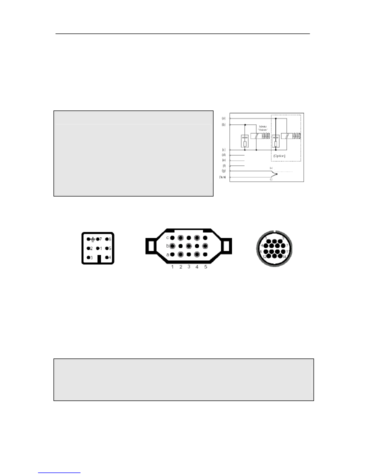
Simplified switch diagram of a kiln
Important Note:
The specifications given here are exemplary only. The
electrical connections are determined by the customer and
often deviate from the specifications given in this example.
Please check the documentation provided by the kiln
manufacturer. If the controller layout is suitable for more than
one zone or if it is equipped with more than two outlets,
please use the HAN15DX connection (see additional
description).
Plug designation
HAN7D a
HAN15D a
CPC14 a
Connection Function
HAN7D a
HAN15D a
CPC14a
a
Additional control outlet
7
C3
12
b
Control outlet connector (phase)
6
A3
14
c
Control outlet connector (zero)
1
B3
13
d
Ground wire *
termination fitting
11
e
Power supply phase
5
A1
8
f
Power supply zero
2
B1
9
g
Thermocouple +
3
B5
1
h
Thermocouple – (Pt Rh Pt)
4
C5
2
n
Thermocouple - (NiCrNi)
4
A5
3
* The ground wire
must
be connected!
Important Note:
Please compare the type of the thermocouple with the type specification that is stated on the back of
the controller. Otherwise you might cause damage to the kiln and the kiln content!
We reserve the right to make changes contributing to technical improvement.
Instruction Manual TC 504 V1.20 (C) 2004 HELMUT ROHDE GMBH DEUTSCHLAND
Ground wire
220 V phase
220 V zero
Thermocouple
a….n Connection f. control unit