Full Text Searchable PDF User Manual
NEA H 24 V & NEA H 230 V
REHAU ROOM THERMOSTAT
USER INSTRUCTIONS AND QUICK INSTALLATION GUIDE
www.rehau.co.uk
DE
EN
CZ
ES
FR
GR
HU
IT
NL
PL
RO
RS
RU
SE
TR
Safety
Important info
Your benefit
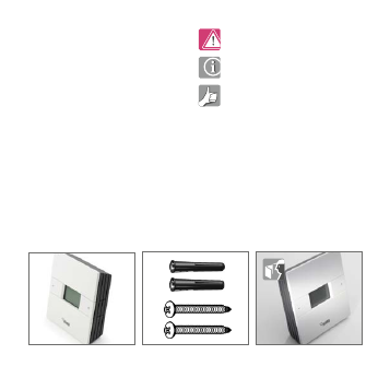
Scope of supply
Thermostat (1 pc)
Anchors & Screws (2 pcs)
Manual (1 pc)
Contents
Scope of supply . . . . . . . . . . . . 30
Introduction . . . . . . . . . . . . . . 31
Product compliance and safety . . . . 31
Safety information . . . . . . . . . . . 31
Installer parameter settings, expert level 32
Mounting position and installation . . . 33
Removing cover from the Nea . . . . . 39
Thermostat control and display . . . . 40
Adjusting set temperature . . . . . . . 42
Operational modes. . . . . . . . . . . 42
Display messages . . . . . . . . . . . 43
General function information . . . . . . 43
Technical data . . . . . . . . . . . . . 44
30
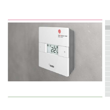
Introduction
Thank you for purchasing the REHAU room
thermostat Nea. The Nea H is a parameter-
izable digital room thermostat which is
available in 24 V and 230 V versions and
offers simple temperature adjustment of
your heating system.
By purchasing one of the REHAU room
thermostats Nea you have decided on an
electronic thermostat that allows you to
adjust surface heating applications
individually, such as underfloor, wall or
panel heating. Tailor-made single room
control can be implemented depending on
system design. A clear energy saving is
possible by reducing temperature.
We hope you enjoy this product.
Product compliance and safety
Product compliance
This product is CE compliant and meets the
following EC Directives
- Electro-Magnetic Compatibility Directive
2004/108/EC
- Low Voltage Directive 2006/95/EC
Safety information
Use in accordance with the
regulations.
The room thermostat Nea H is to be used
for the room control of hot water surface
systems inside the house and not
considered for flow control or flow control
supervision in case of heating or cooling. In
this context the Nea H must be used
exclusively to drive thermal actuators. The
manufacturer is not liable for improper use.
Authorized specialists
The electrical installation must be
performed according to the current national
regulations as well as according to the
31
DE
EN
CZ
ES
FR
GR
HU
IT
NL
PL
RO
RS
RU
SE
TR
regulations of your local electric power
utility company. These instructions require
special knowledge corresponding to an
officially acknowledged degree in one of the
following professions:
- Electrical Equipment Installer or
Electronics Engineer
According to international regulations, as
well as according to comparable profes-
sions within your specific country law.
Sources of danger
The thermostat must be discon-
nected from the mains supply or fuse
before
removing the cover.
Emergency
Switch off the voltage to the
complete individual room temperature
control system.
Installer parameter settings, expert level
The thermostat Nea is equipped with
various parameters. These parameters can
easily be modified for your specific
application. See the Nea Service and Expert
Parameters section at www.rehau.com/nea
Please note that the parameter
sections must only be entered by an
installer or competent person. Changing
these parameters can have a serious effect
on the heating system.
Please enter any parameter changes
in the installer notes section.
32
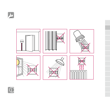
Mounting position and installation
To ensure trouble free operation and
efficient control. The room
thermostat Nea is best positioned in a draft
- free area and at 130 cm from the floor. Do
not position the thermostat near any heat
source, behind curtains, direct sunlight or in
an area of high humidity.
- Not to be positioned on exterior wall
For your benefit symbol
To ensure trouble free operation and efficient control. the room thermostat Nea
is best positioned behind a door and at 130cm from the floor.
(Pic)
Do not position the thermostat:
1. Near any heat source (pics)
2. Behind curtains(pic)
3. Direct Sunlight(pic)
4. In a bathroom or area of high humidity(pic)
Info symbol
· Not to be positioned on exterior wall
· Do not install the remote sensor (if applicable) in an empty tube
· Only the temperature at the position of remote sensor (if applicable) is measured
130cm
130cm
33
DE
EN
CZ
ES
FR
GR
HU
IT
NL
PL
RO
RS
RU
SE
TR
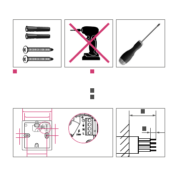
Installation
1
Wall mounting
For wall mounting, mark and mount the rear
case to the wall. The Nea is suitable for wall
boxes with a center hole distance of
60 mm.
* screw head maximum size
2
Wiring connections
Solid and
stranded wire
max 1.5 mm² square
A
55 mm
B
8 mm
7 mm*
60 mm
19 mm
75 mm
88 mm
A
B
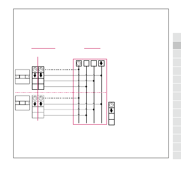
Wiring connection Nea H 24 V & 230 V
34
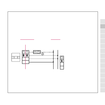
Nea H wiring
* Room thermostat Nea H 230 V and 24 V are separate models
Optional External Time Switch
Max. 5 Thermal Actuators
L/L1 N/L2
L1
L2
L
N
24 V
230 V
230 V AC
L N
24 V AC
L1 L2
230 V AC / 0.2 A
Resistive Load
24 V AC / 1 A
Resistive Load
24 V
230 V
H*
H*
H*
H*
L
N
External time switch (Phase balance)
Load (Thermal Actuators)
Neutral
Phase
35
DE
EN
CZ
ES
FR
GR
HU
IT
NL
PL
RO
RS
RU
SE
TR
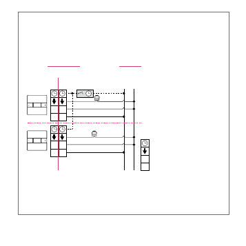
* Room thermostat Nea H 230 V and 24 V are separate models
Max. 5 Thermal Actuators
Max. 5 Thermal Actuators
Optional External Time Switch
L/L1 N/L2
L1
L2
L1
L2
L
N
L
N
230 V AC
L N
24 V AC
L1 L2
230 V AC / 0.2 A
Resistive Load
24 V AC / 1 A
Resistive Load
24 V
230 V
24 V
230 V
H*
H*
H*
H*
L
N
External time switch, phase balance
Load (Thermal Actuators)
Neutral
Phase
36
* Room thermostat Nea H 230 V and 24 V are separate models
L/L1 N/L2
L1
L2
L1
L2
L
N
L
N
230 V AC
L N
24 V AC
L1 L2
230 V AC / 0.2 A
Resistive Load
24 V AC / 1 A
Resistive Load
24 V
230 V
24 V
230 V
H*
H*
H*
H*
L
N
External time switch (Phase balance)
Load (Thermal Actuators)
Neutral
Phase
WIRING CENTRE
37
DE
EN
CZ
ES
FR
GR
HU
IT
NL
PL
RO
RS
RU
SE
TR
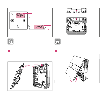
Ensure that the cable is contained
within the shaded area.
3
Locate the front cover on rear case,
ensuring that the hinged clips are located
first.
Ensure that the two arrows are
aligned properly before closing.
4
Locate hinge first
20 mm
25 mm
38
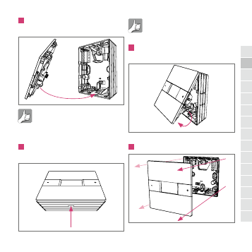
5
Gently locate the cover locking clip in
rear case location and close it.
Ensure cover locking clip is secure in
the rear case.
Removing cover from the Nea
1
Use tool to gently push the cover
locking clip vertically.
Recommended width 5 mm for tool.
2
Pull the base of the cover assembly
away from rear case.
3
Remove cover and put in safe place.
39
DE
EN
CZ
ES
FR
GR
HU
IT
NL
PL
RO
RS
RU
SE
TR
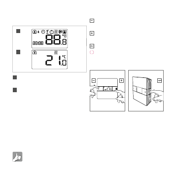
Thermostat control and display
Powering up for the first time
A
After power up, all LCD segments are turned on
for two seconds.
B
After initialization the room thermostat will show
the standard display.
The room thermostat is powering up with
the factory default settings. After a power
failure the thermostat will continue the
operation mode as it was before the power
failure. This will be up to 15 hours if the
unit has been fully powered for 24 hours.
Installers parameter settings are
permanently stored on power failure.
Key assignment
Decrease temperature. Also back in
menu settings
Increase temperature. Also forward in
menu settings
Enter / Exit
Flashing symbols or numbers are
changeable
A
B
AM
PM
1234567
R
S
F
R
+
-
PM
R
40
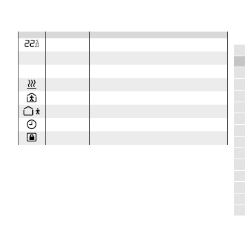
LCD icon
Indicator
Description
Explanation
Temperature
Shows the actual room (R) temperature or the set (S) point temperature.
The set point temperature is your required room temperature
R
Room temperature
The displayed temperature is the current room temperature
S
Set point temperature
The displayed temperature is the required room temperature
Heating active
Heating mode is active
Normal mode
Operation mode normal is active
Reduced mode
Operation mode reduced is active
Time switch program
The thermostat will automatically select operation mode normal and reduced
based on the external time switch
Lock mode
Protect the room thermostat against unauthorized access
41
DE
EN
CZ
ES
FR
GR
HU
IT
NL
PL
RO
RS
RU
SE
TR
Adjusting set temperature
Reducing set temperature
To view the set point temperature only press once
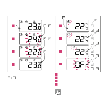
Operational modes
Selection - Standard thermostat
1
Normal operation: Default set point 22ºC
2
Reduced operation: Default set point 18ºC
3
Auto operation: Only with external time switch
4
Operational mode off (optional)
When the Nea is set to OFF there is
automatic frost protection active. If the
R
S
S
R
1
2
3
4
or
or
R
2
3
4
R
R
1
or
or
or
or
42
temperature falls below 5 ºC the heating
valve will be activated.
If an external time switch is activated
and the clock is displayed then the
change in set temperature is temporary.
The set point will return to normal / reduced
on next time switch program change. To
accept changes, press .
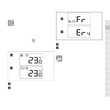
Auto - Standard thermostat
A
Time switch program activ; normal mode
B
Time switch program activ; reduced mode
Display messages
A
Frost protection is active
B
Room temperature out of sensor range
Frost protection display will remain
until any key is pressed.
General function information
Valve protection
To protect the valves the output is turned on
for 5 minutes in every week. This function
stops the valve from getting stuck due to
long periods of inactivity.
Pulse width modulation
Room temperature control is achieved by
A
B
R
R
R
A
B
43
DE
EN
CZ
ES
FR
GR
HU
IT
NL
PL
RO
RS
RU
SE
TR
opening and closing the circuit control
valves for defined times. The opening time
of the valves is determined by the required
energy supply.
PI control
The PI control adjusts the control signal
gradually to the demand of the system, in
order to optimize the control result. This
optimization must be applied very cautiously
in case of surface heating and cooling.
Cleaning your Nea
Only use a soft, dry, solvent-free cloth for
cleaning.
A blown fuse can indicate an error
within your system. Before replacing
the fuse, the system must be checked by
an authorized specialist.
Technical data
Nea H 230 V
Nea H 24 V
Operating voltage
230 V-AC +/- 10 % 24 V-AC + 20 % - 10 %
Max. switch current
0.2 A*
1 A*
Fuse
0.63 A T
1 A T
Safety
Class II
Class III
Max no. of actuators
5 x 3 W
Degree of protection
IP30
Anfi freeze operation
5 °C
Valve protection function 5 min/week
Dimensions frontside
88 x 88 (mm)
Dimensions backside
75 x 75 (mm)
Depth
26 (mm)
Storage temperature
-20 to 60 °C
Ambient temperature
0 to 50 °C
Relative humidity
Max. 80 %, non condensing
* Resistive load
44

© REHAU 954609 de/en/cz/es/fr/gr/hu/it/nl/pl/ro/rs/ru/se/tr 04.2013
www.rehau.com
REHAU AG + Co, Otto Hahn Str. 2, 95111 Rehau, Germany