Full Text Searchable PDF User Manual
www.raycap.com
Installation Instructions:
3315-ALM-RS485
INSTALL INSTRUCTIONS
3315-ALM-RS485


www.raycap.com
©Raycap • All rights reserved
320-1261 Rev.C
Page 3 of 24
INSTALL INSTRUCTIONS
3315-ALM-RS485
Contents
1 Copyright
3
1.1 Disclaimer
3
1.2 Warnings
4
2 Introduction
4
3.1 Prerequisites
4
3.2
Required Tools
4
3.3
Kit Contents
4
4.1
Pre-wiring Preperation Procedure
5
6.1
Removing Strikesorb Modules
7
7.1
Removal of Touch Guard
8
8.1
Removal of Existing Alarm Wiring
9
9.1
Removal of Stand-Offs & Alarm Board
10
10.1
Installation of 3315-ALM-RS485
11
11.1
Installing Alarm Wiring
14
13.1
Installing Complete
21
14.
Supported Configurations
22
1.0
Copyright
©
Raycap, Inc. 2018 - All Rights Reserved
1.1
Disclaimer
The information in this document is subject to change without notice and describes only the product
defined in the introduction of this documentation. This documentation is intended for the use of
Raycap customers only for the purposes of the agreement under which the document is submitted,
and no part may be used, reproduced, modified or transmitted in any form or means without the prior
written permission of Raycap. The documentation has been prepared to be used by professional
and properly trained personnel, and the customer assumes full responsibility when using it. Raycap
welcomes customer comments as part of the process of continuous development and improvement
of the documentation.
This product is suitable for OSP.
Raycap has made all reasonable efforts to ensure that the instructions contained in this document
are adequate and free of material errors and omissions. Raycap will, if deemed necessary, explain
issues which may not be covered by this document.
The contents of this document are subject to revision without notice due to continued progress in
methodology, design and manufacturing. Raycap shall have no liability for any error damage of any
kind resulting from the use of this document.
www.raycap.com
©Raycap • All rights reserved
320-1261 Rev.C
Page 4 of 24
3315-ALM-RS485
INSTALL INSTRUCTIONS
1.2
Warnings
Before using the product, read all instructions and cautionary markings on the product and on
any equipment connected to the product.
CAUTION – Unless otherwise noted, product usage that is not recommended or sold by the
product manufacturer can result in risk of fire, electric shock, or injury to persons.
CAUTION – Do not operate the product if it has been damaged in any way. Return damaged
products to their manufacturer for repair or replacement.
ATTENTION – Electrostatic sensitive devices. ESD mitigative procedures, such as wearing
wriststraps are to be used during installation and maintenance.
2.
Introduction
In a split Radio Base Station (RBS) architecture the typical RBS consists of a Base Band Unit
(BBU) and Remote Radio Heads (RRH) connected by cabling. Power to the RRH is provided
through copper cables traveling from the base station to the top of the tower or roof top. This
creates a conductive path, making the active equipment at the top and the base of the site
vulnerable to damage by direct lightning strikes. Protection systems installed in front of both
the BBU and the RRH must be able to withstand direct lightning currents in order to protect
the sensitive equipment. Raycap’s RRH solutions featuring Strikesorb® SPD technology
significantly enhance the reliability & availability of the RRH site by providing superior
electrical protection at the RRH and BBU, and also enable flexible fiber optic and power cable
management solutions.
The 3315-ALM-RS485 is suitable for installation for Network Telecommunications Facilities,
(Central Office), Outside Plant (Remote Termainal Facilities), and locations where the NEC
applies (Customer Prem Locations).
3.1
Prerequisites
Installers of Raycap’s RRH surge protective and fiber/power management solutions must be
industry professionals who have attended training on the proper installation of the equipment
by Raycap and/or the mobile operator. Installers are required to read this installation guide
thoroughly prior to installation of the Raycap RRH protection equipment.
Installers shall obey all general and regional installation and safety regulations related to
work on high voltage installations, as well as regulations covering correct use of tools and
personal protective equipment. Use this equipment only for the purpose specified by the
manufacturer. Do not carry out any modifications or fit any parts that are not recommended by
the manufacturer. This could cause electric shock or other injuries.
3.2
Required Tools
#2 Phillips head screwdriver
ESD Strap
Torque wrench
¼” Nut Driver
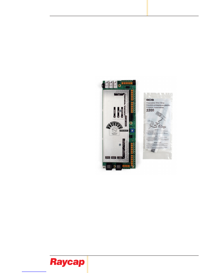
3.3
Kit Contents
Alarm/Voltmeter PCB Assembly
Anti-Static Wrist Strap
Installation Instructions
For conditions other than those described above, please contact a Raycap Account
Representative at +1 (208) 777-1166, (800) 890-2569, info@raycap.com, or www.raycap.com
www.raycap.com
©Raycap • All rights reserved
320-1261 Rev.C
Page 5 of 24
INSTALL INSTRUCTIONS
3315-ALM-RS485
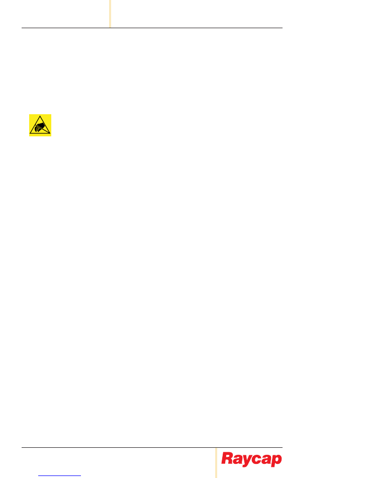
Pre-wiring Preparation Procedure
4.1
Ensure the lanyard from enclosure lid to
enclosure base is secure.
Note:
Use metal mounting frame to
secure hoist when lifting to tower top.
Warning:
Holes in lid for lanyard and
padlock must NOT be used as hoist
locations.
4.2
WARNING –
Disconnect or disable the
DC power source to the product prior to
beginning this installation.
(Installed cables and wires not shown for clarity)
4.3
Open up clamps on all sides of the
enclosure cabinet by lifting the hinged
clamp tabs.
4.4
Carefully slide the copper dome over the top
of the assembly and set aside.
4.5
To access power, fiber and alarm wire
connections, unclasp 1/4 turn latches,
then fold down fiber tray.
www.raycap.com
©Raycap • All rights reserved
320-1261 Rev.C
Page 6 of 24
3315-ALM-RS485
INSTALL INSTRUCTIONS
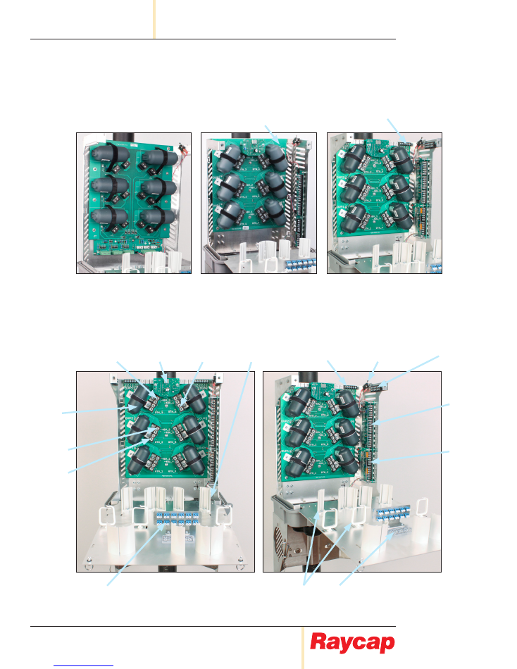
Return
Connection
Fiber Connection
Panel
Fiber
Management
Fiber Panel
Label
Alarm
Board
Alarm
Connector
Voltage Monitor
Connections
Voltage Monitor
Pass-Thru
Connections
Moisture
Sensor
Intrusion
Sensor
Strikesorb
Module
-48V
Connection
Voltage
Monitor
Return
Connection
-48V
Connection
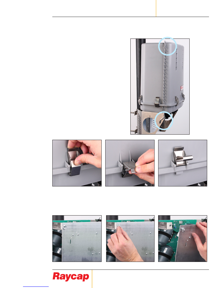
Identifying generation of 3315
5.1.
Generation 1
NOT Compatible with
3315-ALM-RS485
Generation 2
Compatible with
3315-ALM-RS485.
Requires steps starting on
page 18.
Generation 3
Compatible with
3315-ALM-RS485.
Proceed to Step 6.1
Does NOT have
Voltage Monitor
Connections
Voltage Monitor
Connections
www.raycap.com
©Raycap • All rights reserved
320-1261 Rev.C
Page 7 of 24
INSTALL INSTRUCTIONS
3315-ALM-RS485
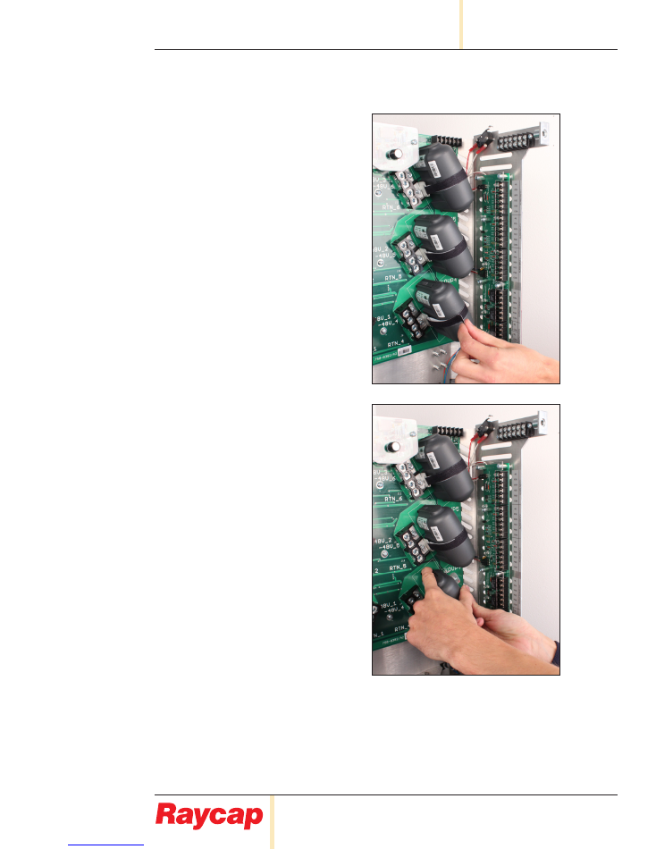
Removing Strikesorb Modules
6.1
Remove the 3 Strikesorb Modules
located on the right side of the main
PCB.
6.2
Release and remove Velcro strap
from Strikesorb module.
6.3
Grab the Strikesorb module by ends
and depress lever on both sides.
6.4
Rock the Strikesorb module
side to side, and pull it out.
Note: You have to overcome a strong
spring contact to remove module.
www.raycap.com
©Raycap • All rights reserved
320-1261 Rev.C
Page 8 of 24
3315-ALM-RS485
INSTALL INSTRUCTIONS
Procedure
Removal of Touch Guard
7.1
Using a #2 Phillips-head
screwdriver,
Remove 7 screws
securing the touch guard.
Remove touch guard and set aside.
Touch guard will not be used
for 3315-ALM-RS485 kit installation.
7.2
Remove the 2 labels from the frame as indicated.
Remove
Labels
www.raycap.com
©Raycap • All rights reserved
320-1261 Rev.C
Page 9 of 24
INSTALL INSTRUCTIONS
3315-ALM-RS485
Procedure
Removal of Existing Alarm Wiring
8.1
NOTE –
Label each alarming wire to ensure proper
connection when reinstalling to 3315-ALM-RS485 PCB.
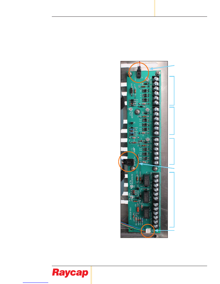
8.2
Depress the release tabs on the
Intrusion and Power Connectors
before pulling on the connector,
Remove all wires
connected to
the alarm board pictured below.
Alarm Inputs 1
Intrusion Alarm
Alarm Inputs 2
Alarm Inputs 3
Power
Alarm Outputs
Water Ingress Alarm
www.raycap.com
©Raycap • All rights reserved
320-1261 Rev.C
Page 10 of 24
3315-ALM-RS485
INSTALL INSTRUCTIONS
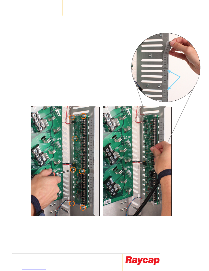
Procedure
Removal of Stand-Offs and Alarm Board
9.1
NOTE –
Label each alarming wire to ensure proper
connection when reinstalling to 3315-ALM-RS485 PCB.
9.2
Using a ¼” nut-driver,
Remove 7 stand-offs
securing the PCB to the frame.
Remove PCB and set aside.
The stand-offs and this PCB will not be used
for 3315-ALM-RS485 kit installation.
www.raycap.com
©Raycap • All rights reserved
320-1261 Rev.C
Page 11 of 24
INSTALL INSTRUCTIONS
3315-ALM-RS485
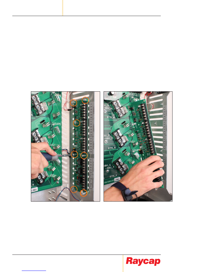
Procedure
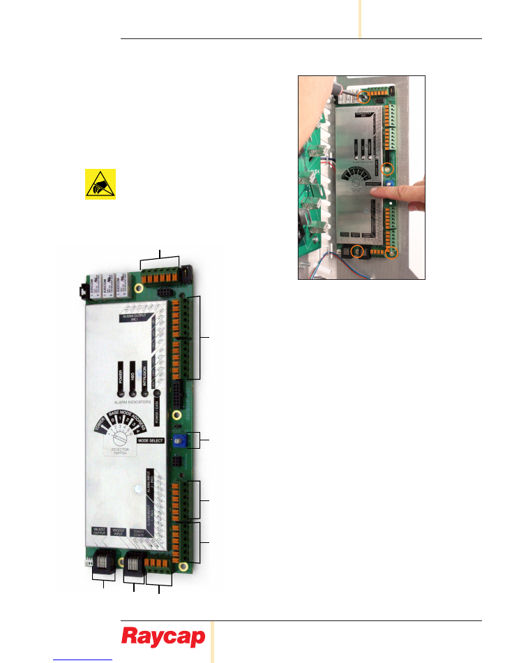
Installation of 3315-ALM-RS485
10.1 Align new alarm board to frame.
Using a #2 Phillips-head screwdriver,
secure 4 screws
.
ATTENTION - Ensure ESD wriststrap is used
Electrostatic sensitive devices. ESD mitigative
procedures, such as wearing wriststraps are to
be used during installation and maintenance.
7.0
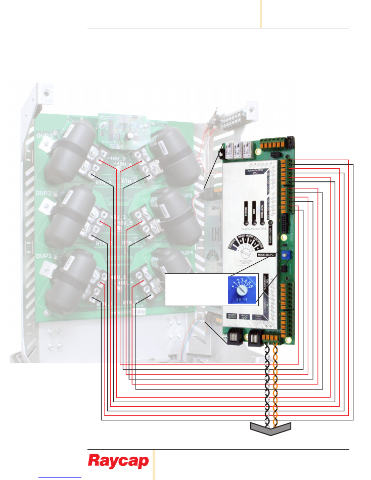
Installing Alarm Wiring
A.
Alarm Output to BTS: Outputs for Intrusion, H2O, and Power
B.
Legacy: parallel voltage monitor wire connections
C.
Rotary Switch for Base Mode Operation. Place rotary switch to
position “2, 3, 4, 5, or 6” which corresponds to base mode
address “0, 1, 2, 3, or 4”. If in daisy chain configuration, place
selector switch to the next base mode address.
Place rotary switch to “
•”
or “1” for Tower Top Mode Operation.
D.
Legacy alarm wire connections 2: For Daisy Chain
E.
Legacy alarm wire connections 1: For Intrusion, H2O, and Power
F.
Base Communication: Base RS485 communication input from
tower, 2-twisted pair (4 wires total)
G.
VBoost Input: Optional ethernet daisy chain input
H.
VBoost Output: Optional ethernet output to daisy chain / VBoost
A
B
C
D
E
H
G
F
www.raycap.com
©Raycap • All rights reserved
320-1261 Rev.C
Page 12 of 24
3315-ALM-RS485
INSTALL INSTRUCTIONS
Procedure
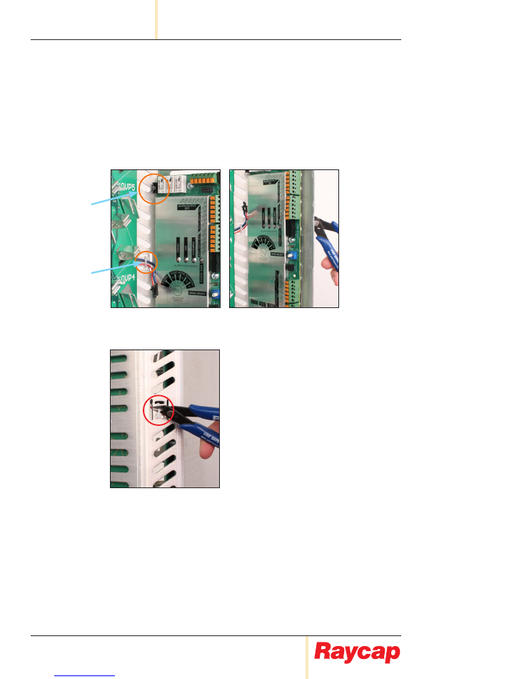
Installation of 3315-ALM-RS485 (continued)
10.2 The power wire is secured to frame. In order for the power wire to reach the connection
terminal, the cable tie must be clipped.
10.3 From the backside of the unit, carefully
clip the cable tie
to allow cable length to reach
the Power wire connection terminal. This will minimize the chance of damaging the
power wire.
Power Wire
connection terminal
Power Wire
(secured to frame)
Figure 10.2
(indicating to clip cable-tie on
the back-side of unit)
Figure 10.3
clipping cable-tie on
back-side of unit
www.raycap.com
©Raycap • All rights reserved
320-1261 Rev.C
Page 13 of 24
INSTALL INSTRUCTIONS
3315-ALM-RS485
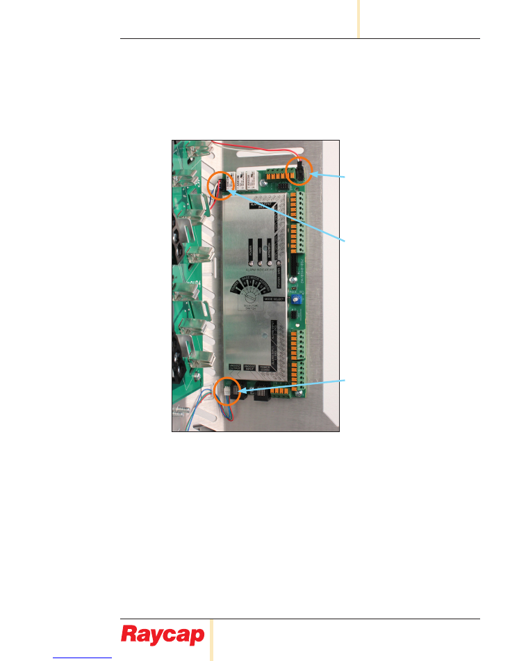
Procedure
Connecting wires to 3315-ALM-RS485
10.4 Connect the Power Intrusion
and H
2
O wires.
Intrusion Alarm
Power
Water Ingress Alarm
www.raycap.com
©Raycap • All rights reserved
320-1261 Rev.C
Page 14 of 24
3315-ALM-RS485
INSTALL INSTRUCTIONS
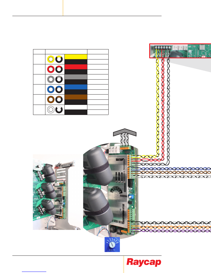
Alarm
Outputs
to BTS
Note:
Base Mode Address “0”
Position “2”
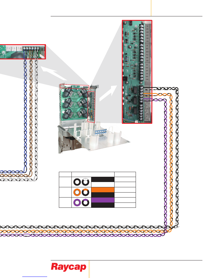
11.1
Alarm connections for 3315-ALM-RS485
RVZDC-3315-PF-48 at the Tower Top connected to RVZDC-3315-PF-48 with Retrofit Kit at the base.
Pair
Color
Alarm Input
1
Yellow
RTN (1)
Black
-48V (1)
2
Red
RTN (2)
Black
-48V (2)
3
Slate
RTN (3)
Black
-48V (3)
4
Blue
RTN (4)
Black
-48V (4)
5
Brown
RTN (5)
Black
-48V (5)
6
White
RTN (6)
White/Black
-48V (6)
Base Unit
Voltage Monitoring on Main PCB
www.raycap.com
©Raycap • All rights reserved
320-1261 Rev.C
Page 15 of 24
INSTALL INSTRUCTIONS
3315-ALM-RS485
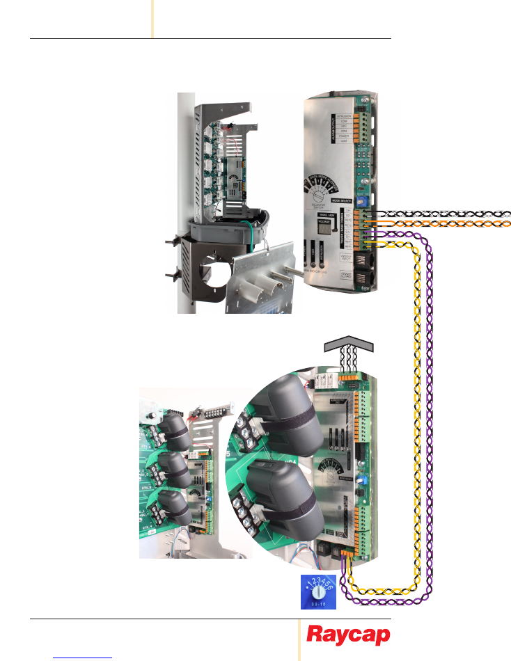
Alarm
Outputs
to BTS
Note:
Base Mode Address “0”
Position “2”
Pair
Color
Alarm Input
1
Black
-48V
Black/White
RTN
2
Orange
INTR
Black
H
2
O
3
Violet
PWR
Black
COM
Voltage Monitoring on Main PCB
3315 Tower Top Unit
Alarm Board
www.raycap.com
©Raycap • All rights reserved
320-1261 Rev.C
Page 16 of 24
3315-ALM-RS485
INSTALL INSTRUCTIONS
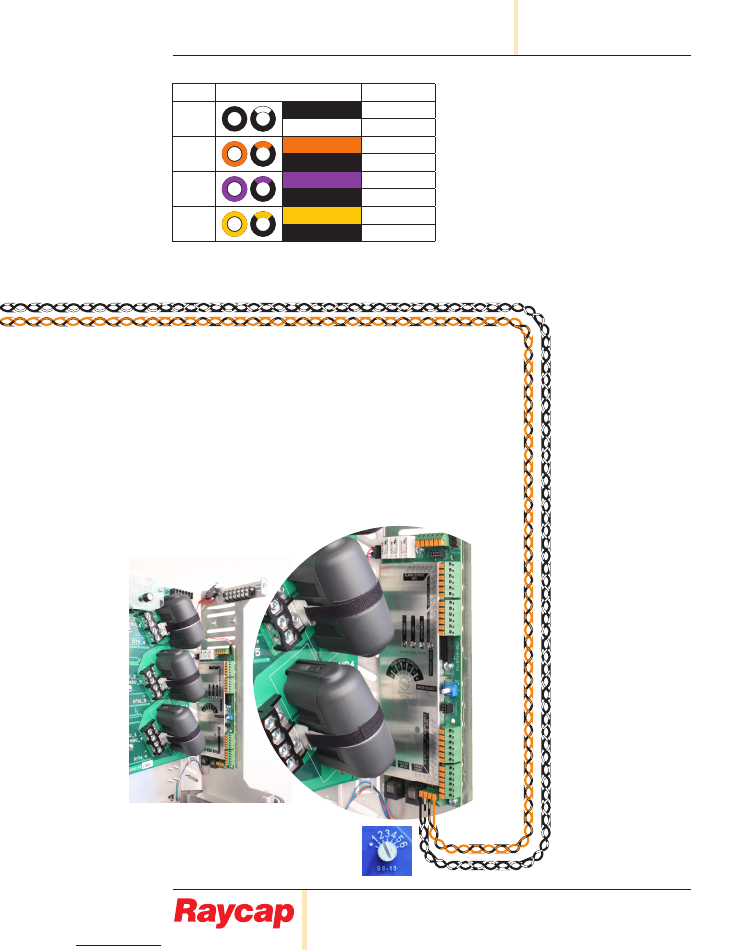
Note:
Base Mode Address “1”
Position “3”
Note:
Base Mode Address “0”
Position “2”
Alarm
Outputs
to BTS
11.2
Alarm connections for 3315-ALM-RS485
RVZDC-6627-PF-48 at the Tower Top connected to (2) RVZDC-3315-PF-48 with Retrofit Kits at the base.
Tower
Base “1”
www.raycap.com
©Raycap • All rights reserved
320-1261 Rev.C
Page 17 of 24
INSTALL INSTRUCTIONS
3315-ALM-RS485
Note:
Base Mode Address “1”
Position “3”
Note:
Base Mode Address “0”
Position “2”
Alarm
Outputs
to BTS
Pair
Color
Data
1
Black
D2+
White/Black
D2-
2
Orange
REF2
Orange/Black
REF2
3
Violet
D1+
Violet/Black
D1-
3
Yellow
REF1
Yellow/Black
REF1
Base “0”
www.raycap.com
©Raycap • All rights reserved
320-1261 Rev.C
Page 18 of 24
3315-ALM-RS485
INSTALL INSTRUCTIONS
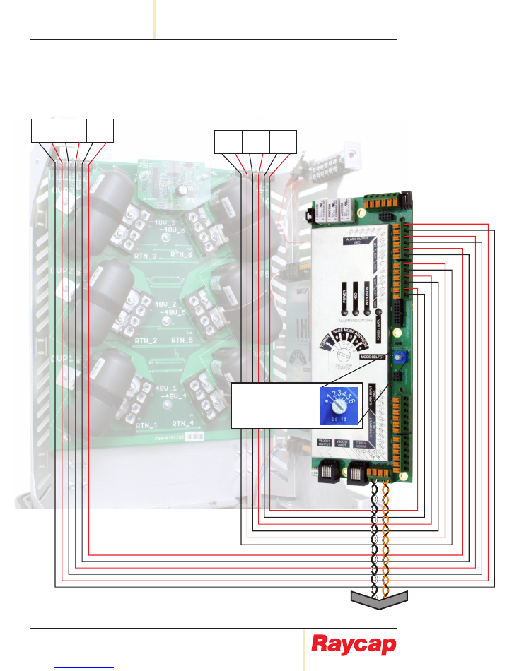
11.3
Alarm connections for 3315-ALM-RS485.
Third Generation
RVZDC-3315-PF-48 installed on Tower Top.
Note:
Set to “1” for Tower Top
Mode Operation
Outputs
to Base
RTN
|
-48V
1
2
3
RTN
|
-48V RTN
|
-48V
RTN
|
-48V
1
2
3
RTN
|
-48V RTN
|
-48V
www.raycap.com
©Raycap • All rights reserved
320-1261 Rev.C
Page 19 of 24
INSTALL INSTRUCTIONS
3315-ALM-RS485
11.4
Alarm connections for 3315-ALM-RS485.
Second Generation
RVZDC-3315-PF-48 installed on Tower Top.
Outputs
to Base
Note:
Set to “1” for Tower Top
Mode Operation
www.raycap.com
©Raycap • All rights reserved
320-1261 Rev.C
Page 20 of 24
3315-ALM-RS485
INSTALL INSTRUCTIONS
Installing a Strikesorb Module
12.1
Reinstall the 3 Strikesorb modules that were removed in Step 6.1.
Installation Complete.
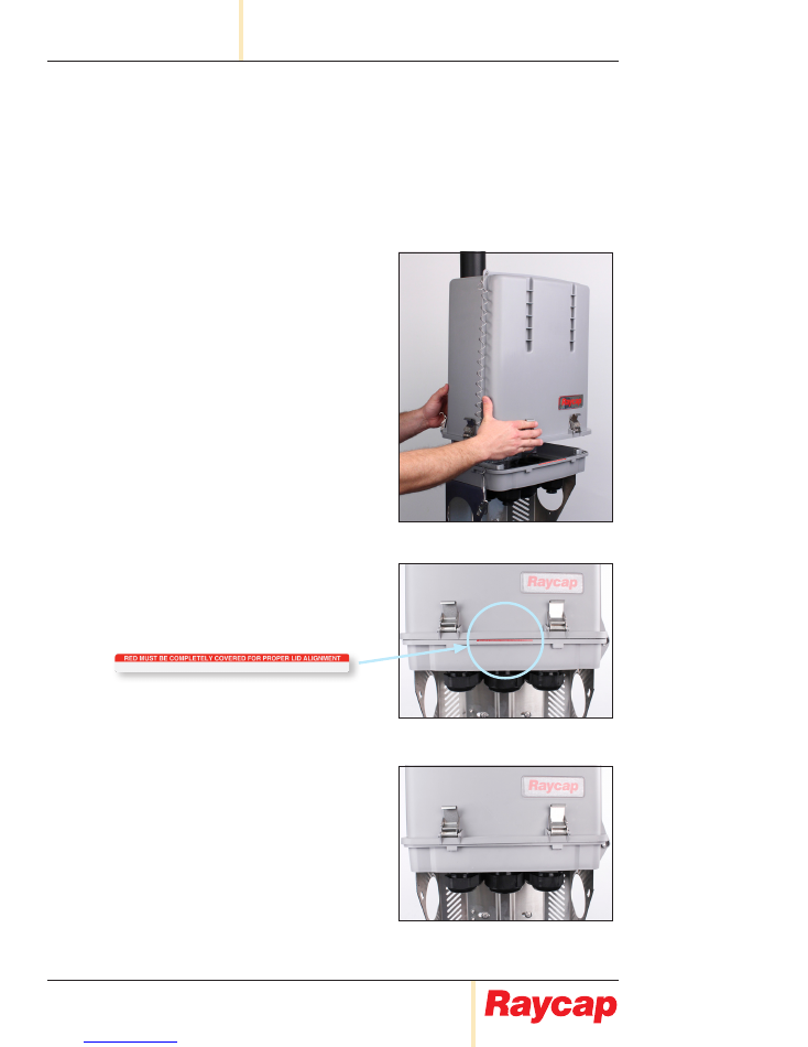
Closing and Securing Unit.
13.1
Slide enclosure lid into place.
13.2
As pictured, Lid IS NOT
properly aligned.
Red must be completely covered for
proper lid alignment.
13.3
As pictured, Lid IS properly aligned.
www.raycap.com
©Raycap • All rights reserved
320-1261 Rev.C
Page 21 of 24
INSTALL INSTRUCTIONS
3315-ALM-RS485
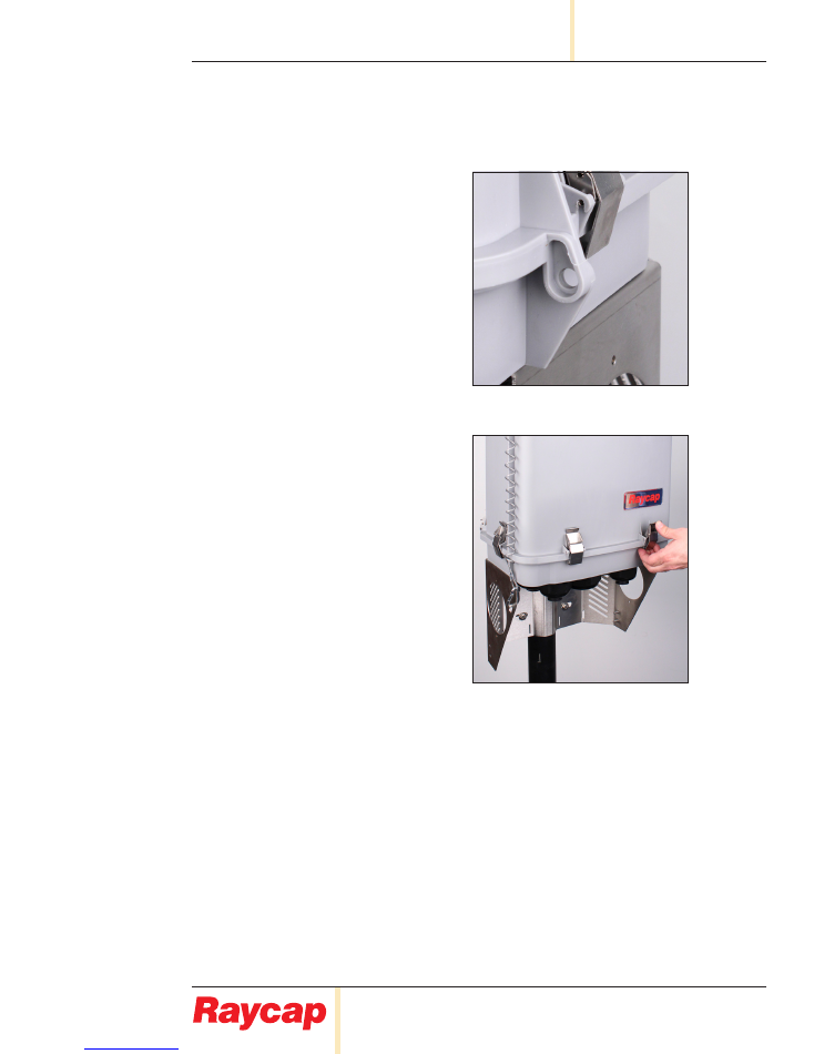
13.4
If installation requires padlocks, (not
provided) secure “bottom right” of
enclosure.
Note:
If padlock holes are NOT
aligned, the lid is NOT properly
aligned.
13.5
When alignment of lid is comfirmed,
close and secure all clamps.
Installation complete.
www.raycap.com
©Raycap • All rights reserved
320-1261 Rev.C
Page 22 of 24
3315-ALM-RS485
INSTALL INSTRUCTIONS
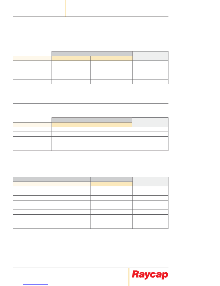
14. Supported Configurations
(
Note:
Any combination of these supported configurations, can be used in Daisy Chain.)
12 OVP Rack Configurations (Base):
Unit Connected at Top
Configuration
Supported?
Base Unit 1
Tower 1
Tower 2
4520
6627
NONE
YES
4520
3315 (with Retrofit)
NONE
YES
4520
3315 (with Retrofit)
3315 (with Retrofit)
YES
4520
6627
6627
NO
4520
6627
3315
NO
“4520” = 12 OVP Rack | “2260” = 6 OVP Rack | “6627” = 12 OVP Dome | “3315” = 6 OVP Dome
12 OVP Dome Configurations (Base):
Unit Connected at Top
Configuration
Supported?
Base Unit 1
Tower 1
Tower 2
6627
6627
NONE
YES
6627
3315 (with Retrofit)
NONE
YES
6627
3315 (with Retrofit)
3315 (with Retrofit)
YES
6627
6627
6627
NO
6627
6627
3315
NO
“6627” = 12 OVP Dome | “3315” = 6 OVP Dome
“with Retrofit” = Retrofit Alarm Board installed
6 OVP Rack/Dome Configurations (Base):
Unit Connected at Base
Unit Connected at Top
Configuration
Supported?
Base Unit 1
Base Unit 2
Tower 1
3315 (with Retrofit)
3315 (with Retrofit)
6627
YES
3315 (with Retrofit)
3315
6627
YES
2260 (with Retrofit)
2260 (with Retrofit)
6627
YES
2260 (with Retrofit)
2260
6627
YES
3315 (with Retrofit)
NONE
3315
YES
2260 (with Retrofit)
NONE
3315
YES
3315
3315
6627
NO
2260
2260
6627
NO
6627
6627
6627
NO
“4520” = 12 OVP Rack | “2260” = 6 OVP Rack | “6627” = 12 OVP Dome | “3315” = 6 OVP Dome
“with Retrofit” = Retrofit Alarm Board installed


www.raycap.com
©Raycap • All rights reserved
320-1261 Rev.C
Page 24 of 24
3315-ALM-RS485
INSTALL INSTRUCTIONS