Full Text Searchable PDF User Manual
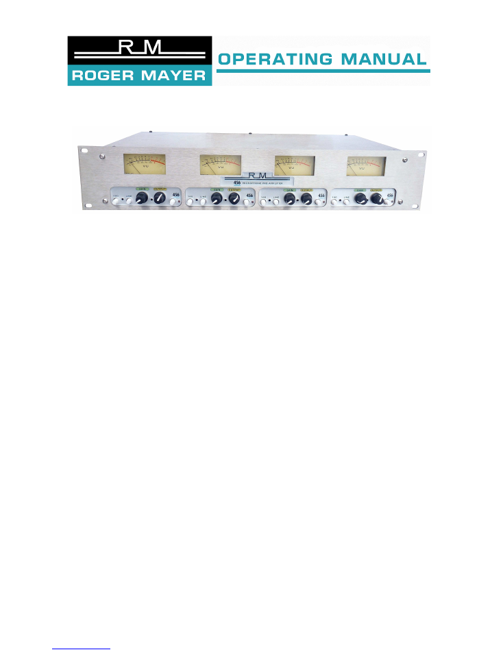
456 Microphone Pre-Amplifier
Features:
•
Golden Era Analogue Microphone Pre-Amplifier Design
•
456HD® Analogue Tape Simulation
•
Discrete Ultra Low Noise Class A Design
•
Ultra Wide Bandwidth
•
Transformer Fully Balanced Inputs and Outputs
•
22 way stepped Microphone Gain Control
•
22 way stepped Output Gain Control
•
Line Input Switch with Output Gain Adjust
•
180º Phase Reversal Switch
•
Accurate Wide Band VU with Calibration Adjustment
•
456HD® Output Level Adjustment
•
Gold Plated XLR Connectors
•
Triple Shielded 6 layer PC Card construction
•
Ultra low noise 48V Phantom Supply
•
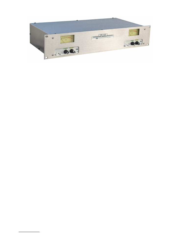
2-Channel version available upgradable to 4-Channel
Introduction:
Roger Mayer is proud to announce the latest evolution from a long series of award winning
pre-amplifier designs. It began its development history in 1968 whilst I was working in
Olympic Studios, London. The development continued with my move to New York and the
formation of Roger Mayer Electronics Inc with designs of Recording Studio Desks, RM58
Limiters, RM 68 Noise Gates, Mastering Equalisers and Location Recorders all using
evolutions of our design. These products were supplied to many top Studios in the USA
and Europe. The transparency and detail from our wideband design configuration is
considered by many to be the ultimate 3D sounding pre-amplifier and can be heard on
many landmark recordings of all kinds of musical genres. The phase accuracy and lack of
time smearing artefacts is unbeatable and we welcome audio comparison to other
products. The innovative addition of being able to add the acclaimed 456HD® Analogue
Tape Simulation provides a full analogue signal path from Microphone straight into the
DAW. The result is a Golden Era Signal path for the digital world.
History:
The development of Microphone Pre-Amplifiers that were used in recording consoles
before 1970 all used discrete configurations that in many ways were derived from the
tube circuits previously used. In fact the introduction of silicon low noise transistors did
not begin until around 1968. The germanium transistors previously used were not that
quiet and had to be carefully selected to obtain good performance.
The semiconductor industry was changing very quickly back then and had been driven
forwards to a large extent by the USA and the demands of the NASA Space Programs
and the Apollo Program to “Land a Man on the Moon”. Integrated circuits had not yet
been commercially released and any previous operational amplifiers relied on discrete
and hybrid construction. The manufacture of ICs requires a very pure silicon wafer which
as a secondary spin off made low noise discrete devices with both PNP and NPN types
available for the first time. Footprint and line width reduced dramatically to enable all the
circuit components to be shrunk and fitted on the ever decreasing die size used in
making ICs. It soon became apparent that this small die size came with several
important performance limitations with regards to stability, power dissipation and high
frequency phase performance. Also the need for dual complimentary tracking power
supply rails. The almost universal adoption of long tailed pair input stages in the IC also
became popular with this new manufacturing technology and is very beneficial if you are
using the ICs for instrumentation and scientific applications. This input stage
configuration however does not produce the optimum audio performance for ultimate
audio quality. ICs were much cheaper than the discrete equivalent circuit and were used
in commercial consumer products with the marketing people using their skill to
manipulate public perception of this new technology much in the same way as the word
Digital is nowadays used to imply quality when in actual fact the resulting audio quality
produced is inferior to the Analogue information it is derived from.
The top recording studios however in the early 1970’s mostly built their own custom
recording consoles using discrete methods and can be thought of in the same way as F1
Racing Car Manufacturers who are interested in obtaining a technological advantage by
developing and setting new performance standards. The recordings produced by those
top world studios featured on so many famous legendary artist’s albums are considered
today the Benchmark and Holy Grail of Recordings eg: Jimi Hendrix - Axis Bold as Love
(Olympic Studios - London), Stevie Wonder: Innervisions, Music of My Mind (Electric
Lady Studio, Record Plant - New York), Rolling Stones, Jumpin Jack Flash etc. (Olympic
Studios - London).
The concept of the most accurate and direct possible path from microphone to the
recorder was always followed in the quest for ultimate quality.
Using up to a 17 ICs in a chain found in some of today’s recording signal paths of
course degrades the signal as all op-amps will never perform up to their theoretical
performance and their errors all add up. This becomes ever apparent when making a
comparison to a direct path approach design

Most modern designed products are marketed on price then features with performance
reduced to what can be acceptable to the public. This is not the State of the Art and
should never be considered as such. After all a mass produced car is never considered
to be racing car.
The 456 Microphone Pre-Amplifier uses the expensive discrete approach to audio
performance without any ICs in the Audio Path and sets the current State of the Art
performance using today’s highest quality parts and techniques all evolved from the
ground breaking and pioneering techniques we developed back then.
The detail, phase and frequency response from our direct approach has to be heard and
compared to other pre-amplifiers.
CHANNEL TECHNICAL INFORMATION:
The following details apply for every channel of the 456 and the 2 Channel model can
easily be upgraded to the 4 Channel model. Each channel has its own multistage
onboard power supply circuits providing the required voltages and also providing signal
isolation from the other channels to minimise crosstalk. A single 48V World Power
Supply Desktop Adaptor is supplied and is conforms to the latest ECO and Safety
Regulations.
TRANSFORMER BALANCED INPUTS AND OUTPUTS
We manufacture in house our own custom transformers using Ferrite Cores with wide
bandwidth material specification to ensure ultimate high frequency, phase response and
hum rejection. There is no better way to connect a microphone into an amplifier than by
using a high bandwidth quality transformer. Perfect isolation and safety can be obtained
in the most demanding situations with no chance of destroying your microphone pre-amp
by plugging a microphone in.
Phantom Powering
can be left on as traditionally always
was done without damage to the microphones whether they are Ribbon, Dynamic or
Condenser. Just make sure your microphone cables are correctly wired and of the
highest quality. The modern myths about turning the phantom on and off have been
discussed and dismissed and began with the introduction of electronically balanced input
circuits with phantom power issues.
Electronically balancing an input with a multiple IC configuration is cheaper for sure but
then you have introduced a convoluted signal path right before you start to amplify it.
Also be aware that audio signals are not symmetrical about the zero axis and also differ
with every 180° so electronic balancing will always introduce input errors.
So it makes sense to have a direct balanced transformer path to the pre-amplifier.
MICROPHONE INPUT TRANSFORMER:
This has been especially designed to
interface and accommodate high output condenser capsules as well as low output ribbon
types. SPL levels of 150dB from an AKG 414 will not overload it.
PHANTOM POWERING:
is from carefully matched pairs of 6K8 resistors with a
tolerance typically. 0.02%. Each channel provides a 4-stage filter network producing
175dB of noise reduction. Virtual DC operation to the microphone is thus ensured.
LINE INPUT TRANSFORMER:
The transformer is capable of accepting high levels in
excess of +35dBu.
OUTPUT TRANSFORMER:
This has an electronic specification that is perfectly matched
to DAW input specifications. The headroom provided is at least 24dB above nominal
operating conditions.

MICROPHONE PRE-AMP
This is a 2 stage design using both PNP and NPN low noise transistors in our proprietary
configuration. The
GAIN
is controlled by a 22way stepped conductive plastic
potentiometer so as not to cause any clicks or drop outs but also have recall ability.
The
GAIN CONTROL
is used in conjunction with
OUTPUT CONTROL
to quickly and
easily set the required level. The total range of
GAIN CONTROL
with the 2 CONTROLS
is 65dB.
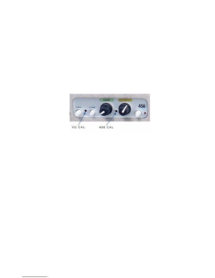
180° Phase Reversal Switch:
This is provided to flip the phase of the microphone when
needed.
OUTPUT AMPLIFIER
This is also a 2 stage design as above. The
LINE INPUT
can be directly routed to this
stage by activating the line select switch and is by default connected to the pre-amp
stage
.
OUTPUT CONTROL
is also a 22way stepped conductive plastic potentiometer and
has a range of about 14dB to offer fine gain adjustment to both operational modes of line
or pre-amp with 10dB of overall gain available for the
LINE INPUT
.
VU METER:
This is illuminated and driven from a high input impedance custom
designed meter driver circuit. The meter gives very good ballistic response with all types
of program material and is easy to use when recording.
High Accuracy
of +/- 0.2dB 20Hz to 80Khz.
VU METER CALIBRATION:
This can be adjusted with a screwdriver through a small
hole in the front panel to activate a 22 Turn Preset Potentiometer. The sensitivity can
then be set to your preferred operational set up standards. Factory default setting is
0VU = +4dBu
DUAL VU METER MODES:
They can be accessed on the PC Card and set by moving
a Jumper.
Mode 1:
This is the factory default setting with the VU Meter monitoring the Pre-Amplifier
Output before the 456HD® Tape Simulation so you can judge with the VU Meter how
hard you are pushing the 456HD®.
Mode 2:
This is the optional setting to monitor the output after the 456HD®
Tape Simulation and will follow any output offset you set for the 456HD® when it is
active.
456HD® TAPE SIMULATION ANALOGUE DYNAMICS PROCESS:
This can activated with the switch and LED Status provided.
Output Level Calibration
: The maximum level of simulated tape saturation or dynamic
analogue effect can easily be adjusted so that the peak level reached does not ever
exceed 0dBFS and thus enter digital distortion. Front panel screwdriver access enables
setting this 22 turn control for the various operating standards occurring with DAW
software or outboard converters. The factory default setting is set at +6dB above 0 VU
so that the peak levels reach about -3dBFS with the current Avid Pro-Tools default
setting for 0VU. Please check your supplier’s manuals for calibration info regarding your
equipment.
Please read the page on the 456HD® process for more detailed information.
MICROPHONE RECORDING OPERATION:
So once the 456® Level has been adjusted for your system and you are monitoring in
VU Mode 1 (Default), simply plug in your choice of Microphone set the
OUTPUT
CONTROL
to 12 o’clock and adjust the GAIN control so that a reading around 0 VU is
obtained. Further fine adjustments can be made with the
OUTPUT CONTROL.
You can
then activate the 456HD® Process to hear the difference and then hear the changes as
you increase the
VU READING
just like when recording with tape as the record level
progressively saturates the tape.
LINE INPUT RECORDING OPERATION:
The Line Input function uses a separate transformer and XLR Connector and when the
Line Switch is pressed in this input is selected and the OUTPUT control sets the level
required. Up to 10dB of Gain is available and about 3dB of loss to enable ease of use.
Direct access to the 456HD® can then be made for use in other recording or mixing
scenarios.
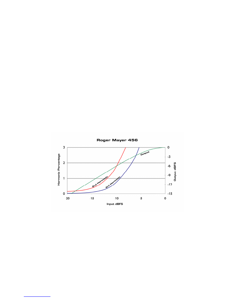
456HD® ANALOGUE DYNAMICS PROCESS:
The 456HD® Analogue Dynamics Process is an innovative new way to experience
modern dynamic and harmonic control in real time with zero latency. It was inspired by
the desirable qualities of tape recording and can reproduce their dynamics and
harmonic properties accurately plus improves the overall dynamic performance of
Digital Recording. After 1 year of testing and development with some top producers
from the UK and being featured on many records it has been recognised that this
process is a game changer and not to be thought of as just another tape emulator. It
brings a far more sophisticated approach to dynamic control and its performance
exceeds that of any tape recorder previously produced now setting a new benchmark.
The ultra high speed analogue processing will effectively improve the dynamics both
when using it as a pre-recording analogue processor before a conventional DAW and
also in post playback from the DAW. Live recording or tracking using multiple
instances of the 456HD® are very beneficial for Drum, Vocal and Instruments and in
many instances obviate the need for further limiting to control input levels. What the
456HD® Process brings to the table cannot be duplicated by any digital plug-in
because all of the difficult ultra high speed control of the source signal has been taken
care of by using the 456HD® so the Digital Recording simply put sounds much better.
So as they say give it a listen.
The 456 circuit used in the 456 Microphone pre-amplifier is exactly the same as in our
other models but does not have the equaliser section so it is perfect for recording with
the minimum of fuss during setup. The BYPASS function being very useful.
For full information please see our website and download the manual.
http:www.roger-mayer.co.uk/456manual.pdf

TECHNICAL SPECIFICATION
The audio signal path is completely Class A with a very high bandwidth. The -3dB
point has been set to above 100Khz. The low end extends to below 10Hz.
Peaks are accurately high speed manipulated with ease and maintain the original
phase position in the waveform. This fact can be observed using the latest high speed
storage oscilloscope technology.
This is a completely discrete analogue design hand built using only selected low noise
transistors, low noise metal film 1% resistors, plastic film capacitors from the World’s
top manufacturers all combined in a design to provide ultimate studio quality audio.
Gold Plated Neutrik XLR connectors are used, LED Status Indication and Custom
Conductive Plastic 22 way Stepped Potentiometers manufactured for best tracking
accuracy.
A 6 layer multi layer PC Card provides full shielding for all circuit traces with the
Ground and Power Planes all contributing to outstanding high frequency phase
performance and stability. The enclosure manufactured from stainless steel completes
the 3 faraday cage triple shielding design necessary in today’s RF congested
environment.
The 48V DC input power is further regulated and filtered onboard to provide virtual
battery performance and the lowest possible noise under all conditions.
Microphone Input Sensitivity:
-75dBV to -10dBV
Line Input Level:
Nominal +4dBu Balanced
Line Input Impedance:
10K
Operating Output Level:
Nominal +4dBu Balanced
Output Level Noise (LINE):
-118dBu
Output Impedance:
100ohms Balanced
Output Load Impedance:
10K or greater
456HD® Dynamic Range
:
96dB
Headroom:
Maximum Line Input level +35dBm – Internal Headroom 25dB
Size:
Standard 2U Rack Size – 483 x 90 x 250mm (19 x 3.5. x 10in).
Weight:
4.0Kg
Power Requirements:
+48V DC regulated
Universal World AC / DC Switching Adaptor Supplied
www.roger-mayer.co.uk


