Full Text Searchable PDF User Manual
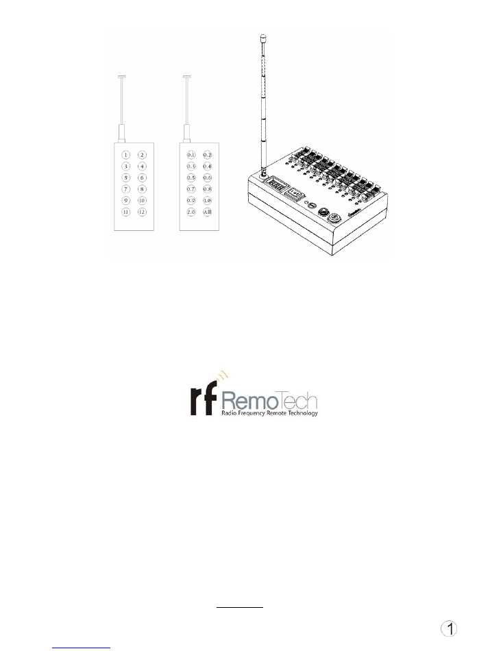
MS12Q
Wireless Firing System
For Pyrotechnics and Fireworks Show
RFRemotech Radio Frequency Remote Technology
Remote Control Products, Remote Controllable Service
Warnings:
The purpose of this device is to cause the ignition of fireworks. Fireworks are explosives and may cause
personal injuries or death to yourself or others, including spectators. You are responsible for the safe and
legal use of this device according to the laws and regulations of your country and/or state/province/district.
RFRemotech is not responsible for illegal or unsafe use of this device. The buyer/user assumes all
responsibility and liability in the use of this device and further agrees, by purchase and/or use of this device,
to indemnify and hold harmless RFRemotech against all liability for injury, loss, or damage direct or
consequential arising out of the use of, or inability to use this device.
You must perform the safety tests (Page 4) every time you use the system.
Model:RF12A
Contents
Warnings------------------------------------------------------------------------------------
P1
Contents-------------------------------------------------------------------------------------
P2
A. Description----------------------------------------------------------------------------------------------
P2
1) Transmitters -------------------------------------------------------------------------
P2
2) Firing Module ------------------------------------------------------------------------
P3
B. How the system works in Two Different Firing Modes-------------------------------
P3
1) Use Transmitter A for Dividual Firing mode---------------------------------------
P3
2) Use Transmitter B for Interval Firing Mode----------------------------------------
P3
C. Before Attaching E-matches/Igniters--------------------------------------------------
P3
1) Installing or Connecting Batteries--------------------------------------------------
P3
2) Safety Tests --------------------------------------------------------------------------
P4
D. Some Available Functions---------------------------------------------------------------
P4
Learn Codes / Clear Codes -------------------------------------------------------------
P4
Test---------------------------------------------------------------------------------------
P4
Arm---------------------------------------------------------------------------------------
P5
Low Power Alarm------------------------------------------------------------------------
P5
Digital Readout Meter-------------------------------------------------------------------
P5
A. Description
:
Firing Module FCC & CE
certified.
OOK (ASK) Wireless
Radio, 433.92MHz.
12 cues.
Overload Protection.
Reverse Protection.
Learning Code, with more than one million address code
combinations.
Two Firing Modes: Instant Firing and Firing In-Sequence.
Output Component: MOSFet
Dual powered: Either 6x AA internal batteries or external
power 6V to 20V DC
. The
Maximum firing current is 10A.
Range 100-2000m.
Working temperature: From -10
℃
to +5
0℃
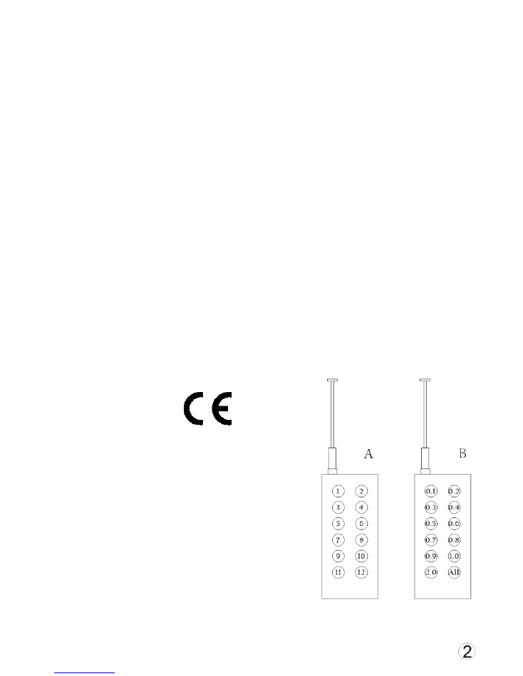
1)
Transmitters:
Transmitter A: Dividual Firing Transmitter. Buttons have 1,
2… 12. Each button fires its corresponding cue of the
firing module.
Transmitter B: Interval Firing Transmitter, Buttons have 0.1, 0.2 … 0.9, 1.0, 2.0, ALL. Fires 12 cues of
the firing module at 0.1s, 0.2s, 0.3s, … etc. separately.
Type: OOK, 433.92MHz.
Transmitting Range: 100-2000m.
Safety ON/OFF switch prevents
misfires.
2) Firing Module
Model No.: RF12A
Cue: 12 cues
Power: (Either internal or external)
Internal batteries: 6xAA battery,
rechargeable or disposable;
External Power: 6-20VDC, SLA is
recommended.
Firing current: >750mA, Max. 10A
Test current: <40mA
Size: 154mmx108mmx52.5mm,
antenna is retractile and foldable.
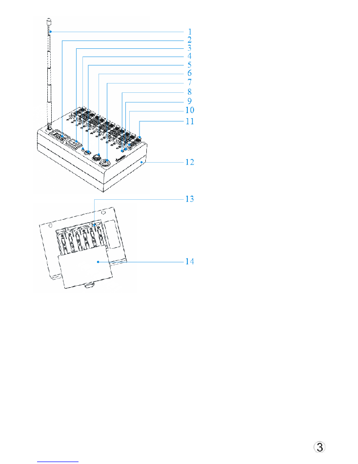
Parts
1- Telescopic Antenna
2- Digital Readout Meter
3- Rocker Switch, 3 positions Test / Learn /
Arm
4- Arm LED / Learn LED
5- Learn Button
6- External Battery Jack
7- Main Switch, lock switch
8- Cue Test LED, total 12 LEDs
9- Cue Fire LED, total 12 LEDs
10- Negative Terminals for cues
11- Positive Terminals for cues
12- Case
13- Battery Enclosure
14- Battery Cover
B. How the system works in Two Different Firing Modes
1) Use Transmitter A for Dividual Firing Mode
There are 12 cues (1-12) on the firing module and 12 fire buttons (1-12) on the transmitter. Press a fire
button on the transmitter to fire the same numbered cue on the firing module.
2) Use Transmitter B for Interval Firing Mode
The buttons are labeled 0.1-0.9, 1.0, 2.0, ALL. Press the desired interval (in sec.) that you want to have
between cues. Immediately, all cues will be fired in order 1-12, with the selected interval (in sec.) between
each cue. Push ALL to fire all cues at once.
C. Before Attaching E-matches/Igniters
1) Installing or Connecting Batteries
Internal batteries: Remove Battery Cover (#14) from battery enclosure. Insert 6xAA batteries into
Battery Enclosure (#13) and replace Battery Cover (#14).

External battery: Plug alligator clip wire into External Battery Jack (#6), and use red alligator clip to
connect the positive (red) terminal of the SLA battery, and black alligator clip to connect the negative (black)
terminal.
The firing module will work with either internal batteries or external powers. It will use the power with the
higher voltage.
2)
Safety Tests
Do following steps before attaching e-matches / igniters.
Step 1: Turn on the Main Switch (#7) and set Rocker Switch (#3) to Learn. If the battery voltage of
Digital Readout Meter (#2) is blank While there is LED(s) which is on, do not use this module,
because the battery voltage is too low to have the module work normally. Turn off the Main Switch (#7)
and remove internal or external batteries, replace with fully charged batteries or fresh batteries.
Step 2: If the firing module is not synchronized to the transmitters, perform “Learn Codes” on (see
“Learn Codes / Clear Codes” below) before performing the next step.
Step 3: Set Rocker Switch (#3) to Test. All Cue Fire LEDs (#9) and Cue Test LEDs (#8) should be
turned on. Any unlit cue is defective.
Step 4: Set Rocker Switch (#3) to Arm. All Cue Fire LEDs (#9) and Cue Test LEDs (#8) should be off.
If any Cue Fire LED (#9) stays lit, then that cue is defective.
Important:
Do not attach any e-match/igniter to defective cues under any circumstances, otherwise, that
e-match/igniter will fire prematurely. Premature ignition of fireworks can result in death or bodily harm.
Step 5: Set Rocker Switch (#3) to Arm. Extend the Antenna (#1). Press and release any Button 1 to 12
on transmitter A, the matching Cue Fire LED (#9) should flash on and off. Repeat this for different
buttons.
Step 6: Set Rocker Switch (#3) to Arm. Press and release any Button (except ALL) on transmitter B,
each Cue Fire LED (#9) should flash on and off in order using the selected interval. Push ALL and all Cue
Fire LEDs (#9) should flash on and off.
Step 7: Turn off Main Switch (#7). Retract Antenna (#1).
If the above safety tests are successful, you may attach lead wires of the igniters to the Negative
Terminal (#10) and Positive Terminal (#11).
D. Some Available Functions:
◆
◆
Learn Codes / Clear Codes
You must synchronize (learn) the A & B transmitters to one or more firing modules before they can
communicate. Extend the Antenna (#1). Turn on the Main Switch (#7) and set Rocker Switch (#3) to
Learn. Press Learn Button (#5) and hold until Learn LED (#4) is lit. Press any button on Transmitter
A within 5 seconds and, the Learn LED (#4) will blink twice, the learning is successful. Repeat the process
with Transmitter B.
Note: The firing module can store the learn codes from one A transmitter and one B transmitter only. If you
synchronize another A or B transmitter it will replace the learning of the previous A or B transmitter. You can
also synchronize the same transmitter to several firing modules, this allows you to fire the same cue on
each synchronized receiver at the same time.
To clear learning codes, press the Learn Button (#5) and hold for more than 10 seconds, the Learn LED
(#4) will light and blink three times, the codes are now cleared.
◆
◆
Test
You can test the continuity of any e-match/igniter that is connected to the cue terminals. Once all the
e-matches/igniters are connected, turn on the Main Switch (#7), set Rocker Switch (#3) to Test, if
Cue Test LED (#8) is lit and Cue Fire LED (#9) is unlit, that cue has continuity. Otherwise there is a bad
connection or a bad e-match/igniter.

◆
◆
Arm
Once the e-matches/igniters have been tested (previous paragraph), the firing module is ready to fire them.
Extend the Antenna (#1), turn on the Main Switch (#7) and set Rocker Switch (#3) to Arm, Arm
LED (#4) will be lit. Press a button on a “learned” (see “Learn Codes” above) transmitter to send a signal,
Cue Fire LED (#9) will flash, and the e-match/igniter on that cue will fire. See “B. How system works in
Two Different Firing Modes” for more details. When finished firing cues, turn off the Main Switch (#7)
and retract the Antenna (#1).
◆
Low Power Alarm
◆
The Digital Readout Meter (#2) will blink continuously when battery voltage is less than 6.5 volts, no
matter what Rocker Switch (#3) is set to. Now would be a good time to replace the batteries as they have
limited use. Turn off the Main Switch (#7) and remove internal or external batteries, replace with fully
charged batteries or fresh batteries.
◆
◆
Digital Readout Meter
Set Rocker Switch (#3) to Learn or Arm and the Digital Readout Meter (#2) shows the voltage of the
battery.
Manufacturer: RFRemotech
E-mail:
service@RFRemotech.com
Http://www.RFRemotech.com
June, 2015

N
OTE
:
This equipment has been tested and found to comply with the limits for a Class B digital
device, pursuant to part 15 of the FCC Rules. These limits are designed to provide reasonable protection
against harmful interference in a residential installation. This equipment generates, uses and can radiate
radio frequency energy and, if not installed and used in accordance with the instructions, may cause
harmful interference to radio communications. However, there is no guarantee that interference will not
occur in a particular installation. If this equipment does cause harmful interference to radio or television
reception, which can be determined by turning the equipment off and on, the user is encouraged to try to
correct the interference by one or more of the following measures:
—Reorient or relocate the receiving antenna.
—Increase the separation between the equipment and receiver.
—Connect the equipment into an outlet on a circuit different from that to which the receiver is
connected.
—Consult the dealer or an experienced radio/TV technician for help.
This
device
complies
with
part
15
of
the
FCC
rules.
Operation
is
subject
to
the
following
two
conditions:
(1)
this
device
may
not
cause
harmful
interference,
and
(2)
this
device
must
accept
any
interference
received,
including
interference
that
may
cause
undesired
operation.
Changes
or
modifications
to
this
unit
not
expressly
approved
by
the
party
responsible
for
compliance
could
void
the
user's
authority
to
operate
the
equipment.