Full Text Searchable PDF User Manual
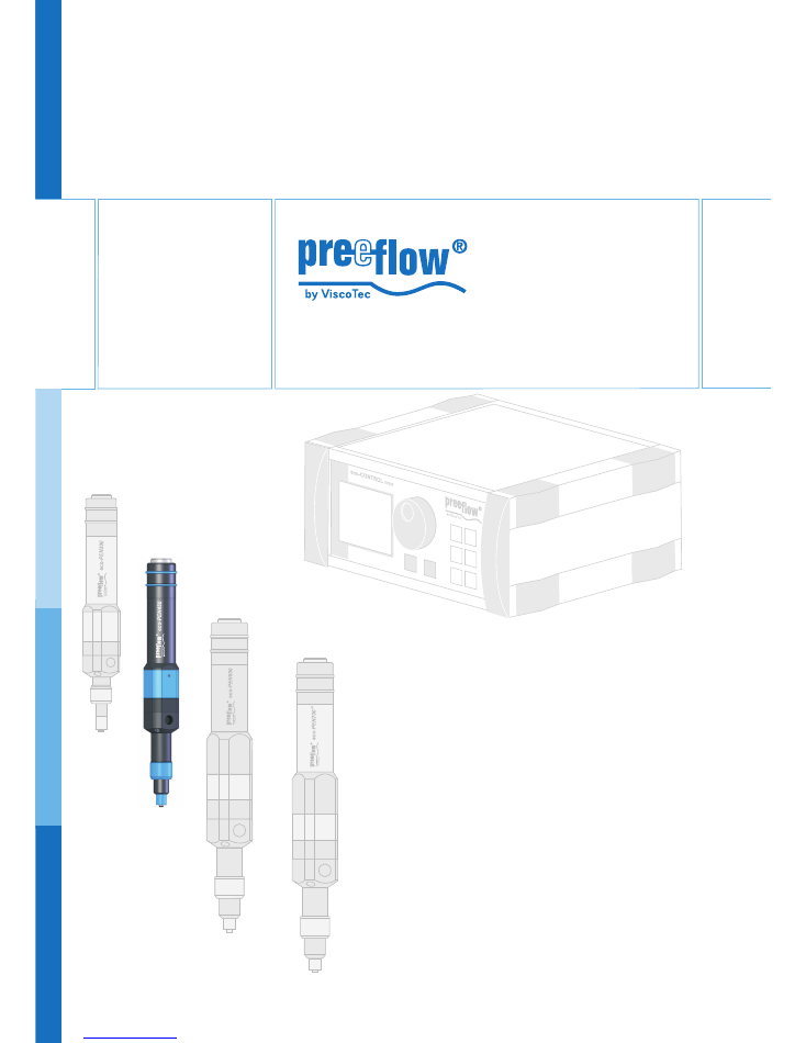
Dosing system
Commissioning and
maintenance manual
eco-PEN450


eco-PEN450
Commissioning and maintenance manual
Copyright ©
Version 1.8
3 / 15
Contents
1
This manual
5
2
The dispenser
5
3
Safety
5
4
Starting up for the first time
6
4.1 Inserting the stator
6
4.1.1 Connecting the dosing unit to the drive unit
7
4.1.2 Supply and bleed the medium.
7
5
Connection options
9
6
Cleaning
10
7
Spare parts
11
8
Maintenance
12
8.1 Changing the stator
12
8.2 Troubleshooting
12
9
Disposal
12
10
Technical specifications
13

eco-PEN450
Commissioning and maintenance manual
4 / 15
Version 1.8
Copyright ©
eco-PEN450
Commissioning and maintenance manual
Copyright ©
Version 1.8
5 / 15
1
This manual
Dear customer,
This manual forms part of the operating and maintenance manual for the dosing system
eco-CONTROL EC200. The operating and maintenance manual must have been read
and understood in full before commissioning or carrying out maintenance work on the
eco-PEN450.
2
The dispenser
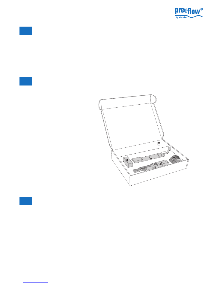
The dispenser is supplied with these components and accessories:
3
Safety
All instructions in the Safety section of the maintenance and operating manual for the
dosing system must be complied with and implemented.
fig. 1
A
Dosing unit
B
Stator
C
Drive unit
D
Assembly aid
E
Installation tool
(2 Allen wrenches)
F
Spraying device (without fig.)
eco-PEN450
Commissioning and maintenance manual
6 / 15
Version 1.8
Copyright ©
4
Starting up for the first time
4.1
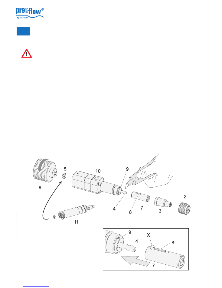
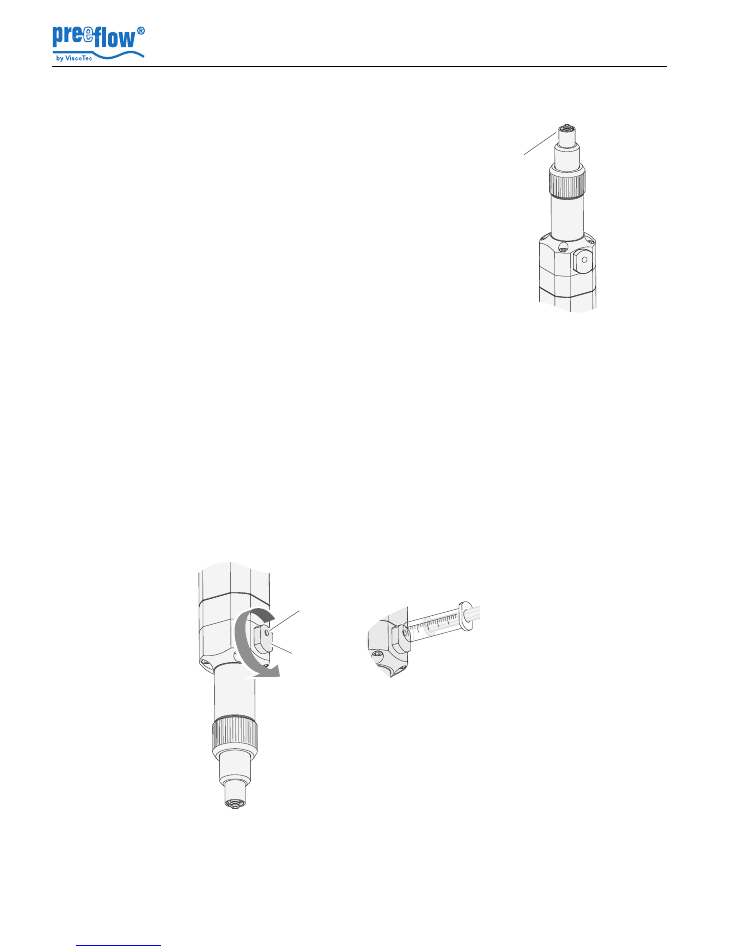
Inserting the stator
Preparation
: Unplug the power supply to the drive unit.
1. Undo the union ring (2).
2. Pull off the end piece (3).
3. Couple the assembly aid (6) to the dispenser housing (10)
(the star-shaped coupling (5) must be attached to the dispenser housing).
4. Wet the rotor (4) with the medium or a suitable lubricant.
5. Turn the stator (7) (on the bearing side, see Fig. A) on the rotor (4) until the dowel pin
begins to dip into the keyway (9).
6. Lightly press the stator in the direction of the dispenser housing (10) and turn the
assembly aid in the direction of the arrow until the stator has been guided into the
dispenser housing.
7. Uncouple the assembly aid, install the end piece and the union ring, and put in place
the required Luer-Lock needle.
Dispenser
Do not switch on
until medium has been delivered to it. Otherwise there is a
risk of
damage to the equipment. Even a brief period of dry running can lead to the
stator being destroyed.
Fig. A
Medium
fig. 2
eco-PEN450
Commissioning and maintenance manual
Copyright ©
Version 1.8
7 / 15
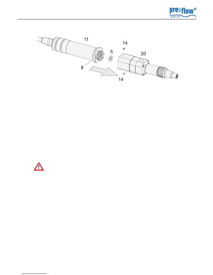
4.1.1 Connecting the dosing unit to the drive unit
1. Turn the set screws (14) in the thread such that they do not protrude into the coupling
area.
Danger of damage to the fit
.
2. Attach the star-shaped coupling (5) onto the coupling of the drive unit( 11).
3. Couple the drive unit (11) to the dosing unit (20) until there is a gap <1 mm between
the anti-rotation lock (8) and the dosing unit (20).
4. Set the anti-rotation lock (8) correctly in place by rotating the dosing unit (20).
5. Bring the drive unit (11) and the dosing (20) together completely.
6. Lightly turn the set screws (14), the drive unit (11) has now been centred properly.
4.1.2 Supply and bleed the medium.
• Connect the tank (supply line, cartridge) of the medium to the dispenser medium input
(12). (See section
10, Technical specifications,
, page
13
for details of the thread)
The Dispenser can be bled in one of two ways after the medium has been supplied.
Follow the safety stipulations and instructions of the manufacturer of the medium
to be used to fill the unit. If applicable, use the required protective equipment. If
the medium is being conveyed for the first time, there is a
danger
from
medium
spurting out
. Air bubbles can cause uncontrollable spurting out. Ensure that you stand
back a safe distance.
fig. 3
eco-PEN450
Commissioning and maintenance manual
8 / 15
Version 1.8
Copyright ©
Version B
(e.g. open cartridge, Dispenser fixed in place and supply of the medium under pressure)
• Turn the bleed screw (23) 180 degrees so that the bleed hole is in the position shown
(direction of the drive unit).
• wait until the medium emerges from the bleed hole free from air bubbles.
• Release (remove) the primary pressure on the medium and wait until no more medium
comes out of the bleed opening.
• Remove the ejected medium and close the bleed screw (23) again.
Connect the Dispenser to the power supply and convey the medium until there are no
more air bubbles in it and the outlet nozzle (with the Luer-Lock needle) comes out.
Alternatively, the air can also be extracted from the pump area with the syringe (9)
included in the scope of supply.
Version A
(e.g. supply via a hose, closed cartridge)
• Dispenser bring it into a position in which the end piece
(3) points upwards.
• Dispenser connect the unit to the power supply and
convey the medium until there are no more air bubbles
in it and the outlet nozzle (with the Luer-Lock needle)
comes out.
Tip
: Connecting a hose can protect the Dispenser from
being wetted with the medium.
3
fig. 4
23
8
9
fig. 5
eco-PEN450
Commissioning and maintenance manual
Copyright ©
Version 1.8
9 / 15
5
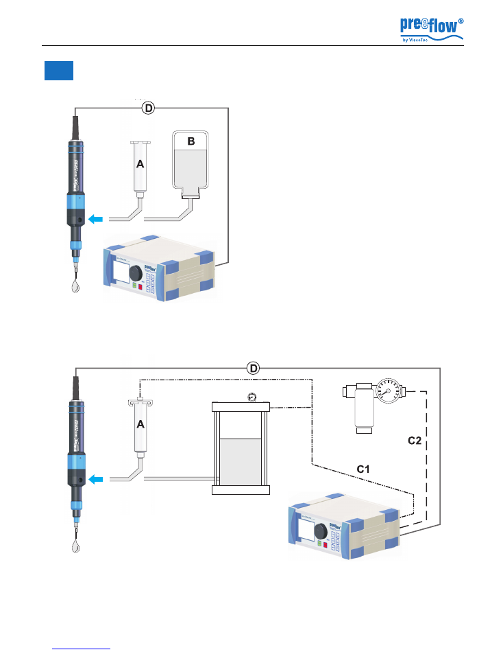
Connection options
Self-levelling liquid, low viscosity medium
Supply of the medium from a cartridge (A) or a
bottle (B).
D Power supply drive unit
Note
: Select the size of the hose to be such that
the liquid comes out by gravity and without any
air bubbles at the Dispenser.
Self-suction is possible.
Not a self-levelling liquid, medium/high viscosity medium
1. Cartridge (A) supplied with compressed air (C1), connected to the Dispenser.
2. Medium supply from the pressure tank (C).
fig. 6
C1
Compressed air, 0-6 bar,
regulated
C2
Compressed air, 7 bar, dry,
cleaned, oil-free
D
Power supply drive unit
fig. 7
eco-PEN450
Commissioning and maintenance manual
10 / 15
Version 1.8
Copyright ©
6
Cleaning
Preparation
:
Remove the dosing needle,
danger of injury!
Disconnect the power supply of the drive unit and uncouple it from the dosing unit (in the
reverse order to that described in
4.1.1, Connecting the dosing unit to the drive unit,
page
7
).
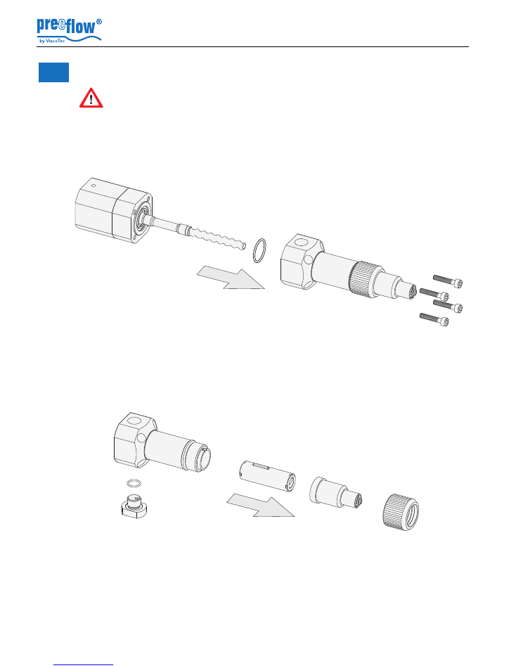
1. Undo the screws (18) and pull out the front dispenser housing (19) with the O-ring (22)
from the module (15) while turning it slightly.
2. Undo the union ring (2).
3. Pull off the end piece (3).
4. Pull the stator (7) out of the front dispenser housing (19).
5. Undo the bleed screw (23) and the washer (24).
6. Clean all the parts.
Assembly:
1. Attach the dispenser housing (19) with the O-ring (22) to the module (15) with the
screws (18) (do not exceed a tightening torque of 0.35 Nm).
2. Install the stator in accordance with work steps 4. to 7. described in section
4.1,
Inserting the stator,
page
6
.
3. Connect the dosing unit to the drive unit (see
4.1.1
, page
7
).
18
22
15
19
Note
: Do
not
rinse out the rotor
housing (15), because that could
damage the bearings! Clean it
with a cloth and brush.
fig. 8
23
24
3
2
19
7
fig. 9
eco-PEN450
Commissioning and maintenance manual
Copyright ©
Version 1.8
11 / 15
7
Spare parts
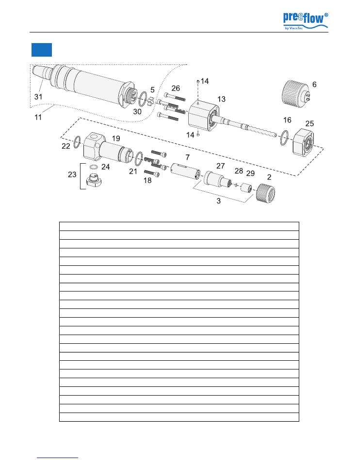
Item Part No. x Item name
Material
20091
Dosing unit eco-PEN450 cpl. (without 11)
2
20085
Union ring eco-PEN450
Aluminium
3
20075
End piece eco-PEN450 with Luer-Lock cpl.
POM
5
20050 x Star-shaped coupling
Elastomer
6
20108
Assembly aid
Aluminium
7
20001 x Stator cpl. eco-PEN450
VisChem
11
20081 x Drive unit eco-PEN450 cpl.
13
20149
Bearing housing with rotor set cpl.
14
20088
Set screw
A2
16
20007 x O-ring Ø 16
FKM
18
20089
Allen screw
A2
19
20083
Dispenser housing eco-PEN450
POM
21
20084 x O-ring Ø 15
FKM
22
20011 x O-ring Ø 13
FKM
23
20510
Bleed screw cpl.
POM
24
20513
O-ring
FKM
25
20148
Seal set with housing
26
20090
Allen screw
A2
27
20076
End piece eco-PEN450 with Luer-Lock
POM
28
20035 x O-ring
FKM
29
20021
Threaded sleeve Luer-Lock
Aluminium
30
20041 x O-ring Ø 17
NBR
31
20784
motor cable eco-PEN cpl.
x = recommended spare parts ad wearing parts
fig. 10
eco-PEN450
Commissioning and maintenance manual
12 / 15
Version 1.8
Copyright ©
8
Maintenance
8.1
Changing the stator
• Remove the defective stator (see section
6, Cleaning,
page
10
)
• Install the new stator (see "Assembly" in section
6, Cleaning,
page
10
)
8.2
Troubleshooting
9
Disposal
Error
Possible cause
Correction
No or too little
medium conveyed
Needle blocked
Clean / replace the needle
Medium hardened
Dispenser clean
Needle too small or too long
Use a different needle cross-
section. Reduce the speed / flow
rate.
Stator swollen
Replace the stator
Inadequate supply of medium
Supply the medium, check the
hose, check the primary pressure
and increase it if necessary.
Motor not connected
Connect the motor
Dripping / running on of the
medium
Sucking back not set correctly
Set the sucking back
Air bubbles in the medium
Bleed the medium
Medium compressible
Degas the medium
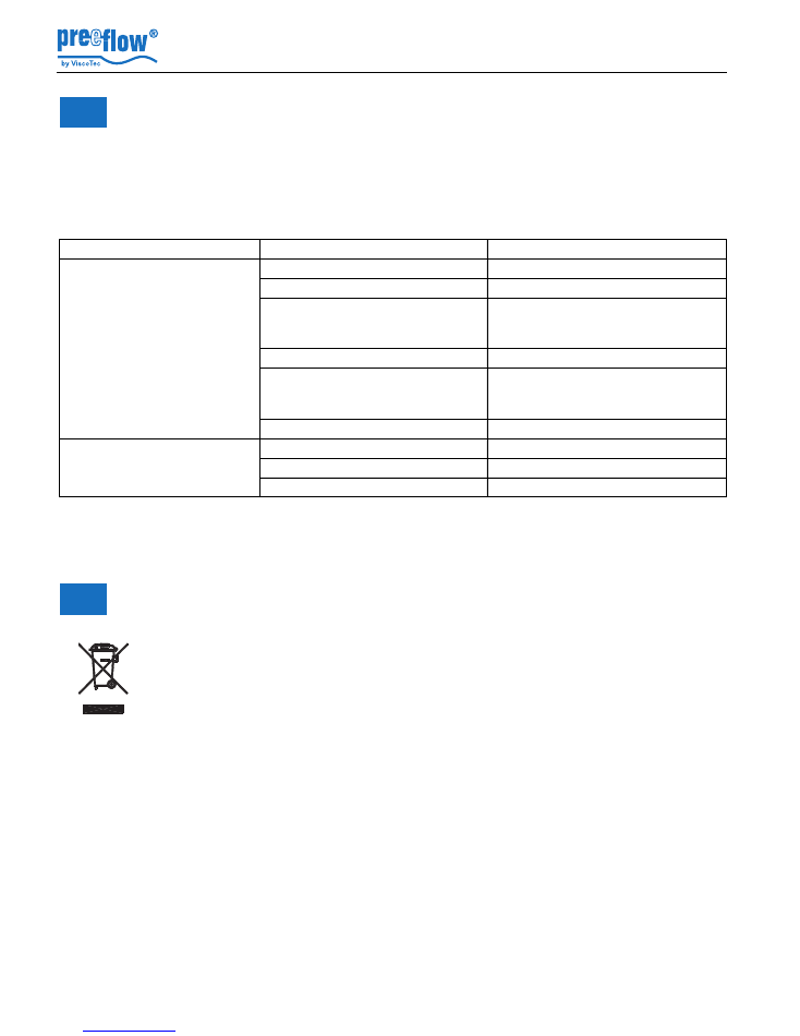
The final disposal of the Dispenser is to be done in an environmentally-appropriate
way. All the materials and packaging must be handled in accordance with the
recycling stipulations.
Do not dispose of electrical parts in the household garbage. They are to be taken
to the appropriate collecting points. 2002/96/EU(WEEE)* EU DIRECTIVE
concerning used electrical and electronic equipment
eco-PEN450
Commissioning and maintenance manual
Copyright ©
Version 1.8
13 / 15
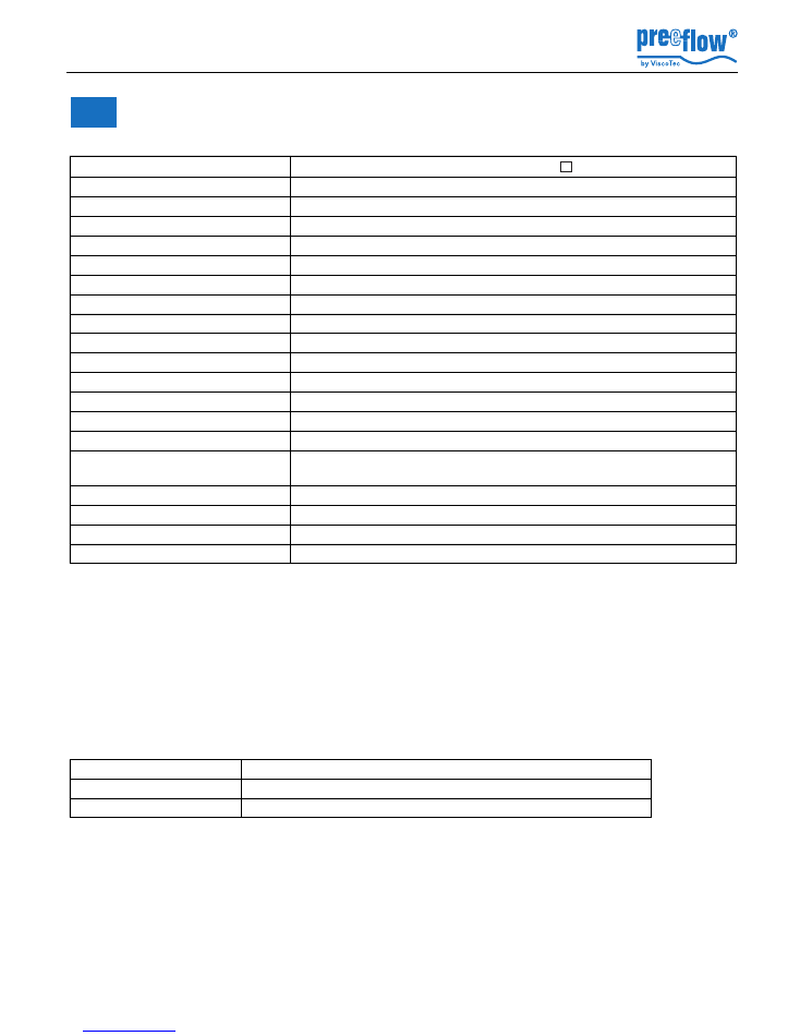
10
Technical specifications
Dimensions
Length 210 mm,
29 x 29 mm, ø 33 mm
Weight
approx. 410 gram
Material infeed
1/8“ cylindrical whitworth pipe thread DIN/ISO 228
Material outfeed
Luer lock with O ring, patented
Min. operating pressure
0 bar, self-levelling-fluid
Max. operating pressure
0 to 6 bar input pressure, non-self-levelling-fluid
Max. dosing pressure
16 to 20 bar
Intrinsic tightness *
approx. 2 bar (reference medium approx. 10mPas at 20°C)
Parts in contact with the media
HD-POM / stainless steel
Seals
High-molecular PE, VisChem
Static seals
Viton O ring (medium) NBR (dust)
Motor
18 - 24 V DC, incremental encoder, planetary gears
Operating conditions
+10°C to +40°C, air pressure 1 bar
Medium temperature
+10°C to +40°C
Storage environment
dry & dust-free, -10°C to +40°C
Approx. dosing volume per
revolution
0.05 millilitres per revolution
Accuracy of dosing **
± 1%
Repeat accuracy
> 99%
Min. dosing quantity
0.004 millilitres
Volume flow ***
0.5 to 6.0 millilitres per minute
* Max. dosing pressure and intrinsic tightness will decrease in direct proportion to a decrease in
viscosity and increase in direct proportion to an increase in viscosity. Consultation with the
manufacturer recommended.
** Volumetric dosing as absolute deviation in relation to one dispenser revolution. Depends on
the viscosity of the dosing medium.
*** Volume flow depends on viscosity and primary pressure.
Threads used
Medium input
1/8" cylindrical Whitworth pipe thread DIN / ISO 228
Bleed opening
Luer DIN EN 20594-1
Nozzle connection
LUER-LOCK DIN EN 1707 with O-ring, patented

eco-PEN450
Commissioning and maintenance manual
14 / 15
Version 1.8
Copyright ©
Materials used
Dispenserhousing, end
nozzles
POM black
Shaft sealing rings
Z80
Dispenserparts, motor housing Anodized
aluminium
O-rings
FKM
Screws, washers, etc.
Stainless steel A2
Drive shaft, rotor
Stainless steel A4
Stator elastomer, flexible shaft
covering
VisChem

eco-PEN450
Commissioning and maintenance manual
Copyright ©
Version 1.8
15 / 15
Notes
letzteSeite

info@preeflow.com
www.preeflow.com