Full Text Searchable PDF User Manual

ORIGINAL INSTRUCTIONS
USER MANUAL
Inverter welder PM-MMA-250SP /
PM-MMA-300S

1
Table of Contents
SYMBOLS WARNING / INFORMATION .............................................. ........................................... 2
APPLICATION EQUIPMENT ................................................ .................................................. ............... 2
TECHNICAL DATA ................................................ .................................................. ................................ 2
SAFETY ................................................. .................................................. ................................ 3
GENERAL THOUGHTS ................................................ .................................................. .................................... 3
Safety during welding ............................................... .................................................. 3 ....
Electromagnetic field ................................................ .................................................. .................. 5
Pacemakers ................................................ .................................................. ............................... 5
DESCRIPTION OF THE DEVICE ................................................ .................................................. ................................. 6
DESCRIPTION OF SYMBOLS ON THE LABEL ............................................. ....................................... 8
SIMPLIFIED INSTRUCTIONS FOR USE ............................................... ........................................... 8
INSRUKCJA INSTALLATION AND USE .............................................. .................................................. . 9
Place using the unit ............................................... .................................................. ........ 9
Current power and grounding. .................................................. .................................................. ............ 9
Welding service ................................................ .................................................. ............................ 10
Description welding process ............................................... .................................................. ..................... 10
One specific example of welding by means of electrodes. .................................................. ...................... 10
BASIC INFORMATION FOR WELDING .............................................. ........................... 11
FEATURE ARC FORCE ............................................... .................................................. ............................ 12
WELDING ELECTRODES IN PRACTICE .............................................. ................................................. 12
Electric arc welding ............................................... .................................................. ........ 13
Selection of appropriate electrode ............................................... .................................................. ........ 13
Correct welding position ............................................... .................................................. .......... 14
Tips arc ignition .............................................. .................................................. ..... 14
Proper arc length ............................................... .................................................. .................. 14
The correct welding speed ............................................... .................................................. ....... 15
Practice welding ................................................ .................................................. ........................... 15
Practical exercise ................................................ .................................................. ...................... 15
Base metals ................................................ .................................................. ...................... 16
PARAMETERS TABLE PADS ............................................... .................................................. ...... 17
MAINTENANCE AND SERVICE ............................................... .................................................. ...................... 17
REMOVAL OF USED ............................................... .................................................. ....... 18
COMPANY INFORMATION ................................................ .................................................. ............................ 18
DECLARATION OF CONFORMITY ................................................ .................................................. .................... 19
2
SYMBOLS WARNING / INFORMATION
APPLICATION EQUIPMENT
The device is used for welding any type of welding electrodes. The product to which this manual is electronically
controlled inverter welding machine MMA. Electronics devices based on the IGBTs combine the advantages of two
types of transistors FET ease of operation and high breakdown voltage and switching speed of bipolar transistors.
The device is versatile, such as performing field work and all kinds of repair work inside buildings.
Use the equipment only for its intended purpose. Any other use than described in this manual is the improper use of
the device. For resulting from improper use damage or injuries responsibility of the user / operator and not the
manufacturer. Producer in order to improve its products reserves the right to possibility of differences in the above
mentioned product.
TECHNICAL DATA
Model
PM-MMA-250SP
PM-MMA-300S
Power
230V / 50Hz
230V / 50Hz
Open circuit voltage
66v
66v
Welding current range
20-250
20-300
In the field of welding
electrodes
1.6 - 4.0 mm
1.6 - 4.0 mm
Power consumption
7,1kVA
7,6kVA
Power
230V / 50Hz
230V / 50Hz
Rated welding current
250A
300A
Rated duty cycle
60%
60%
Welding current at duty cycle of
100%
193A
216A
WARNING:
Before using the device please read the instruction manual and safety instructions.
WARNING:
Before using the device please read the instruction manual and safety instructions.
Keep these instructions.
WARNING:
Keep a safe distance from bystanders during operation.
WARNING:
Keep a safe distance from bystanders during operation.
WARNING:
To protect the unit from rain and moisture.
WARNING:
To protect the unit from rain and moisture.
3
operating voltage
20,8- 30V
20,8- 30V
Protection class
F
F
insulation class
IP21S
IP21S
Weight
6,8kg
7,9kg
SECURITY
Before starting work carefully to become familiar with the manual. Keep them for future reference. For damages
resulting from failure to observe these instructions, the manufacturer is not liable.
The greatest danger is prohibited to perform the following steps:
and) Welders use for purposes other than those described in the manual.
and) Welders use for purposes other than those described in the manual.
b) Using a welder by people niezapoznane manual.
b) Using a welder by people niezapoznane manual.
c) Using welders without proper, protective clothing and footwear that supports
c) Using welders without proper, protective clothing and footwear that supports
protecting the foot.
d) The use of the device by a person under the influence of alcohol, drugs or other substances
d) The use of the device by a person under the influence of alcohol, drugs or other substances
drugs. And also by persons with reduced physical, sensory or mental capabilities, or lacking experience or
knowledge concerning the use of this type of equipment.
GENERAL THOUGHTS
Safety during welding
ELECTRIC SHOCK CAN KILL:
Welding apparatus produce a high voltage. Do not touch the torch,
ELECTRIC SHOCK CAN KILL:
Welding apparatus produce a high voltage. Do not touch the torch,
welding material connected when the device is turned on to the network. All the elements forming
the welding current circuit can cause electrical shock and should therefore be avoided
touching them with bare hands and by wet or damaged protective clothing. Never work on a wet surface, or use
damaged welding cables. NOTE: Removing the external time when the device is connected to the network, as well as
the use of the device with the covers removed is prohibited! Welding cables, ground cable, earthing terminal and
welding equipment should be kept in good condition, ensuring safety.
ARC RAYS CAN BURN:
It is not allowed to look directly at the eyes uncovered and exposed to an
ARC RAYS CAN BURN:
It is not allowed to look directly at the eyes uncovered and exposed to an
electric arc. Always wear a mask or helmets protected with a suitable filter. Bystanders, nearby,
protected with non-combustible, absorbing radiation screens. Protect
exposed parts of the body suitable protective clothing made of non-combustible material.
FUMES AND GASES CAN BE DANGEROUS:
In the welding process are produced noxious fumes
FUMES AND GASES CAN BE DANGEROUS:
In the welding process are produced noxious fumes
and gases hazardous to health. Avoid breathing these fumes and gases. Workplace should be
adequately ventilated and equipped with exhaust ventilation. Do not weld in confined spaces.
surfaces
the elements to be welded should be free from chemical impurities such
4
as degreasing agents (solvents) which decompose during welding to produce toxic gases.
ELECTROMAGNETIC FIELDS MAY BE DANGEROUS:
Electric current flowing through wires
ELECTROMAGNETIC FIELDS MAY BE DANGEROUS:
Electric current flowing through wires
Welding produces electromagnetic field around it. Electromagnetic fields can interfere with
pacemakers. Welding cables should be arranged in parallel, as close as possible to each other.
SPARKS CAN CAUSE FIRE:
Sparks generated during welding can cause fire, explosion and burns
SPARKS CAN CAUSE FIRE:
Sparks generated during welding can cause fire, explosion and burns
unprotected skin. When welding should be wearing welding gloves and protective clothing. Remove
or secure any flammable materials and substances from the workplace. Do not weld
closed containers or receptacles in which there were flammable liquids. Such containers or tanks should be rinsed
prior to welding in order to remove flammable liquid. Do not weld near flammable gases, vapors or liquids. Fire
extinguishing equipment (fire blankets and fire extinguishers powder or snow) should be located close to the
workstation in a conspicuous and easily accessible place.
POWER SUPPLY:
Disconnect the power supply before carrying out any work, repairs on the device.
POWER SUPPLY:
Disconnect the power supply before carrying out any work, repairs on the device.
Regularly check the welding cables. If you note any damage to the wire or insulation should be
removed immediately. Welding wires can not be overwhelmed,
touch sharp edges or hot objects.
WELDED MATERIALS CAN BURN:
Never touch the parts to be welded unprotected parts of the
WELDED MATERIALS CAN BURN:
Never touch the parts to be welded unprotected parts of the
body. While touching and moving the welding material, always use gloves and welding pliers.
Noise can damage hearing:
Noise-induced, some processes
Noise can damage hearing:
Noise-induced, some processes
or
devices can damage hearing. Wear hearing protection in situations of increased noise levels.
FIRE OR EXPLOSION:
Do not use the machine near flammable substances. Make sure that the
FIRE OR EXPLOSION:
Do not use the machine near flammable substances. Make sure that the
electrical network is properly configured to work with the welder. Overloading the power supply may
cause fire.
FALLING EQUIPMENT CAN BE DANGEROUS:
To move the machine, use the handle of transport.
FALLING EQUIPMENT CAN BE DANGEROUS:
To move the machine, use the handle of transport.
All the equipment necessary to lift the unit must have sufficient capacity and stable hook. When
moving the machine by forklift truck, the forks must be long enough to protrude beyond the device.
5
Overload can cause overheating:
Do not extend the cycle of welding, welding between cycles allow
Overload can cause overheating:
Do not extend the cycle of welding, welding between cycles allow
the device to cool. In the case of excessive heating of the device, shorten the cycle time of welding or
reduce the welding current.
STATIC DISCHARGE MAY DAMAGE THE PRINTED CIRCUIT:
Before touching the printed circuit
STATIC DISCHARGE MAY DAMAGE THE PRINTED CIRCUIT:
Before touching the printed circuit
boards and parts of the electrical system should be assumed grounding wrist-strap. Use of antistatic
packaging is storing and transporting electrical components.
READ INSTRUCTIONS:
Carefully read the manual and follow the information contained therein. For
READ INSTRUCTIONS:
Carefully read the manual and follow the information contained therein. For
any damage caused by failure to comply with the guidelines of this manual manufacturer is not
liable.
HIGH RADIATION
FREQUENCY:
high radiation
frequency radio signal can zakłucać, alarm systems, work computers and communications
equipment. User is obliged to ensure a qualified electrician correct the problems resulting from
zakłucenia electrical installation. Regularly check and maintain electrical installations. Use
grounding, shielding and anti-surge protection measures to minimize any zakłucenia.
ARC WELDING CAN CAUSE ZAKŁUCENIA:
Electromagnetic energy can interfere with electronic
ARC WELDING CAN CAUSE ZAKŁUCENIA:
Electromagnetic energy can interfere with electronic
equipment such as computers and computer-controlled equipment. Make sure that the hardware
devices in the work environment welders are electromagnetically compatible. To minimize the
potential for interference stick welding wires close to each other, as close to the ground. IN
If electrical noise sensitive spot welding should not be closer than 100m. The device must be connected and
grounded in accordance with this instruction. If noise still persists the user needs to take additional measures such as
changing jobs, the use of shielded cables, filters, linear and securing jobs.
Electromagnetic field
To reduce the amount of electromagnetic fields in the workplace include:
1. Keep cables close together (you can turn the tape or taped).
1. Keep cables close together (you can turn the tape or taped).
2. Organize the wires from one side of the operator as far as possible from him.
2. Organize the wires from one side of the operator as far as possible from him.
3. Do not wrap the cables around the body.
3. Do not wrap the cables around the body.
4. The power source and wires should be as far away from the operator as possible.
4. The power source and wires should be as far away from the operator as possible.
5. Connect the terminal welding seam as close as possible.
5. Connect the terminal welding seam as close as possible.
pacemakers
You should consult your doctor before welding and welding being in place. The doctor will explain the procedure if
any of the contact with the welding apparatus.
6
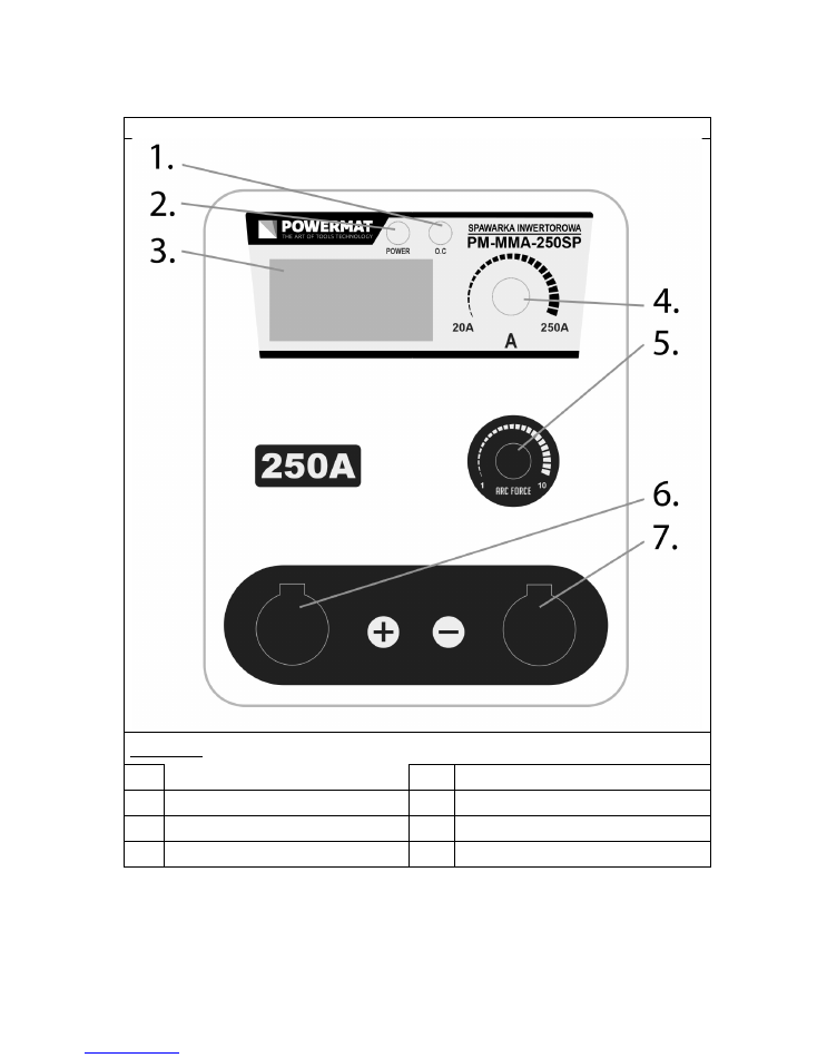
DESCRIPTION OF THE DEVICE
Model: PM-MMA-250SP
DESCRIPTION ELEMENTS
DESCRIPTION ELEMENTS
1.
LED indicating overload
5.
Knob Arc Force
2.
power LED
6.
The welding cable "+"
3.
Current meter
7.
Earth wire "-"
4.
potentiometer amperage
7
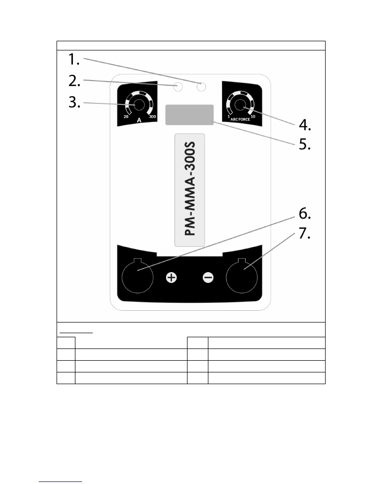
Model: PM-MMA-300SP
DESCRIPTION ELEMENTS
DESCRIPTION ELEMENTS
1.
power LED
5.
Current meter
2.
LED indicating overload
6.
The welding cable "+"
3.
potentiometer amperage
7.
Earth wire "-"
4.
Arc Force potentiometer
8
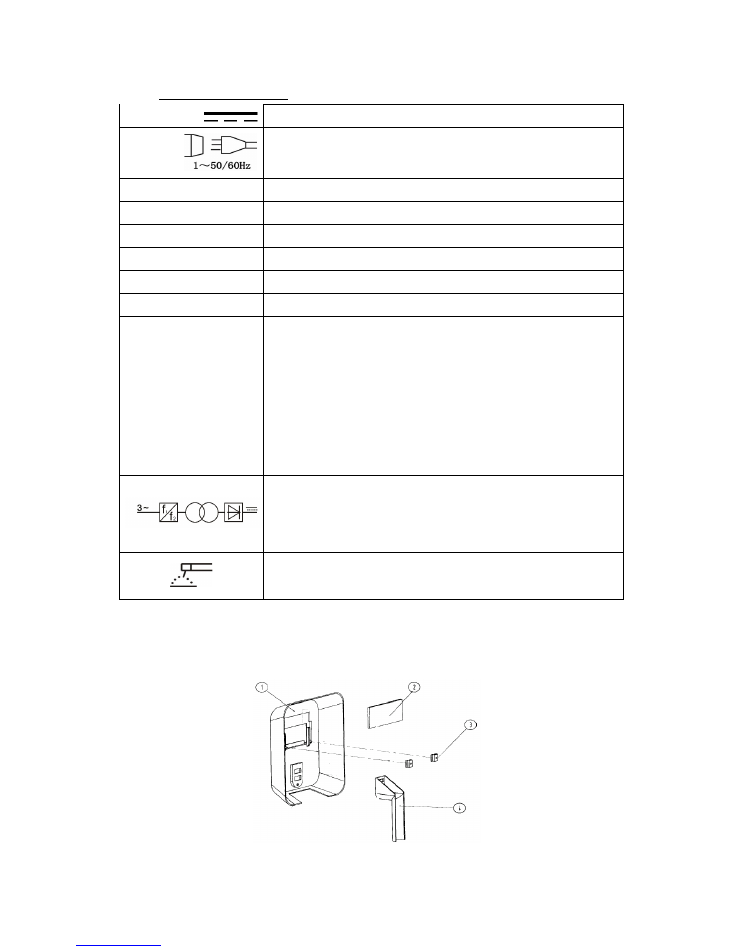
ABOUT MARKING THE PIS LABEL
ABOUT MARKING THE PIS LABEL
ABOUT MARKING THE PIS LABEL
Current (DC)
Symbol
single phase alternating current (AC) of the rated frequency 50Hz
and 60Hz operating frequency.
AT
1
Nominal input voltage (AC)
AT
1
Nominal input voltage (AC)
AT
1
Nominal input voltage (AC)
AND
1max
Maximum input current
AND
1max
Maximum input current
AND
1max
Maximum input current
AND
1EFF
Effective input current
AND
1EFF
Effective input current
AND
1EFF
Effective input current
AT
0
No-load voltage (load voltage)
AT
0
No-load voltage (load voltage)
AT
0
No-load voltage (load voltage)
AND
2
output current
AND
2
output current
AND
2
output current
AT
2
The output voltage under load
AT
2
The output voltage under load
AT
2
The output voltage under load
X
welding cycle
(This percentage ratio of working time under load to full duty cycle)
•
The value of 0-100%
• Standard for this device, one full cycle is 10 min. For example, 40% of the
cycle allows for continuous welding under load for 4 minutes. and the time
to "rest" should last 6 minutes. When the time under load the machine is
switched off by the thermal fuse.
The device welded single-phase DC
Welder is used for MMA welding
SIMPLIFIED INSTRUCTIONS FOR USE
Assembly welding mask
Welding mask assembly is performed according to the diagram.

9
1. Connect to the power welder, dial located at the rear of the unit.
1. Connect to the power welder, dial located at the rear of the unit.
2. Connect the ground wire to the quick and the workpiece.
2. Connect the ground wire to the quick and the workpiece.
3. Mount the electrode in the torch, and then connect the wire from the quick coupling.
3. Mount the electrode in the torch, and then connect the wire from the quick coupling.
4. Switch to the ON position and make sure the power LED indicator lights up
4. Switch to the ON position and make sure the power LED indicator lights up
yellow.
5. You can start the process of welding.
5. You can start the process of welding.
6. After welding is complete, move the electrode from the work piece and set
6. After welding is complete, move the electrode from the work piece and set
OFF switch in the OFF position.
Warning!
At the time of exceeding the cycle provided for the amperage thermal circuit breaker lock the device
Warning!
At the time of exceeding the cycle provided for the amperage thermal circuit breaker lock the device
(indicated by yellow LED Overload) until cool welding.
If your machine or its accessories will begin to work properly you should refrain from further work and contact a
qualified service center.
INSRUKCJA INSTALLATION AND USE
Installation of equipment
Only qualified personnel are allowed to install, use and service the welding machine.
Place of use of the device
The device can be used only in well-ventilated place.
Before working at the site of use should always take into account the guidelines for safety contained in the section
"GENERAL"
Welding cables must be connected to the output of the welding power source to the welding machine. Welder power cord
must be connected to a 230V AC power source.
Current power and grounding.
Only qualified personnel may perform installation and modification of the electricity grid.
Warning!
It is forbidden to use the device or completely dismantled the housing removed, it may cause electric shock
Warning!
It is forbidden to use the device or completely dismantled the housing removed, it may cause electric shock
and lead to severe injury. Do not touch the energized equipment.
Before installing the unit, check electrical network to which the device is connected meets the requirements placed on
the nameplate and that it meets all local and national standards. Keep in mind that different models of welding
machines may have different requirements for the electricity grid.
1. Before connecting check whether the network meets the requirements of the welding machine.
1. Before connecting check whether the network meets the requirements of the welding machine.
2. Connect the PE or green / yellow ground wire to the grounding system in accordance with the
2. Connect the PE or green / yellow ground wire to the grounding system in accordance with the
national regulations.
3. Connect the welding cables to the device, then the power cord to a single-phase network
3. Connect the welding cables to the device, then the power cord to a single-phase network
the electric voltage of 230V and frequency of 50Hz.
10
welding service
Welding current control is performed using the knob located on the top panel welder. Turning the knob (2)
right
welding
Welding current control is performed using the knob located on the top panel welder. Turning the knob (2)
right
welding
Welding current control is performed using the knob located on the top panel welder. Turning the knob (2)
right
welding
current increases, while traffic
left
current increases, while traffic
left
reduces welding current.
The current value of the welding current expressed in Amperes and presented on the display (1) located on the front
panel of the welder.
Description of the welding process
WARNING! The arc starts at the moment when the welding electrode to the welding point touch and then will
be moved to a distance the length of the arc.
One specific example of welding by means of electrodes.

11
BASIC INFORMATION FOR WELDING
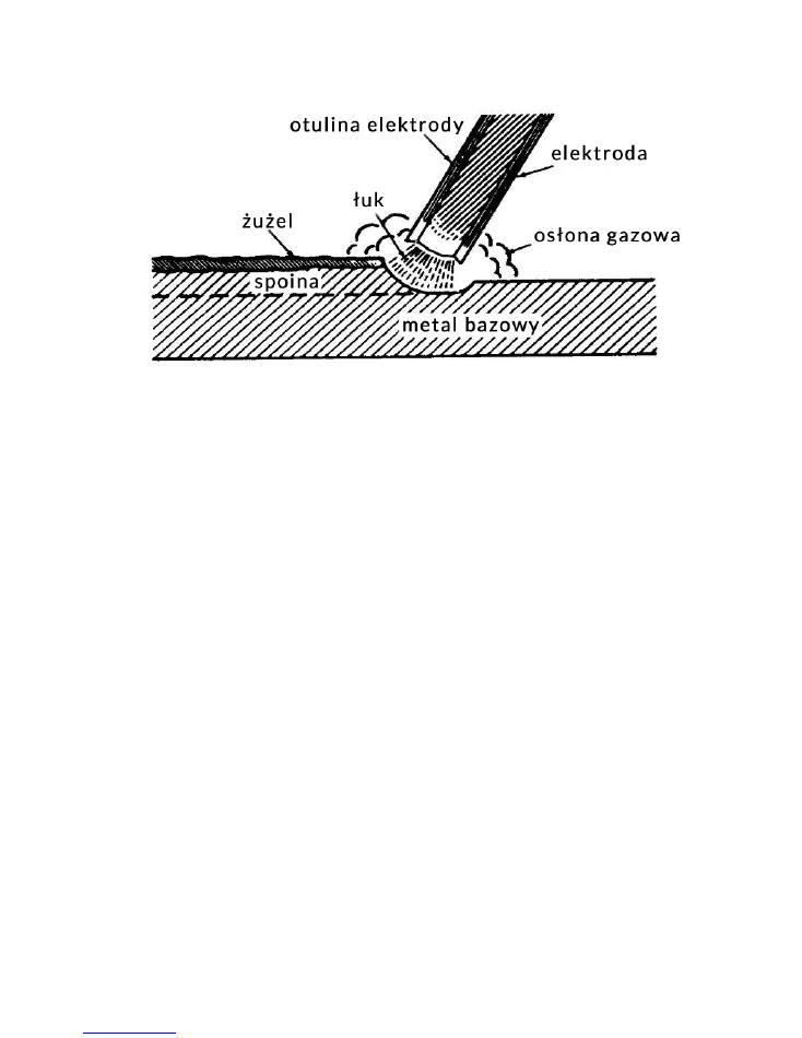
Otulinowymi welding electrodes (MMA) is a process in which metal is melted, and then combined, by heating it by
means of electric arc with consumable electrode coated metal wrapper flux. The electric current generates an electric
arc between the electrode and the material combined. During the welding electrode coating decomposes under heat
to form the gaseous substances which shield gas during the welding and slag.
If the electrode moves along a weld spot at the right speed deposited metal forms a layer called the seam.
Welding is powered by an AC source and can generate alternating current and constant. The best characteristics of the weld
obtained using a constant current.
In the circuit welding measured voltage and current. Voltage (V) is controlled by the arc length between the electrode and
welded surface and depends on the diameter of the electrode. It is a measure of the current in the welding circuit, and is
measured in amperes (A), is controlled by the dial. Setting the welding current is dependent on the diameter of the electrode
size and thickness of the welded material and the welding position. When welding materials with the same thickness,
materials with a small area is used lower electrode and a lower welding current than the larger
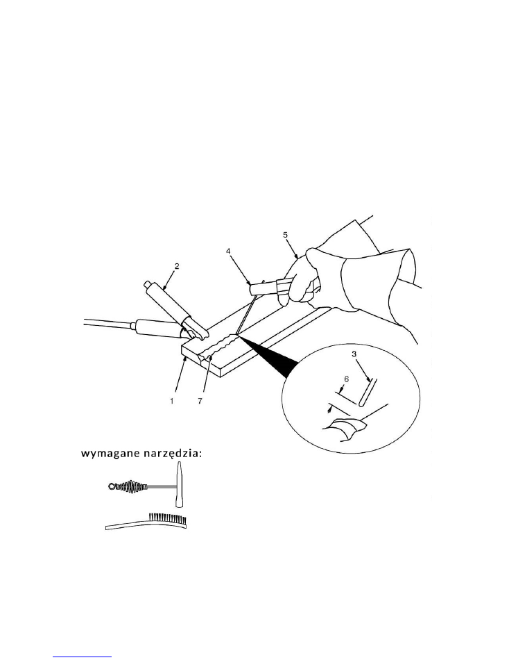
1.
Workplace
1.
Workplace
Make sure the work area is clean.
2.
earth wire
2.
earth wire
Clip the ground cable as close to the surface of the weld.
3.
Electrode
3.
Electrode
Before the electric arc ignition, place the electrode in the torch. With the electrodes of smaller diameter
to be operated at less than the current to the electrodes with a larger diameter. Follow the data on the
welding current provided by the manufacturer.
4.
Insulated welding gun.
5.
The correct position of holding the torch.
5.
The correct position of holding the torch.
6.
The length of the arc.
6.
The length of the arc.
The length of arc is the distance from the point of welding electrodes. In the case of a short arc of the
proper amperage and you hear sharp cracks. The appropriate length of the electric arc is similar to the
electrode diameter. Check the weld seam to determine if the arc is correct.
The length of the arc electrodes having a diameter of 1.6 mm and 2.4 mm should be greater than 1.6 mm, and the
electrodes 3mm and 4mm arc length should be greater than 3mm.
7.
Slag
7.
Slag
For removal of welding slag, use a hammer and brush. Remove slag and check weld bead before starting
a new weld.

12
surface. Thin metal requires less power, and smaller electrode requires less power.
It is recommended that during welding work in the horizontal and vertical positions. However, while we are forced to
weld in vertical or overhead should set the current lower than the level during operation. The best welds are obtained
while maintaining a short arc, smooth movement of the electrode and the electrode leading down at a constant speed
during melting. More detailed welding procedures are presented in the following pages Supported.
FEATURE ARC FORCE
ARC FORCE allows the arc. Shortening the length of the arc is accompanied by an increase in the welding current, which
results in stabilizing the arc. Reducing the value of the function gives a soft arc and a smaller depth of penetration, while
increasing the value of the function causes deeper penetration and the possibility of short-arc welding. At a set high value
ARC FORCE function you can be welded while maintaining the minimum arc length and a high melting rate of the electrode.
WELDING ELECTRODES IN PRACTICE
No one can learn to weld by reading the instruction manual or other literature on the subject. The ability to correct
welding can be purchased only through practice. The information contained in the attached manual to help you
understand those rules inexperienced welding with coated electrodes and make it easier to start learning. For more
information about welding can reach for a comprehensive literature deeply about.
Knowledge welding operator must go beyond information about the arc. User welders must know how to control the
arc, which requires knowledge of the circuit and the welding device that provides current during welding. The welding
cable starts in the torch, wherein the electrode is mounted, and the end on the connector, wherein the cable is
attached to the welding machine. Current flows through the wire to the welding electrode holder and then by the
electric arc. On the other side of the working arc current flows through the wire to the base metal mass, then back to
the device. The system must be closed. Mass holder to be stably mounted on the metal base cleared. Metal must be
cleaned of paint, rust, etc. It is necessary to obtain a good current flow. Connect the ground cable as close as
possible to the welding point. Avoid closing the circuit through the welding hinges, bearings, electrical systems and
other such items that may impede the flow of current in the system. The electric arc is formed in a space between the
work piece and the welding electrode tip mounted on the torch. The molten metal moves along the arc for the
combination of materials, forming a weld bond.
Electrode Welding requires a strong grip and a welding tip, stable hands, good vision and good mental health. The
operator controls the welding arc welding and thus, the quality of the weld created.
13
Electric arc welding
Fig. 1
Figure 1.
Presents phenomena occurring during arc welding, which is greatly enlarged what is seen by the welder.
Figure 1.
Presents phenomena occurring during arc welding, which is greatly enlarged what is seen by the welder.
Curved space is shown in a central position in the picture. Arc formed at a location between the electrode tip and the
base material. The arc welding reaches 3315
about
C, which is sufficient to melt the base metal. Since the arc is very
base material. The arc welding reaches 3315
about
C, which is sufficient to melt the base metal. Since the arc is very
base material. The arc welding reaches 3315
about
C, which is sufficient to melt the base metal. Since the arc is very
bright you can not look at him bare eyes, it can cause very painful burns of the retina or permanent eye damage.
They are designed for welding specialist welding masks and helmets protect the eyes during welding.
When working with an electric arc welder begins to "pull" handle, which is comparable to a stream of water from a
garden hose for use at the ground. The molten metal forms a lake or crater (small
area of the molten metal surface)
garden hose for use at the ground. The molten metal forms a lake or crater (small
area of the molten metal surface)
which follow for the electric arc. During the movement of the electrode puddle is cooled and solidifies. Slag emitted
during welding protects the weld during welding.
Selection of a respective electrode
The function of the covered electrodes is not only the transfer of power to the electric arc. The electrode is
constructed of a metal core and a cover. The metal core is melted in an electric arc to fill the gap between the two
pieces of combined metal. Lagging also melts or burns in an electric arc playing the same important functions in the
welding process. During the melting of the electrode decompose chemical compounds contained in the electrode
coating to form gaseous products, which stabilizes the electric arc cloud protects the molten metal from oxidation and
pollution in the atmosphere. Other chemicals get together with the molten metal from the core of the electrode to the
weld pool to form a slag that forms on the weld layer protecting from further oxidation during cooling.
The differences for the different types of electrodes refer mainly to the type of the buffer zone. Changing the outer coating
significantly affects the characteristics of welding. By understanding the differences in the types of buffer zones to gain
knowledge select the right electrode for the job.
14
When choosing the electrodes need to consider:
1. Implementation example. Steel, mild steel and stainless steel.
1. Implementation example. Steel, mild steel and stainless steel.
2. The thickness of the welded material.
2. The thickness of the welded material.
3. Position in which the weld is made.
3. Position in which the weld is made.
4. Technical state of the base metal.
4. Technical state of the base metal.
5. Own skills on using a welder.
5. Own skills on using a welder.
The first four points are necessary for the proper use of the welder without mastering their work will be hard and
tedious.
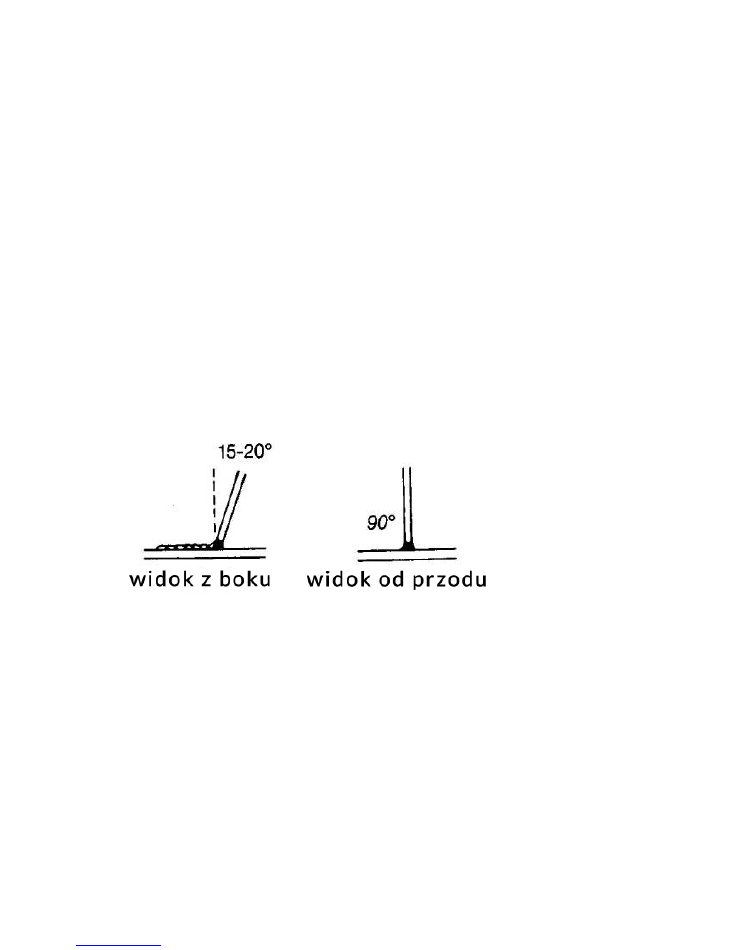
Correct welding position
The welding position presented is described for right-handed, in the case of left-handers will look exactly the opposite.
1. Catch the welding gun with his right hand.
1. Catch the welding gun with his right hand.
2. Put your left hand under your right hand.
2. Put your left hand under your right hand.
3. Put your left elbow to the left side of the body. If
3. Put your left elbow to the left side of the body. If
you can weld with both hands.
This will better control electrode.
Try to weld from left to right (if you're right-handed). You will see more precisely the welding area.
Fig. 2
Keep the electrode at a slight angle as shown in the figure.
Tips arc ignition
Make
out
that handle mass has good contact with the weld workspace.
Lower welding helmet and rub against metal electrode welding in place until you see sparks. While rubbing lift the
electrode at about 3mm to stabilize the arc.
Warning!
If you stop electrode while rubbing stick electrode.
Warning!
If you stop electrode while rubbing stick electrode.
Warning!
Most beginners trying to foment arc welders by tapping the electrode plate. As a result, the electrode or
Warning!
Most beginners trying to foment arc welders by tapping the electrode plate. As a result, the electrode or
sticks or the traffic is too fast and the arc is interrupted.
Proper arc length
Arc length is the distance from the end of the electrode to the workpiece. Once the arc is stabilized setting proper arc
length is very important. Arc should have
15
a length of approximately 1.5 - 3 mm. Due to the burning of the electrodes must be kept adjust the length of the arc.
Most simpler method of controlling arc is relying on its own hearing. The correct length of the arc is characterized by a
crackling sound like frying eggs patelce. Invalid too long arc is revealed empty hissing sound or a sound like blowing.
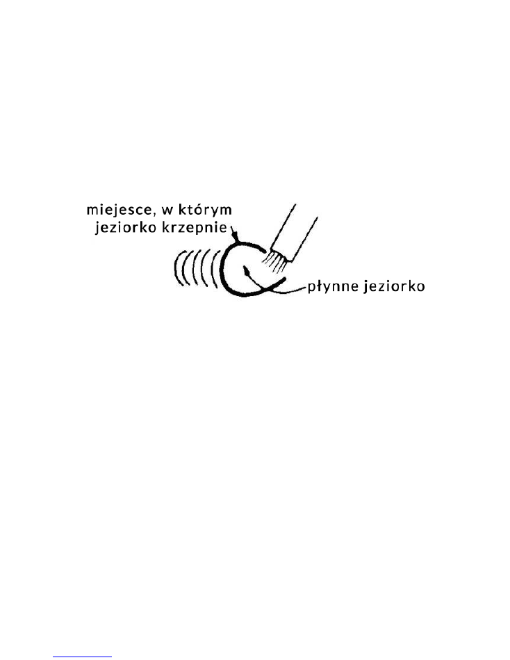
The correct welding speed
The important thing is to check whether the lake follows the arc.
Important can not look directly at the arc.
The
The important thing is to check whether the lake follows the arc.
Important can not look directly at the arc.
The
The important thing is to check whether the lake follows the arc.
Important can not look directly at the arc.
The
appearance of the weld puddle and back out of the solidification of the molten pool indicates a normal welding speed. The
appearance of the weld puddle and back out of the solidification of the molten pool indicates a normal welding speed. The
back surface should be formed about 10mm behind the electrode.
Fig. 3
Most people beginners tend to weld too fast, resulting in the effect of thin, similar to the "worm" thickening. This
happens when you do not observe the lake. Important. Welding is not necessary heave arc (side to side or front to
back). Weld a straight line at constant speed. It will be easier this way.
When the welding material of low thickness increase the speed of the electrode so as not to burn metal analogy
welding speed heavy materials should be smaller to increase the penetration of the weld.
practice welding
The best way to gain the skills of welding is practical exercise. During the exercise, remember to:
1. Proper welding position.
1. Proper welding position.
2. The proper way arcing arc.
2. The proper way arcing arc.
3. The correct length of the arc.
3. The correct length of the arc.
4. The correct speed.
4. The correct speed.
practical exercise
Will be needed:
1. Mild steel sheet: 5mm or thicker
1. Mild steel sheet: 5mm or thicker
2. electrode 3.2mm
2. electrode 3.2mm
3. Recommended setting: 100-120
3. Recommended setting: 100-120

16
and) Learn how to kindle a bow by rubbing on metal electrodes. Make sure that the angle of the electrode
and) Learn how to kindle a bow by rubbing on metal electrodes. Make sure that the angle of the electrode
It is correct and that you are using both hands.
b) When you learn to kindle practice a proper arc setting arc length using
b) When you learn to kindle practice a proper arc setting arc length using
sound that seems arc.
c) Once you have mastered this step, go to the proper welding. Watch and smooth lake
c) Once you have mastered this step, go to the proper welding. Watch and smooth lake
Search ridge, the place where the metal solidifies.
d) Do stitches on a flat metal surface. Do them in parallel to the upper edge (the edge
d) Do stitches on a flat metal surface. Do them in parallel to the upper edge (the edge
furthest from you). This will give you practical skills in running straight welds, and also allow you to
easily track your progress. You will notice that the tenth weld will look much better than the first. By
constantly checking their mistakes and correct them, your progress in welding technology will keep the
increase. Through regular exercise after some time welding will be a matter of routine.
Base metals
Most metals found in farms and small shops are low carbon steel, sometimes offered mild steel. Typical items made
with this type of steel is the most common metal plates, pipes, rolling, angles, beams. This type of steel can usually
pospawać without special precautions. However, some types of steel contain large amounts of carbon. Such steels
are most commonly used in the connecting rods, knives and cutting grinding, axles, shafts, plowshares. Carbon steels
in most cases can be welded with success, however, caution should be exercised in maintaining proper temperatures
in the earlier welding and reheating the material to be welded. In some cases, you must carefully control the
temperature during the welding and the welding process. For comprehensive information on identifying and welding
different types of steel and other metals we purchase and read the detailed literature devoted to welding. Regardless
of the type of material to be welded, it is important to clean it of any dirt (rust, paint, oil, dust, etc.), Which significantly
affects the quality of the weld.
17
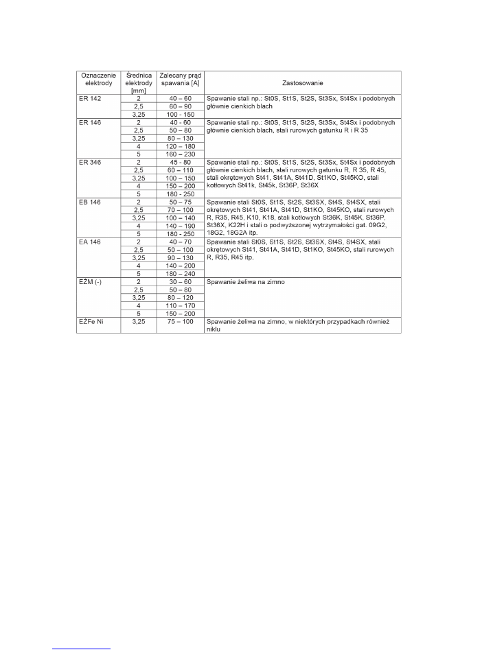
PARAMETERS TABLE PADS
MAINTENANCE AND SERVICE
Maintenance
WARNING!
The electrical shock can cause serious injury or even death. Under no circumstances may touch parts
WARNING!
The electrical shock can cause serious injury or even death. Under no circumstances may touch parts
under voltage wiring such as terminals or the internal components of the device. Prior to the maintenance welder
must be disconnected from the mains.
The device should be cleaned with dry air of low pressure, thereby removing contaminants must be formed on the
housing and the vents. It is necessary for the proper functioning of the device.
An important aspect is the state of the external wiring, welding machines, which need to be checked regularly. In the
event of damage, contact a qualified service welding equipment. Changing the wiring on the other performed inside
the device it is not recommended and may result in denial of warranty. All changes to the wiring should be done by
changing the external wiring.
Changing the power wiring can be performed only by a welding equipment.
18
The most common fault
Warning!
Before any intervention in the welding machine, disconnect the unit from the mains. PROBLEM
Warning!
Before any intervention in the welding machine, disconnect the unit from the mains. PROBLEM
CAUSE
SOLUTION
No voltage outputs
devices
No voltage at the output terminal
After cooling unit,
try to weld.
Inclusion
security
overload
When the power switch device
does not turn on
Damaged
line
control
Please contact an authorized
service center
Defective control board
Service
Repair welding equipment should be carried out by qualified personnel using original spare parts. This ensures the
safety of the device.
REMOVAL OF USED
End of life do not dispose of this product by normal household waste, but take it to a
collection point and recycling of electrical and electronic equipment. This is indicated by the
symbol on the product,
user manual
or packaging. Thanks
re-use, material utilization or other forms of old appliances, you make an important
contribution to protecting our environment.
COMPANY DETAILS
PH Powermat TMK Bijak Sp. General Partnership Ul.
Defenders of the Gdansk Post 97 42-400 Zawiercie

19
DECLARATION OF CONFORMITY