Full Text Searchable PDF User Manual
DUCTLESS MINI SPLIT SYSTEM AIR CONDITIONER/HEAT PUMP
COMPACT CEILING CASSETTE
Installation
Manual
IMPORTANT NOTICE:
Please read this manual carefully before installing
or operating your new air conditioning system.
Be sure to save this manual for future reference.
CAB/CYB Series
CAB: Cooling
-
Only Version
CYB: Cooling and Heating Version
®
®
Inverter+ and Inverter++ Models
9,000
-
18,000 BTU/hr

•
If
used
as a
MULTI
Unit,
please
refer
to
the
Installation
&
O
peration
Manuals
packed
with
the
O
utdoor Unit.
CONTENTS
Page
PRECAUTIONS ................................................................................... 1
INSTALLATION INFORMATION .......................................................... 2
ACCESSORIES ................................................................................... 3
INDOOR UNIT INSTALLATION .......................................................... .4
OUTDOOR UNIT INSTALLATION ..
…
…
…
..
..
..
.
…
…
…
…
…
..
..
..
..
..
…
…
…
…
7
INSTALLING
THE
REFRIGERANT
PIPE
…
…
..
..
..
..
..
.
…
…
…
…
…
..
..
…
..
…
.9
CONNECTING
THE
DRAIN
PIPE..............….....................................12
ELECTRICAL
WIRING
WORK...........................................................13
INSTALLATION OF THE DECORATION PANEL
…
…
…
…
…
…
…
…
…
…
.15
TEST OPERATION ............................................................................ 16
PRECAUTIONS
.
Keep
this
manual in an easily accessible location.
. .
Read
this
manual
extensively
before starting
up
the
units.
.
For safety purposes, any unit operators must read the
following cautions carefully.
Installation
must
be
performed
in
accordance
with
the
requirement
of
NEC
and
CEC,
by
authorized
personnel
only.
The
saf
e
ty
precautions
listed
here
are
divided
into
two
categories.
A
WARNING
If these warnings are not adhered to,
the
unit
may cause
severe property
damage,
personal
injury,
or
loss
of
life.
A
CAUTION
If these cautions are not adhered to,
the
unit
may cause
minor
to
moderate
property
damage or
personal
injury.
Aft
e
r
completing
the
installation,
make
sure
that
the
unit
ope
「
ates
properly
during
the
start-up
operation.
Please
instruct
the
customer
on
how
to
operate
the
unit
and on
keepin
g
it
maintained. Also,
inform
customers that
they
should
store
this
installation
manual,
along
with
the
owner's manual,
for
future
reference.
A
WARNING
Be
sure to only hir
e
trained
and
qualified
service
personnel
to
install, repair,
or
service
the
equipment.
Improper
installation,
repair,
and
maintenance
may
result
in
electric
shocks,
short-circuits,
leaks,
fire,
or
other
damage
to
the equipment.
Install strictly
according
to
these
installation
instructions. If
installation
is
done improperly,
it
can lead to
water
leakage,
electrical shock,
and
fire.
When
installing
the
unit
inside
a
small
room,
take
measures
to
keep the
refrigerant
concentration
from
exceeding allowable
safety
limits,
in
the
event
of
ref
「
igerant
leakage. Contact
the
place
of
purchase
for
mo
「
e
information.
Excessive refrigerant
in
a
closed
ambient environment
can
lead
to
oxygen
deficiency.
Use
the
attached
accessories
and
specified
parts lists
for
installation. Be sure this list is closely adhered to, otherwise, it
can
cause
the
set
to
fall,
or result in water leakage,
electrical
shock,
or
fire.
Install
in
a
strong,
firm
location
that
can
withstand the
entirety of
the set's
weight.
If
the structural
integrity
is insufficient,
or
installation
is
improperly
done, the
set
can possibly
drop
to
cause
injury.
The
appliance
must
be
installed >2.5m/8.2 ft
above the
floor.
The
appliance
must
not
be
installed
in
the
laundry area.
Before
obtaining
access
to
terminals,
all
supply
circuits
must
be
disconnected.
The
appliance
must
be
positioned
so
that
the
plug
is
accessible
.
The
enclosure
of
the
appliance
should
be
marked
by
word,
or
by symbols,
with
the
direction
of
the
fluid
flow.
For
electrical
work,
follow
all
local and
national
wiring
standards
and regulations, as well as these
installation
instructions.
An
independent circuit
and
single
outlet
must
be
used. If the
electrical
circuit
capacity
is
not
enough,
o
「
there is a defect
in
the electrical work,
it
can lead to
electrical
shock
or
fire.
Use
the
specified
cable,
and
tightly connect
and
clamp
the
cable so
that
no
external
force
will
be
acted
upon
the
terminal. If
the connections
or
fixtures
are
not
perfect,
it
can
cause
heat-up
and
eventual fire at
the
connection site.
Wiring
routing
must
be
properly
arranged
so
that the
control
board cover
is
fixed
properly.
If the
control
board
cover
is
not
fixed
perfectly,
it
might
cause
heat-up at
connection
point
of
terminal,
fire,
or
electrical
shock.
If the
supply
cord
is
damaged,
it
must
be
replaced
by
the
manufacturer, service
agent,
or
a
similarly
qualified
person, in
order
to
avoid
a
hazard.
An
all-pole
disconnection
switch,
having
a
contact
separation of
at
least
3mm
in
all
poles,
should
be
connected
to the
fixed
wiring.
When
carrying
out the
piping
connections,
take
care to not
allow air particles infiltrate
into
「
efrigeration
cycle.
Otherwise,
it
can
cause diminished
capacity,
abnormally
high
pressure in
the
refrigeration
cycle,
explosion,
or
injury.
Do
not
modify
the
length
of
the
power
supply
cord,
or
use
an
extension
cord,
and
do
not
share
the
isolated
outlet
with
other
electrical
appliances. Otherwise,
it
can result in
fire
or
electrical
shock.
1
If
the
refrigerant
leaks
during
installation,
ventilate
the
area
immediately.
Toxic
gas
may
be
produced
if
the
refrigerant
comes
into
contact
with
fire.
The
temperature
of
the refrigerant
circuit
will
be
high, so
please
keep
the
interconnection
cable
away
from
the
copper
tube.
Afer
completing
the
installation
work,
check
that
the
refrigerant
does
not
leak.
Toxic
gas
may
be
produced
if
the
refrigerant
leaks
into the
room
and
comes
into
contact
with
a
source
of
fire,
such
as
a
fan
heater,
stove,
or
cooker.
A
CAUTION
Ground
the
air
conditioner.
Do
not
connect
the
ground
wire
to any
gas
or
water
pipes,
lightning
rods,
or
telephone
ground
wires. Improper
grounding
may
result
in
electric
shocks.
Be
sure
to
install
an
earth
leakage
breaker. Failure
to
install
an
earth
leakage
breaker
may
result
in
electrical shocks.
Connect
the
outdoor
unit
wires first before
connecting
the
indoor
unit wires.
It is not permitted to
connect
the
air
conditioner
to
the
power
supply
until
the
wiring
and
piping
is
done.
While
following
the
instructions
in
this
installation
manual,
install
the drain
piping
in
o
「
der
to
ensure
prope
「
drainage,
and
insulate
the piping
in
order
to
prevent
condensation. Improper
drain
pipe
configuration
may
result
in
water
leakage
and
property
damage.
Installing
the
indoor
and
outdoo
「
units:
powe
「
supply
wiring
and
connecting
wires
should
be
at
least
1
meter
away
from
televisions
or
radios,
in
order
to
prevent
image
interference
or
noise.
Depending
on
the
radio
waves,
a
distance
of
1
meter
may
not
be
sufficient
to
eliminate
all
noise interference.
The
appliance
is
not
intended
for
use
by
young
children
o「
infirm
persons
without
supervision.
Don't
install
the
air
conditioner
in
the
following
scenarios:
•
There
is
petrolatum
present.
•
There
is high-salinity air in the surrounding area.
•
The
「
e
is
caustic
gas
(sulfide,
for
example)
present
in
the
air
(e.g. near
hot
springs).
•
There are voltage fluctuations
(like in
factories).
•
In
buses
or
cabinets.
•
In
kitchens
with a high presence of
oily
gases.
•
Areas with
s甘ong
electromagnetic
waves
• There are inflammable materials or gas.
• There is acid or alkaline liquid evaporating.
• Other special conditions.
The appliance shall be installed in accordance with national
wiring regulations.
Do not operate your air conditioner in a wet room such as a
bathroom or laundry room.
An all-pole disconnection device which has at least 3mm I 0.1 in
clearances in all poles , and have a leakage current that may
exceed 1 OmA, the residual cur「ent device (RCD) having a rated
residual operating current not exceeding 30mA, and
disconnection must be incorporated in the fixed wiring in
accordance with the wiring rules.
INSTALLATION INFORMATION
.
To install properly, please read this "installation manual" at
first.
.
.
The air conditioner must be installed by qualified persons.
When installing the indoor unit or its tubing, please follow
this manual as strictly as possible.
.
If the air conditioner is installed on a metal part of the
building, it must be electrically insulated according to the
relevant standards to electrical appliances.
.
.
When all the installation work is finished, please turn on
the power only after a thorough check.
Regret for no further announcement if there is any change
of this manual caused by product improvement.
INSTALLATION ORDER
•
Indoor unit installation;
•
Outdoor unit installation;
•
Install the refrige
「
ant pipe;
•
Connect the drain pipe ;
•
Electric wiring work;
•
Installation of the decoration panel;
•
Test operation.
2
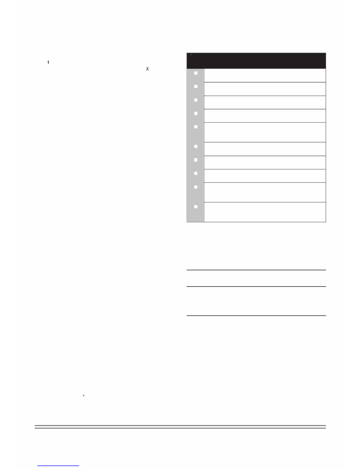
ACCESSORIES
Check if the following accessories are included with your un几
For the following items, take special care during
construction and check after installation is finished
2
3
|
伙
:
厂
4P—什凸
6a
5
尸夕丿
9
10
;
;
12
尸
11
厂
1 Remote controller
2 Batteries
7
尸
11
;
5
3 Remote controller holder (on some models)
4 Tapping screws (M3X 10mm) (on some models)
5
Installation
and
O
wner's
Manual
丿
8
12
Tick
when
checked
门
Is
the
indoor
unit
fixed
firmly?
The
unit
may
drop. vibrate
,
or
make
noise.
口
Is
the
gas
leak
test
finished?
It
may
result
in
insufficient
cooling
or
heating.
口
Is the unit fully insulated?
Condensate water may drip.
口
Does drainage flow smoothly?
Condensate water may drip.
口
Does the power supply voltage correspond to that
shown on the name plate?
The unit may malfunction or components may burn out.
口
Are wiring and piping correct?
The unit may malfunction or components may burn out.
口
Is
the
unit
safely
grounded?
Dangerous
if there is an
electric
leakage.
口
Is
the
wiring
size
according
to
specifications?
The unit may malfunction or components may burn out.
口
Is nothing blocking the air outlet or inlet of either the
indoor or outdoor units?
It may result in insufficient cooling or heating.
口
Are refrigerant piping length and additional refrigerant
charge noted down?
The
refrigerant
charged
in
the
system
might
not
be
clear.
A
NOTE
6
Paper
pattern
for
installation
(on
some
models)
All
pictures
in
this
manual
are
for
explanatory
purposes
only.
7
Metal
Clamp
(on
some
models)
There
may
be
slightly
differences
from
the
air
conditioner
you
purchased
(depending
on
model).
The
actual
shape will
preva仆
8
Drain
H
ose
(on
some
models)
9
Expansible
H
ooks
(on
some
models)
10
Installation
H
ooks
(on
some
models)
11
Throttle
(on
some
models)
12
Anti-Shock
Rubber
(on
some
models)
13 Drain Plug (only heat pump models)(with the outdoo
「
unit)
14 Seal Ring(only heat pump models)(with the outdoor unit)
Opt"
1onal
A
ccessories
•
This indoor unit requires installation of an
separate
decoration
panel.
3

1.
INDOOR
UNIT
INSTALLATION
1.1
Selecting t
he
I
nstallation
Site
When
the
conditions
in
the
ceiling
exceed
30
°
C/86
°
F
and
a relative
humidity
of
80%,
or
when
fresh
air
is
inducted
into
the
ceiling, an
additional
insulation layer
is
required
(minimum
10
mm/ 0.4in
thickness,
polyethylene
foam).
1)
Select
an
installation
site
where
the
following
conditions
are
fulfilled,
and
also
that
meets
your
customer's
approval.
-
Where
optimum
air
distribution
can
be
ensured.
-
Where
nothing
blocks
the air
passage.
-
Where
condensate
water
can
be
properly
drained.
-
Where
the
false
ceiling
is
not
on
on
a considerable
incline.
-
Where
sufficient
clearance
for
maintenance
and
service
can
be
ensured.
-
Where
there
is
no
「
isk
of
flammable
gas
leaking.
-
Where it will not be at risk of being near to
potentially
explosive
atmospheres.
-
Where
piping
between
indoor
and
outdoor
units
is
possible
within
the
allowable
limit. (Refer
to
the
installation
manual
of
the
outdoor
unit.)
-
Keep
indoor
unit. outdoor
unit. inter-unit
wiring,
and
remote
controller
wiring
at
least
1
meter
away
from
televisions
and
radios. This
is
to
prevent
image
interference
and
noise
in
those
electrical
appliances. (Noise
may
be
generated
depending
on
the
conditions
under
which
the
electric
wave
is
generated,
even
if a
1
meter
separation distance is
kept.)
-
When
installing
the
wireless
remote
controller
kit, the
distance
between the
wireless
remote
controller
and
indoor
unit
might
be
shorter
if
there
are
fluorescent
lights
that
are
electrically
started
inside
the
room. The
indoor
unit
must
be
installed
as
far away
as
possible
from
fluorescent
lights.
2)
Ceiling
H
eight
Install
this
unit
where
the
height
of
bottom
panel
is
greater
than
2.5m
I
8.2ft above ground
so
that
users
do not
easily
touch it.
3)
Use
installation
hooks
for
installation. Check
whether
the
ceiling
is
strong
enough
to
support
the
weight
of
the
indoor
unit. If
there
is
a
structural integrity
risk, reinforce
the
ceiling
before
installing
the
unit.
Space
required
fo
「
installation:
see
the next
figure
(仑: air
flow
direction)
\
I
-
l
__
.
.
.
.
.
.
.
..
-
•
•
•
•
•
•
•
•
•
•
.
.
.
.
.
.
.
.
.
.
·
•
·
•
·
•
·
•
•
·
•
•
•
•
•
•
•
•
•
•
•
•
•
•
•
•
•
•
•
•
·
•
•
•
·
•
·
•
•
·
•
•
•
•
•
•
•
•
•
•
•
•
•
•
•
•
•
•
•
•
•
•
•
•
•
•
•
•
•
•
•
•
•
•
•
•
•
•
•
•
•
•
•
•
•
•
•
•
•
•
•
•
•
•
•
•
•
•
•
•
..
• I
••
I··,
.••
l`
.
....
..
..
..
.
啊u
o
l
-
I
\
1/
12
Air Inlet
Air
O
utlet
Unit: mm
A
DANGER
Do
not
install
the
unit
in
an
area
where
flammable
materials
are
present
due
to
risk
of
explosion, which can
result
in
serious
injury,
or
death.
A
WARNING
If
the
base
underneath
the
unit
is
not
strong
enough
to
support
the
weight
of
the
unit,
the
unit
could
fall
out
of
place
and
cause
se
「
ious
injury.
4

1.2
1)
Preparations
B
efore
I
nstallation
Relation
of
ceiling
opening
to
unit
and
suspension
bolt
position.
4
5
U!S
'SZ/L寸9
LIWWOLS
u19
·ozt£ZS
�INIM
1-2-3
545/21.Sin
570/22.4in
647/25.Sin
2)
Make
the
ceiling
opening
needed
for
installation
where
applicable. (For
existing
ceilings.)
-
Create
the
ceiling
opening
required
for
installation. From
the
side
of
the
opening
to
the
casing
outlet,
implement
the
refrigerant
and
drain
piping
and
wiring
for
remote
controller
(unnecessary
for
wireless
type).
Refer
to
each
piping
or
wiring
section.
-
After
making
an
opening
in
the
ce由ng,
it
may
be
necessary
to
reinforce
ceiling
beams
to
keep
the
ceiling
level,
and
to
prevent
it
from
vibrating.
Consult
the
builder
for
details.
3)
Install
the
installation
hooks.
(Use
either a MS
or
M10
size
bolt.)
Use
expansible
hooks,
sunken
anchors,
or
other
field
supplied
parts
to
reinforce
the
ce仆ing
in
order
to
bear
the
weight
of
the
unit.
Adjust
clearance
from
the
ceiling
before
proceeding
further.
Installation
example:
see
figure
below.
3
I
:\
\\\
\
\
\;
4
1234567
8
Unit:mm
Installation
Hook
P
itch
dimensions
Indoor
U
nit
dimensions
D
ecoration
P
anel
dimensions
Refrigerant
P
iping
Installation
Hook
(X4)
Ceiling
opening
dimensions
Hanger
B
racket
False
Ceiling
1234
Ceiling
slab
Expansible
hook
(optional)
Installation
hook
(optional)
False
ceiling
NOTE
.
For
other
non-
standard
installation
s
,
contact
your
dealer
for
details.
.
Adjust
positions
to
ensure
the
gaps
between
the
Indoor
unit
and
the
four
sides
of
false
ceiling
are
even.
The
indoor
unit's
lower
part
should
sink
into
the
false
ceiling
for
24mm
I 0.9in.
乙
VII/
12
Indoor
U
nit
False
Ceiling
NOTE:
Installation
is
possible
with
a
ceiling
dimension
of
600
mm
/
23.6in (marked
with *).
However, to
achieve
a
ceiling-panel
overlapping
dimension
of
15
mm/
0.6in,
the
spacing
between
the
ceiling
and
the
unit
should
be
20
mm
I 0.8in
or
less. If
the
spacing
between ceiling
and
the
unit
is
ove
「
20
mm
I
0.8in,
attach
sealing
mate
「
ial
in
the
part or
recover
the
ceiling.
5
1.3 Installin
g
the Indoor
U
nit
When
installing
optional
accessories,
read
the
installation manual
of
the
optional
accessories as well.
Depending
on
the
field
conditions,
it
may
be
easier
to
install
optional
accessories
before
the
indoor
unit
is
installed
(except
for
the
deco「ation
panel).
However,
for
an existing
ceiling,
install a
fresh
air
inlet
component
k仆 and
b
「
anch
duct
before
installing
the
unit.
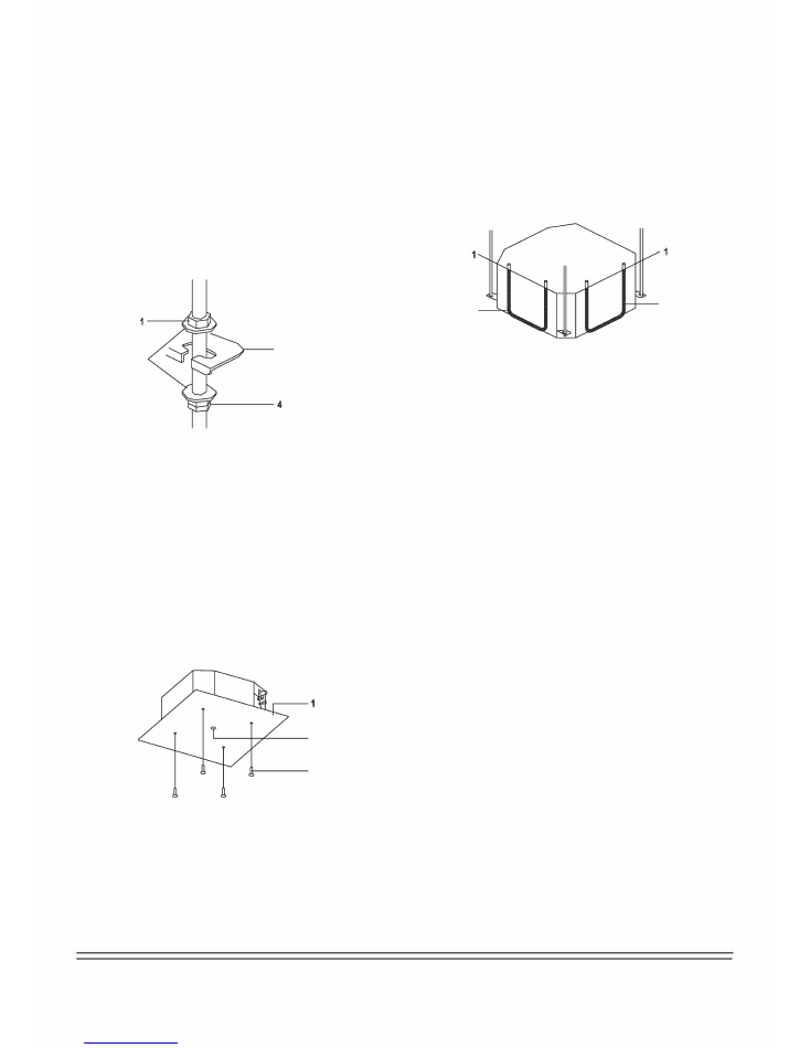
1)
Install
the
indoor
unit
temporarily.
-
Attach
the
hanger
bracket
to
the
suspension
bolt.
Be
sure
to
fix
it
securely
by
using
a
nut
and
washer
from
the
upper
and
lower
sides
of
the
hanger
bracket.
-
Securing
the
hanger
bracket
:
see
figure
below
4)
Check
that
the
unit
is
horizontally
levelled.
-
Do
not
install
the
unit
tilted.
The
indoor
unit
is
equipped
with
a
built-in
drain
pump
and
float
switch.
(If
the
unit
is
tilted
against
the
direction
of
the
condensate flow
(the
drain
piping
side
is
raised),
the
float
switch
may
malfunction
and
cause
water
to
drip.)
-
Check
that
the
unit
is
levelled
at
all
four
come
「
s
using
a
water
level, or
a
water-filled
vinyl
tube,
as
shown
in
figure
below.
2
2
3
2
1
Water
level
2
Vinyl
Tube
5) Remove the paper pattern for Installation. (For new celling
only).
1
Nut (field supply)
2
Washer (field supply)
3
Hanger Bracket
4
Double Nuts (field supply,tighten)
2) Fix the paper pattern for installation. (For new ceilings only)
- The paper pattern fo
「
installation co
「
responds with the
measurements of the ceiling opening. Consult the builder for
details.
- The centre of the ceiling opening is indicated on the paper
pattern for installation.
- After removing the packaging material from the paper patten for
installation, attach the paper pattern for installation to the unit
with the attached sc「ews as shown in figure below.
2
3
1
Pape
「
P
attern
to
「
I
nstallation(on
some
models)
2
Center
of
the
C
eiling
O
pening
3
Screws(supplied
with
the
decoration
panel)
3)
Adjust
the
unit
to
the
correct
position
for
Installation.
(Refer
to
the
chapter
"Preparations
before
I
nstallation"
on
page
5.)
6
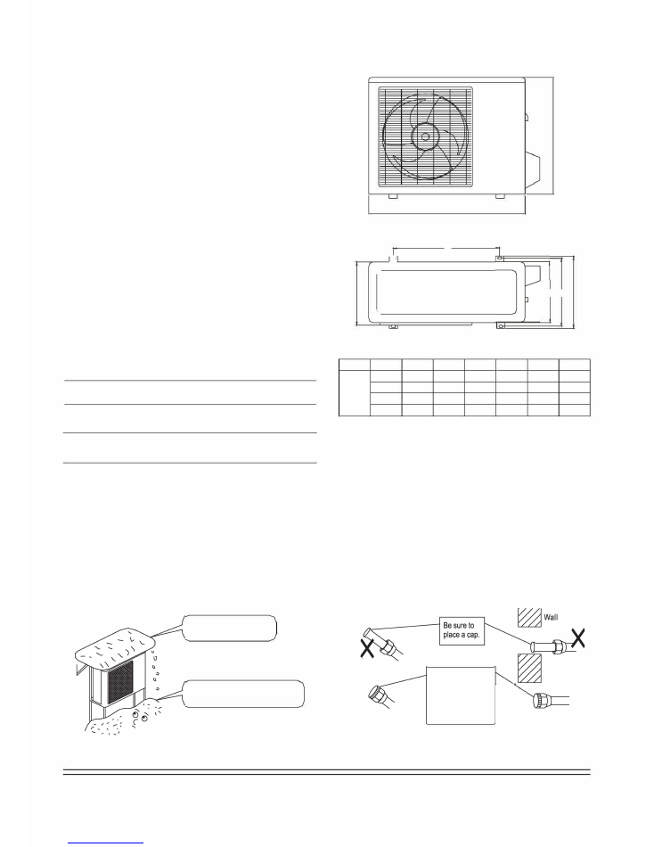
2.2 Figure
of
B
ody
S
ize
2.
OUTDOOR
UNIT
INSTALLATION
2.1
Precautions
for
Location Selection
1)
Choose
a
place
sturdy
enough
to
bear
the
weight
and
vibration
s
of
the
unit,
and
where
the
operation
noise
will
not
be
amplified.
2)
Choose
a
location
where
neither
the
hot
air
discharged
from
the
unit
n
or the
operation
noise
will
cause
a
nuisance
to
the
neighbors of
the
user.
3)
Avoid
places
near
bedroom
s
and
the
like,
so
that
the
operation
noise
will
cause
no
disturbances.
4)
There
must
be
sufficient
space
for
carrying
the
unit
into
and
out
from
the
site.
5)
There
must
be
sufficient
space
for
air
passage,
and
no
obstructions
around
the
air
inlet
and
the
air
outlet.
6)
The
site
must
be
free
from
the
poss心lity
of
flammable
gas
leakage
in
a
nearby
place.
7)
Install
units,
power
cords,
and
inter-unit
wire
at
least
3m
away
from television
and
radio
sets.
This
is
to
prevent
interference
from
images
and
sounds.
(Noises
may
be
heard
even
if
they
are
more
than
3m
away,
depending
on
radio
wave
cond仆ions.)
8)
In
coastal
areas,
or
other
places
with
salty
atmosphere,
o
r
sulfate
gas,
corrosion
may
shorten
the
life
of
the
air
conditioner.
9)
Since
drain
flows
out
of
the
outdoor
unit,
do
not
place
anything
underneath the
unit that
must
be
kept
away
from
moisture
NOTE:
Cannot
be
installed
hanging
from
ceiling,
or
stacked.
A
CAUTION
When
operating
the
air
conditioner
in
a
low
outdoor
ambient
temperature,
be
sure
to
follow
the
instructions described
below.
-
To
prevent
exposure
to
wind,
install
the
outdoor
unit
with
its
suction
side
facing
the
wall.
-
Never
install
the
outdoor
unit
in
a
site
where
the
suction
side
may
be
exposed
directly
to
wind.
-
To
prevent
exposure
to
wind,
it
is
recommended
to
install
a
baffle
plate
on
the
air
discharge
side
of
the
outdoor
unit.
-
In
heavy
snowfall
areas,
select
an
installation
site
where
the
snow
will
not
affect
the
unit.
工
A
B
-
ID一
LL
,
-
J
山1010
Unit:mm
MODEL
A
B
C
E
D
H
F
780
548
266
300
241
250
540
9K-18K 760
530
290
315
270
285
590
810
549
325
350
305
310
558
845
560
335
360
312
320
700
(in
=
mm/25.4)
1)
Caution
on
pipe
handling
•
Protect
the
open
end
of
the
pipe
against
dust
and
moisture.
•
All
pipe
bends
should
be
as
gentle
as
possible.
Use
a
pipe
bender
for
bending.
- Construct a la「ge canopy.
- Construct a pedestal.
Install the unit high enough off the
ground to prevent burying in snow
Rain
11'I'
''ii:
I I 1
If no flare cap is
available, cover the
flare mouth with
tape to keep dirt or
water out.
归
7
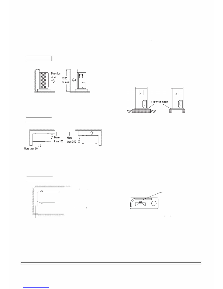
2.3
Installation
G
uidelines
•
When
a
wall,
or
other
obstacle,
is
in
the
path
of
outdoor
unit's
inlet
or
outlet
airflow,
follow
the
installation
guidelines
below.
•
For
any
of
the
below
installation
patterns,
the
wall
height
on
the
outlet
side
should
be
1200mm/47.2in,
or
less.
I
Against a straight wall
More than 100
More than 350
Side view
Against corner wall
2.4
Outdoor
U
nit Installation
1)
Installing
Outdoor
U
nit
:
•
When
installing
the
outdoor
unit,
refer
to
"Precautions
for
Location Selection
"
•
Check
the
sturdiness
of
the
installation
ground
so
that
the
unit
will
not
cause
any
operating
vibration
or
noise
once
installation is complete.
•
Fix
the
unit securely
by
means
of
foundation
bolts.
(Prepare
4
sets
of
M8
or
M10
foundation
bolts,
nuts,
and
washers,
each
which
are
available
on
the
ma
「
ket.)
2) Drain
W
ork
More than 50
Top view
•
If
drain
work
is
necessary,
follow
the
procedu「es
below.
•
Use
a drain
plug
for
drainage.
•
If
the
drain
port
is
covered
by
a
mounting
base
or
floor
surface,
place
additional
foot
bases,
of
at
least
30mm/1.2 in
in
height,
underneath
the
outdoor
unit's
feet.
I
Against 3-sided wall
I
.
笏
g
0
O
0
5
1
3
n
n
a
a
h
h
t
一.
re
re
0
O
M
M
7
「
勹
二
In
cold
areas,
do
not
use
a
drain
hose
with
the
outdoor
unit.
(Otherwise, the
drain
water
may
freeze,
impairing
heating
performance.)
D
「
ain
port
More than 50
Top view
Unit:mm
(in=mm/25.4)
Bottom !came
勹二::::''"'
8
I
I
3
INSTALLING
THE REFRIGERANT PIPE
A
All field piping must be provided by a licensed refrigeration
technician, and must comply with all relevant local and
national codes.
Precautions
•
Execute heat insulation work to completion on both sides of the
gas piping and liquid piping. Otherwise, it can sometimes result
in water leakage.
(When using a heat pump, the temperature of the gas piping can
°
reach up to approximately 120'C/248 F. Use insulation that has
sufficient resistance.)
•
Also, in cases where the temperature and humidity of the
°
refrigerant piping sections might exceed 30'C/86 F or Rh80%,
reinforce the refrigerant insulation (by 20mm/0.8in, or thicker).
Condensation may form on the surface of the insulating material.
•
Before rigging tubes, check which type of refrigerant is used
•
Use a pipe cutter and flare suitable for used refrigerant.
•
Only use annealed material for flare conncetions.
•
Do not mix anything other than the specified refrigerant, such
as air, etc.., into the refrigerant circuit.
•
If the refrigerant gas leaks during the work, ventilate the area.
A toxic gas is at risk of being emitted by the refrigerant gas if
exposed to a fire.
•
Make sure there is no refrigerant gas leak. A toxic gas may be
released by the refrigerant gas leaking indoors and being
exposed to flames from an area heater, cooking stove, etc.
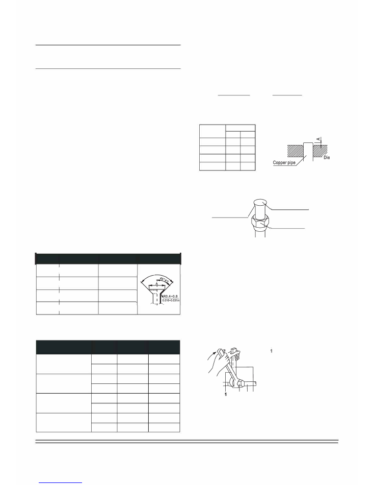
•
Refer to the table below for the dimensions of flare nuts spaces
and the appropriate tightening torque. (Overtightening may
damage the flare, and cause leaks.)
I
Pip(�
g
�)
uge
Tightening torque
Fla「e
飞$霄
sion
Flare shape
I
15-16N m
8 3-8 7
邵.35(1/4叫 (153-163 kgf.cm)
0.327-0.343in
90
。
土4
25-26 N. m
12.0-12.4
[?Jg 52(3/Sin) I (255-265 kgf.cm) 0.472�0.488in
35-36 N. m
15.4-15.8
012 1(112inll (357-367 kgf.cm)
0.606-0.622in
0159(5/8m)I
45-47 N. m
18.6-19.0
(459-480 kgfcm)
0.732-0.74Bm
•
Check whether the height drop between the indoor unit and
outdoor unit, as well as the length of refrigerant pipe, meet the
following requirements:
Capacity Max.allowable Max.allowable
Model Type
(Btu/h)
piping length piping height
9K-12K
25m/82ft
10m/33ft
R410A inverter
Split type ai「 conditione「
18K
30m/100ft
20m/66ft
3.1 Flaringthe Pipe
E
nd
s
1) Cut the pipe end with a pipe cutter.
2) Remove burrs with the cut surface, facing downward so that
the chips do not enter the pipe.
c""""'"
ID
right angles. / I�Remove burrs
3) Put the flare nut onto the pipe.
4) Flare the pipe.
(in
=
mm/25.4)
Set exactly at the position shown below.
Oute「 diam.
A(mm)
(mm)
Max. Min.
邵35(1/4in) 1.3
0.7
邵.52(3/Bin) 1 6
1 0
如2.7(1/2in) 1 8
1 0
如5.9(5/Bin) 22
20
5) Check that the flaring is properly made.
Flare's inner surface
mustbe free of flaws
The pipe end must
be evenly fla
「
ed in a
perfect circle.
Make sure that the
flare nut is fitted.
3.2 Refrigerant Piping
•
Coat the flare, both inside and outside, with ether oil or ester oil
C
�
oa
�
t here with ether oi
厂
l or ester oil
•
Align the centres of both fla「es, and tighten the flare nuts 3 or 4
turns by hand. Then tighten them fully with the torque wrenches
Torque wrench
2
Flare nut
3
Piping union
4
Spanner
2 3 4
9
Page
10
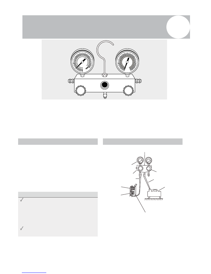
Air Evacuation
9
Preparations and Precautions
can cause abnormal rises in pressure, which
can damage the air conditioner, reduce its
efficiency, and cause injury. Use a vacuum pump
and manifold gauge to evacuate the line set and the
indoor unit, removing any non-condensable gas
and moisture from the system.
Evacuation should be performed upon initial
installation, and when unit is relocated.
BEFORE PERFORMING EVACUATION
Check to make sure that both LIQUID
SIDE and GAS SIDE pipes between
the indoor and outdoor units are
connected properly, in accordance with the
Refrigerant Piping Connection section of
this manual.
Check to make sure all wiring is connected
properly.
Evacuation Instructions
Before using the manifold gauge and vacuum
pump, read their operation manuals to familiarize
yourself with how to use them properly.
Manifold Gauge
Low pressure gauge
-76cmHg
Low Pressure Valve
High Pressure
Valve
Blue (low) Hose
Yellow (middle) Hose
Vacuum
Pump
High Pressure Gauge
Outdoor Unit Service Valve Set (GAS and LIQUID Valves)
1.
Connect the blue (low side) hose of the manifold
gauge to the service port on the outdoor unit’s
GAS SIDE valve (use a 1/4” to 5/16” port adapter if
needed, which is sold separately)
2.
Connect the yellow (middle or common ) hose from
the manifold gauge to the vacuum pump.
MC
MC
Fig. 6.1
Air and foreign matter in the refrigerant circuit
BLUE (Low Pressure) Side of Manifold Gauge
RED (High Pressure) Side of Manifold Gauge
YELLOW (Common) Side of Manifold Gauge
BLUE (Low Pressure) Gauge
RED (High Pressure) Gauge
Low Pressure Valve
High Pressure Valve
LARGE DIA (GAS)
Service Valve
SMALL DIA (LIQUID)
Service Valve
Caution: Systems are precharged with refrigerant (entire amount necessary for the system set has been
charged into the outdoor section). The line sets and the indoor units are not charged, and must be evacuated
prior to releasing the refrigerant from the outdoor unit to the rest of the system.
Do NOT open the valves of the 2 service ports on your outdoor unit until the air evacuation is completed
successfully, and thw system passes leak checks. BOTH of those Service valves MUST BE OPENED to release the
refrigerant before turning the system ON. Operating the system with service valves closed will result in
compressor damage.
Page
11
Air
Evacuation
3.
Open the BLUE (Low Pressure) valve of Manifold
Gauge. Keep the RED (High Pressure) valve closed.
4.
Turn the vacuum pump ON to start evacuating the
air from the line set and indoor unit circuits.
5.
Run the vacuum pump for at least 15 minutes, or
until the Low Pressure Gauge reads -76cmHG
(-100 kPa or -30 In Hg). (Negative value)
6.
Close the Blue (Low Pressure) valve of Manifold
Gauge, then turn the vacuum pump OFF.
7.
Wait for 5 minutes, then check that there has
been no rise in Low Pressure Gauge reading.
8.
If there is a rise (Vacuum Loss), refer to the
Gas Leak Check section for information
on how to check for leaks. If there is no
change in vacuum reading, unscrew the cap
from the LIQUID Side Service Valve (Fig. 6.2)
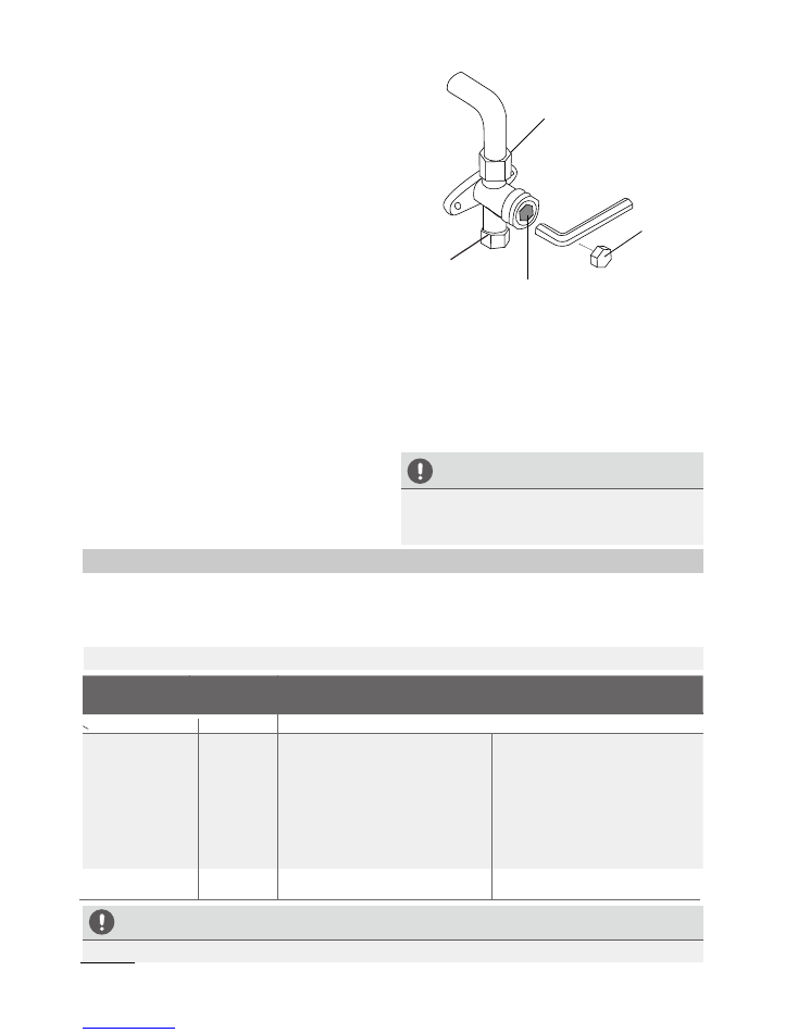
9.
Insert a hexagonal wrench into the service valve
(LIQUID Side Valve), and open the valve by
turning the wrench in a 1/4 counterclockwise
turn. Listen for the sound of gas exiting the
system, then close the valve after 5 seconds.
10.
Watch the Pressure Gauge for a few minutes,
to make sure that there is no drop in the
pressure value (indicating a leak)
The Low Pressure Gauge should now show
a positive pressure value (Above Zero).
Flare Nut
Hexagonal
Dust Cap
Valve Core
11.
Remove the charging hose from the service port.
12.
Using a hexagonal wrench, fully open both the
LIQUID side and GAS side Service Calves.
13.
Tighten valve caps on all three valves (service
port, liquid side, gas side) by hand.
Then, tighten it further using a torque
wrench, if needed.
OPEN VALVE STEMS GENTLY
When opening valve stems, turn the hexagonal
wrench until it seats against the stopper. Do not
try to force the valve to open further.
Note on Adding Refrigerant
ADDITIONAL REFRIGERANT PER PIPE LENGTH
Connective Pipe
Length (m)
Air Purging
Method
Additional Refrigerant
< Standard pipe length Vacuum Pump
N/A
> Standard pipe
length (5m/~16’)
Vacuum Pump
Liquid Side: Ø 6.35 (ø 1/4”)
Gas side either
Ø 9.52 (ø 3/8”) or
Ø 12.7 (ø 1/2”)
Add for lengths beyond 5m (16 feet)
(Per additional meter) x 15g /m
(Per additional foot) x 0.16 oz/ft
CAUTION
DO NOT
mix refrigerant types. Be sure to use only the same type of refrigerant (R410a).
Fig. 6.2
Some systems require additional charging depending on pipe lengths. The pipe length varies according
to locations of the indoor and outdoor units. The system has been factory charged with sufficient R410a
refrigerant for the standard pipe length of 5m (~16‘). The additional refrigerant to be charged can be
calculated using the following formula. This is necessary only if the length exceeds 7.5m (25 feet).
Liquid Side: Ø 9.52 (ø 3/8”)
Gas side either
Ø 15.87 (ø 5/8”) or
Ø 19.05 (ø 3/4”)
Add for lengths beyond 5m (16 feet)
(Per additional foot) x 0.32 oz/ft
(Per additional meter) x 30 g/m
Copper Pipe from Indoor Unit
Service Port
(Only the GAS Side
Valve has this port)
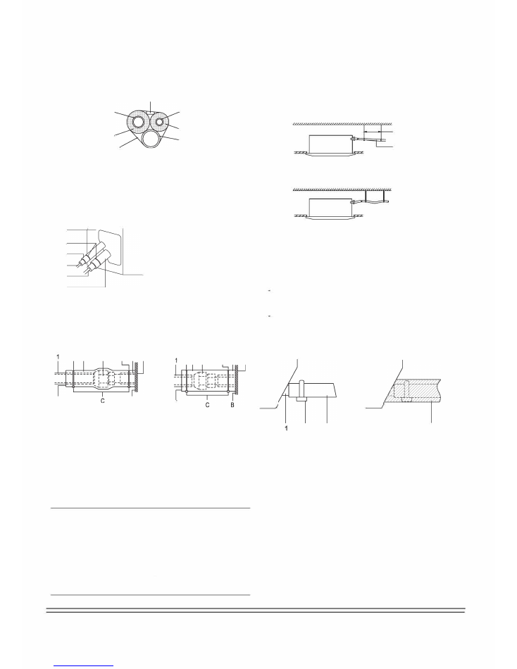
2) Be sure to insulate both the gas and liquid piping. Use
separate thermal insulation pipes for gas and liquid
refrigerant pipes. See the figure below.
Inter-unit wi
『
e
Gas pipe
Gas pipe
insulation
Finishing tape
Liquid pipe
Liquid pipe
insulation
Drain hose
3) Finally, insulate as shown in the figure below.
6
5
3
1
2
4
三
12345
6
Liquid pipe
Gas pipe
Insulation for liquid pipe fitting
Insulation for gas pipe fitting
Clamps
(use 2 clamps per insulation)
Indoor unit
4
CONNECT THE DRAIN PIPE
4.1 Installation of Drain Piping
Install the drain piping as shown in figure below, and take measures
against condensation. Improperly「igged piping could lead to leaks,
and eventually wet furniture and belongings.
1-1.Sm
3-51!
1
2
X
12
Hanging bar
1/100 gradient
Piping insulation procedure
_
6
3
2
6
4
5
A
B
_
A
123456
ABC
6 3
2
Piping insulation material(field supply)
Fla「e nut connection
Insulation for fitting (field supply)
Piping insulation material (main unit)
Indoor un仆
Clamp (field supply)
Turn seams up
Attach to base
Tighten the part other than the piping insulation mate
「
ial
6
4
5
A
.
.
For local insulation, be sure to insulate local piping
all the way into the pipe connections inside the unit.
Exposed piping may cause condensation, or may
cause burns when touched.
Make sure that no oil remains on plastic parts of the
decoration panel (optional equipment).
Oil may cause degradation and damage to plastic
parts.
4.2
Install the drain pipes.
Keep piping as short as possible, and slope it downwards at
a gradient of at least 1/100 so that air may not remain
trapped inside the pipe.
Keep pipe size equal to or greater than that of the connecting
pipe (PVC pipe, nominal diameter 20mm/0.8in in, outside
diameter 25mm/1in).
- Push the drain hose as far as possible over the drain socket,
and tighten the metal clamp securely.
3
2
3
4
1234
D
「
ain socket (attached to the unit)
metal clamp
Drain hose
Insulation (field supply)
- Insulate the drain hose inside the building.
- If the drain hose cannot be sufficiently set on a slope, fit the
hose with d
「
ain raising piping (field supply).
- Make sure that heat insulation work is executed on the
following 2 spots to prevent any possible water leakage due
to dew condensation.
1 Indoor drain pipe.
2 Drain socket.
12
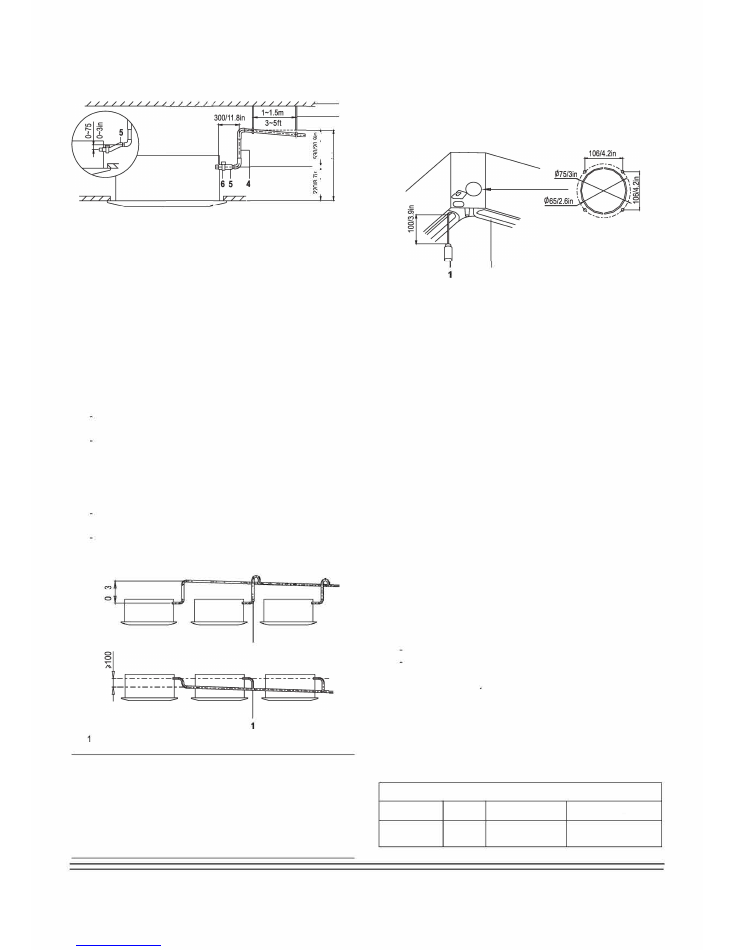
4.3 How to
Perform Pipework
4.4 Testing of
D
rain
P
iping
After the piping work is finished, check if drainage flows smoothy
1
2
.
U19
"6l/09l
u15·oz1m:s
'I'u1L·e1ozz
3
Add approximately 1 L of water gradually through the air discharge
outlet.
Method of adding water (see the figure below):
Unit:mm
123456
Ceiling Slab
Hanger Bracket
Adjustable
R
ange
Drain
R
aising Pipe
Drain
H
ose
Metal Clamp
F
「
esh air intake (中65/2.6in)
2
Unit: mm
12
Plastic watering can(tube should be about 100 mm/3.9in long)
Water-receiver
- Connect the drain hose to the drain raising pipes, and
insulate them.
- Connect the drain hose to the drain outlet on the indoor unit,
and tighten it with the clamp.
.
When electric wiring work is finished, check drainage flow during
COOL running
mode
, explained in "Test Operation" on page 16.
.
Precautions
Install the drain raising pipes at a height
lower
than 530
mm/20.9 in.
Install the drain raising pipes at a right angle to the indoor unit,
and no more than 300 mm/11.8 in. from the unit.
- To prevent air bubbles, install the drain hose level, or slightly
tilted up ('i,75 mm/3 in.).
- The incline of
the
d
「
ain hose should be 75 mm/3 in. o
「
less, so
that the drain socket does not have to withstand additional force.
To ensure a downward slope of 1:100, install hanging
bars every 1m/3.3ft to 1.5 m/4.9ft.
When unifying multiple drain pipes, install the pipes asshown in
the
figure below. Select converging drain pipes whose gauge is
suitable for the operating capacity of the un仆
C>
----
- ---
- -
"?
I
I
,
1
Unit:mm
T-joint converging d
「
ain pipes
A
.
.
Drain piping connections
Do not connect the drain piping directly to sewage
pipes that smell of ammonia. T he ammonia in the
sewage might enter the indoor unit through the drain
pipes, and corrode the heat exchanger.
Keep in mind that it will be the cause of
the
drain
pipe
getting
blocked if water collects on drain pipe.
5
ELECTRIC
AL
WIRING WORK
General
I
nstructions
.
•
•
.
.
..
All field wiring and components must be installed by a licensed
electrician and must comply with relevant European and national
regulations.
Use copper wire only
Follow the' Wiring diagram' attached to the unit body to wire the
outdoor unit, indoor units, and the remote controller.
A circuit breaker capable of shutting down
the
power supply to
the entire system must be installed.
Note that the operation will restart automatically if the main
power supply is turned off and then turned back on again.
Be sure to ground the ai
「
conditioner.
Do not connect the ground wire to gas pipes, water pipes,
lightning rods, or telephone ground wires.
- Gas pipes: might cause explosions or fire if gas leaks
Water pipes:no grounding effect if hard vinyl piping is used.
Telephone ground wi
「
es o
「
lightning rods: might cause
abnormally high electrical potential in the ground during
lightning storms
Circuit breaker/Fuse(A)
Power Specifications
Power
Model
Phase
Frequency and volt
9K-1BK
1Phase
20 8-240V
20/16
13
.
.
How to
C
onnect t
he
W
iring
.
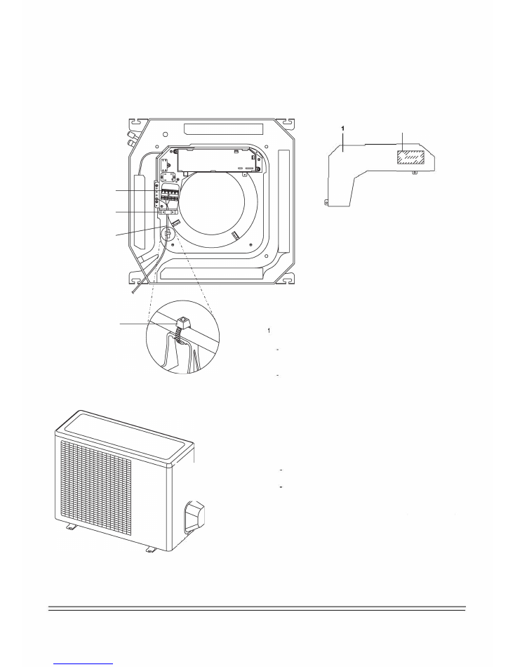
Remove the control box lid of the indoor unit.
Remove the cover of the outdoor unit.
Follow the "Wiring diagram label" attached to the indoor unit's control box lid to wire the outdoor unit, indoor unit, and the remote controller.
Securely fix the wires with a field supplied champ.
Reattach the cover of the outdoo
「
unit.
3
4
5
6
J
令
7
呻
2
1234567
Control box lid
Wiring diagram label
Power supply terminal block
Clamp for wiring
Wiring between units
Plastic cover
Clamp (field supply)
Precautions
Observe the notes mentioned below when wiring to the power
supply te
「
minal board.
Do not connect wires of different gauge to the same power
supply terminal. {Looseness in the connection may cause
overheating.)
When connecting wires of the same gauge, connect them
according to the figure.
勹/
Cover
Bolts
l.81.J
Laa;J
匕
✓
X
Use the specified electric wire. Connect the wire securely to
the terminal. Lock the wire down without applying excessive
force to the terminal. (Tightening torque: 1.31 N.m土10%).
X
When attaching the control box lid, make sure not to pinch
any wires.
After all wiring connections are done, fill in any gaps in the
casing wiring holes with putty or insulation material (field
supply) to prevent small animals or dirt from entering
the unit from outside and causing short circuits in the control
box.
2 Do not connect wires of different gauge to the same grounding
terminal. Looseness in the connection may deteriorate the
protection.
3 Use only specified wires and tightly connect wires to the terminals.
Be careful that wires do not place external stress on the terminals.
Keep wiring in neat order so that they do not obstruct other
equipment, such as popping open the service cover. Make sure
the cover closes tight. Incomplete connections could result in
overheating, and in the worst case, electric shock or fire.
14
6
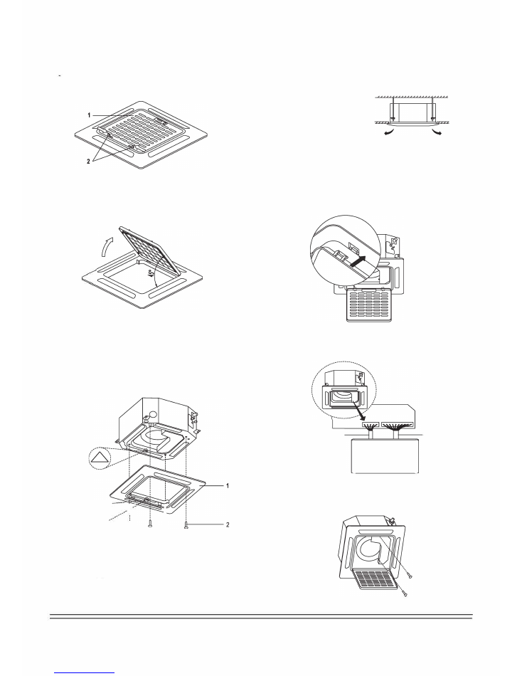
INSTALLATION OF THE DECORATION PANEL
.
Detach the intake grille.
Slide the 2 grille hooks toward the middle of the decoration
panel.
12
Intake Grille
Grille
H
ook
- Open the intake grille
at the angle shown below
and remove
it
.
.
Install the Decoration
P
anel
- Align the indicated" "on the decoration panel to the indicated
"
"
markings
on the unit
.
- Attach the decoration panel to the unit with the supplied screws
as shown in figure below.
---<'-----
乙 '
、、、、----
多心
一
』
.,R,斗;',',',':人
- After installing the decoration panel, ensure that there is no
space between the unit body and decoration panel. Otherwise,
air may leak through the gap and cause dewdrops.
(See figure below)
三
x
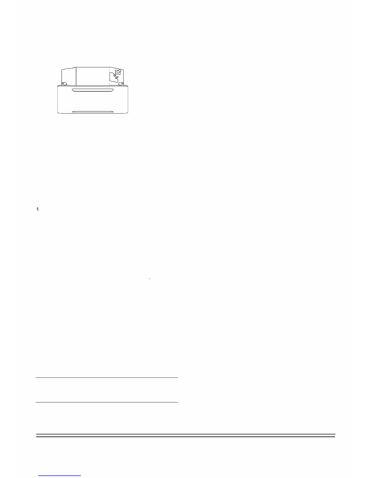
.
Mount the
I
ntake
G
rille.
Ensure that the buckles at the back of the grille be properly
seated in
to
the groove of the panel.
.
Connect the 2 wires of the decoration panel to the
mainboard of the unit.
5-core wire
X
言琶荨
10-core wire
.
Fasten the control box lid with 2 screws .
12
Decoration
P
anel
Screws (MS)(supplied with the panel)
15
.
Close the intake grille, and slide the 2 grille hooks back.
D[me]D
7
TEST OPERATION
Make sure the control box lids are closed on the indoor and outdoor
units.
Refer to "For the following items, take special care during construction
and check after installation is finished" on page 2.
After finishing the construction of refrigerant piping, drain piping, and
electric wiring, conduct a test operation accordingly to protect the unit.Test
operation after installing decoration panel
Open the gas side stop valve.
2 Open the liquid side stop valve.
3 Electrify
the
crank case heater for 6 hours.
4 Set to cooling operation with the remote controller, and start
operation by pushing
the
ON/OFF button.
5 Check the following points. If there is any malfunction, please
resolve it according to the chapter "Troubleshooting" in the
"Owner's Manual".
• The indoor unit
:
- Whether the switch on the remote controller works well.
- Whether the buttons on the remote controller work well
- Whether the air flow louver moves normally.
- Whether the room temperature is adjusted well.
- Whether the indicator lights up normally
- Whether the
temporary
buttons work well.
- Whether there is vibration o「abnormal noise during operation.
- Whether the drainage flows smoothly.
• The outdoor unit
:
- Whether there is vibration or abnormal noise during operation.
- Whether the gene
「
ated wind, noise, or condensed of by the air
conditioner have
generated excessive noise in
you「neighborhood.
- Whether any of the refrigerant is leaked
6 Turn off the main power supply after operation.
A
A protection feature prevents the air conditioner from being
activated for approximately 3 minutes when it is restarted
immediately after shut off.
16

is a registered trademark of Parker Davis HVAC International, Inc.
Parker Davis HVAC International, Inc.
2250 NW 102 Place, Doral, FL 33172 - USA
Tel
: (305) 513-4488
Fax
: (305) 513-4499
email :
info@pd-hvac.com
Website: www.pd-hvac.com
Copyright 2017, Parker Davis HVAC International, Inc., All rights reserved.