Full Text Searchable PDF User Manual
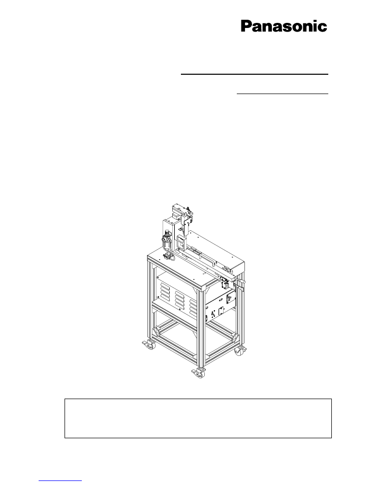
Intelligent Feeder Check Unit
Operating Instructions
Thank you for purchasing the intelligent feeder check unit.
Before placing the machine in service, be sure to read the instruction manual for
proper usage.
After that, store it carefully and read it if necessary.
EJW2A-E-OMAA-0001
Operation Manual
Model No.
NM-EJW2A
- 240 V
ŃĆ£
CN001P
PC-232CP
POWER
TEEE1394-6

3
ŌĆ£Use of this machine:
This machine is designed and constructed to be used for the maintenance of intelligent tape feeders.
This machine shall be used for this purpose only.
It shall not be used for any other purpose.ŌĆØ
ŌĆ£Operation of this machine:
This machine shall be operated by professional, specially trained operators.
Regarding the training course, please contact Panasonic Factory Solutions Co., Ltd. or PFSE.ŌĆØ
Machine was manufactured by: Panasonic Factory Solutions Co., Ltd.
441-13, Nagahasu, Tateishi-machi, Tosu-city, Saga, Japan
Phone number:
81-942-84-2644
Fax number:
81-942-84-2636
For Service and Supply of Spares in Europe
you may contact Panasonic Europe:
Continental Europe
PFSE
Panasonic Factory Solutions Europe
Winsbergring 15
22525 Hamburg
Germany
Phone number:
0049-(0)40-85386-321
Fax number:
0049-(0)40-85386-332
United Kingdom
PFSE
Panasonic Factory Solutions Europe
Panasonic House,Willoughby Road
Bracknell, Berks. RG12 8 FP
Phone number:
0044-(0)1344-853267
Fax number:
0044-(0)1344-425970
Year: 2006
EJW2A-E-OMA00-A01-01
4
Introduction
This manual describes how to handle the intelligent feeder check unit.
NOTICE
For information on how to operate the intelligent feeders and how to set them onto
the placement machine, refer to the Operation Manual for the tape feeders.
NOTICE
This manual describes how to handle the intelligent feeder check unit.
The following
pages refer to ŌĆ£intelligent feeder check unitŌĆØ as ŌĆ£check unitŌĆØ and ŌĆ£intelligent tape
feederŌĆØ as ŌĆ£ITF,ŌĆØ respectively.
EJW2A-E-OMA00-A01-00

5
= MEMO =
EJW2A-E-OMA00-A01-00

6
TABLE OF CONTENTS
Safety precautions ...................................................................................................... 9
Labels pasted on product for safety.......................................................................... 13
About storage management and handling................................................................ 15
1. INSTALLATION ..............................................1-1
1.1 Selecting Installation Location..............................................................................1-2
1.2 Transport ..............................................................................................................1-3
2. GENERAL DESCRIPTION..............................2-1
2.1 Specifications .......................................................................................................2-2
2.1.1 Basic Specifications .......................................................................................................................2-2
2.1.2 Hardware/OS Requirements...........................................................................................................2-2
2.2 Configurations ......................................................................................................2-3
2.3 Master Jig .............................................................................................................2-4
2.3.1 Illustration of Hole Locations...........................................................................................................2-4
2.4 Target ITF.............................................................................................................2-5
3. PREPARATIONS ............................................3-1
3.1 Checking Air Pressure..........................................................................................3-2
3.2 Adjusting Camera Position ...................................................................................3-3
3.2.1 Adjustment Procedure....................................................................................................................3-3
3.3 ITF Setting Procedure ..........................................................................................3-5
3.3.1 For ITF 8 mm Double Type.............................................................................................................3-5
3.3.2 For ITF 12/16 mm and 24/32 mm Types.........................................................................................3-6
3.4 Method for Connection .........................................................................................3-7
3.5 Supplying Power...................................................................................................3-8
4. SYSTEM SOFTWARE INSTALLATION..........4-1
4.1 Overview...............................................................................................................4-2
4.2 Installation Procedure...........................................................................................4-3
4.2.1 Main Menu.....................................................................................................................................4-4
4.2.2 Installing FireWire Converter Driver................................................................................................4-5
4.2.3 Installing Check Unit System Software .........................................................................................4-11
4.3 Uninstallation Procedure ....................................................................................4-15
EJW2A-E-OMA00-A02-00

7
5. ITF CHECKER................................................ 5-1
5.1 ITF Checker ..........................................................................................................5-2
5.1.1 Main Functions.............................................................................................................................. 5-2
5.1.2 Main Screen and Menus................................................................................................................ 5-2
5.1.3 Message Screens.......................................................................................................................... 5-4
5.1.4 Starting and Exiting ITF Checker ................................................................................................... 5-6
5.1.5 ITF System Standard Update ........................................................................................................ 5-7
5.1.6 Checking/Adjusting ITF Origin ....................................................................................................... 5-9
5.1.7 Adding/Removing/Modifying Component Data............................................................................. 5-20
5.1.8 Utility Functions........................................................................................................................... 5-22
5.1.9 Function to Check Free Space of System Software Installation Drive........................................... 5-24
6. ITF CHECK HISTORY MANAGE ................... 6-1
6.1 ITF Check History Manage ...................................................................................6-2
6.1.1 Main Functions.............................................................................................................................. 6-2
6.1.2 Main Screen and Menus................................................................................................................ 6-2
6.1.3 Reloading History Database .......................................................................................................... 6-4
6.1.4 Outputting History Data List to CSV............................................................................................... 6-4
6.1.5 Compressing History Data............................................................................................................. 6-5
6.1.6 Decompressing History Data ......................................................................................................... 6-5
6.1.7 Limiting Search for History Data .................................................................................................... 6-6
6.1.8 Deleting History Data..................................................................................................................... 6-6
6.1.9 Displaying History Data in Detail.................................................................................................... 6-7
7. MAINTENANCE ............................................. 7-1
7.1 Maintenance Items ...............................................................................................7-2
7.1.1 Daily Check Items ......................................................................................................................... 7-2
7.1.2 Periodic Check Items..................................................................................................................... 7-3
8. TROUBLESHOOTING.................................... 8-1
8.1 Troubleshooting ....................................................................................................8-2
8.2 Error Message ......................................................................................................8-7
8.2.1 Error Messages during Origin Check/Adjustment and on Update Failures...................................... 8-7
INDEX
APPENDIX 1. ORIGIN CHECK FLOW
APPENDIX 2. REINSTALLATION
EJW2A-E-OMA00-A02-00

8
= MEMO =
EJW2A-E-OMA00-A02-00
9
Safety precautions
Be sure to observe
The precautions that shall be observed in order to prevent an injury to the user or the
other persons, and damage to property, are described as follows.
The degrees of danger or injury, resulting from incorrect usage owing to failure to read an
indication, are classified and described as follows.
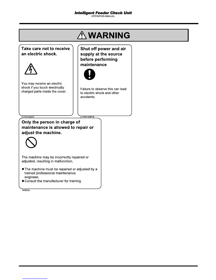
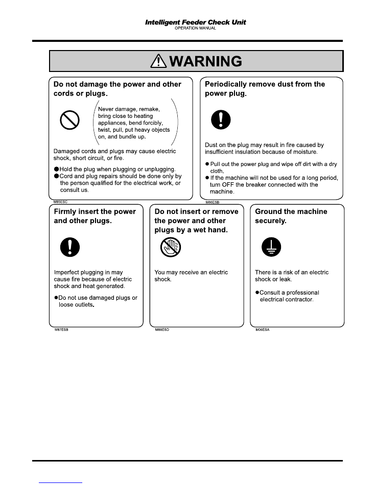
WARNING
This indication refers to a situation which is considered that there is a
possibility of death or serious injury.
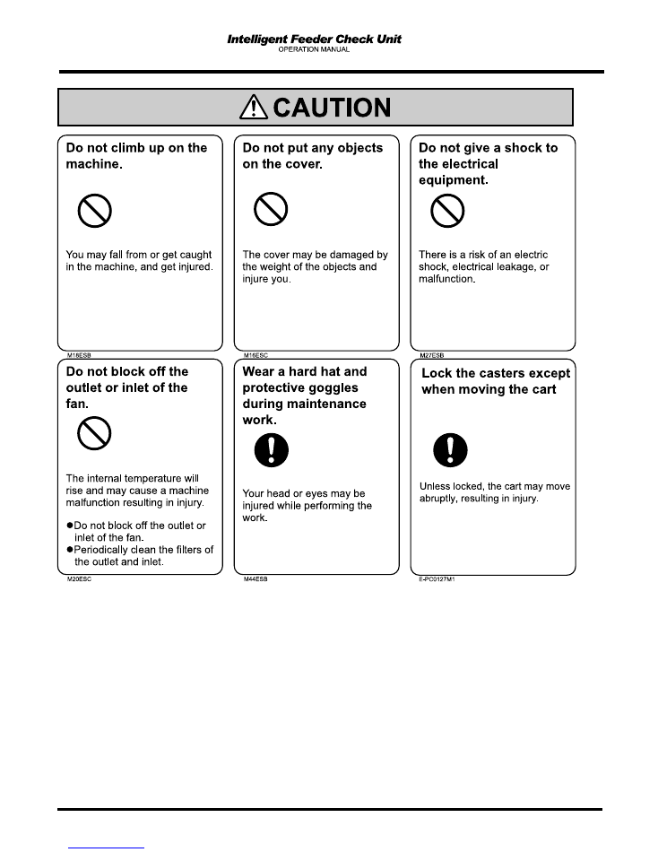
CAUTION
This indication refers to a situation which is considered that there is a
possibility of only injury or physical damage.
The matters that shall be observed are classified by the symbols shown below, and
described.
(The following are the examples of the symbols.)
This kind of symbol indicates the matters to which attention must be paid.
This kind of symbol indicates an action that must not be carried out.
This kind of symbol indicates an action that must be carried out.
EJW2A-E-OMA00-A03-00
10
EJW2A-E-OMA00-A03-00
11
EJW2A-E-OMA00-A03-00
12
EJW2A-E-OMA00-A03-00
13
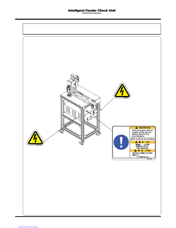
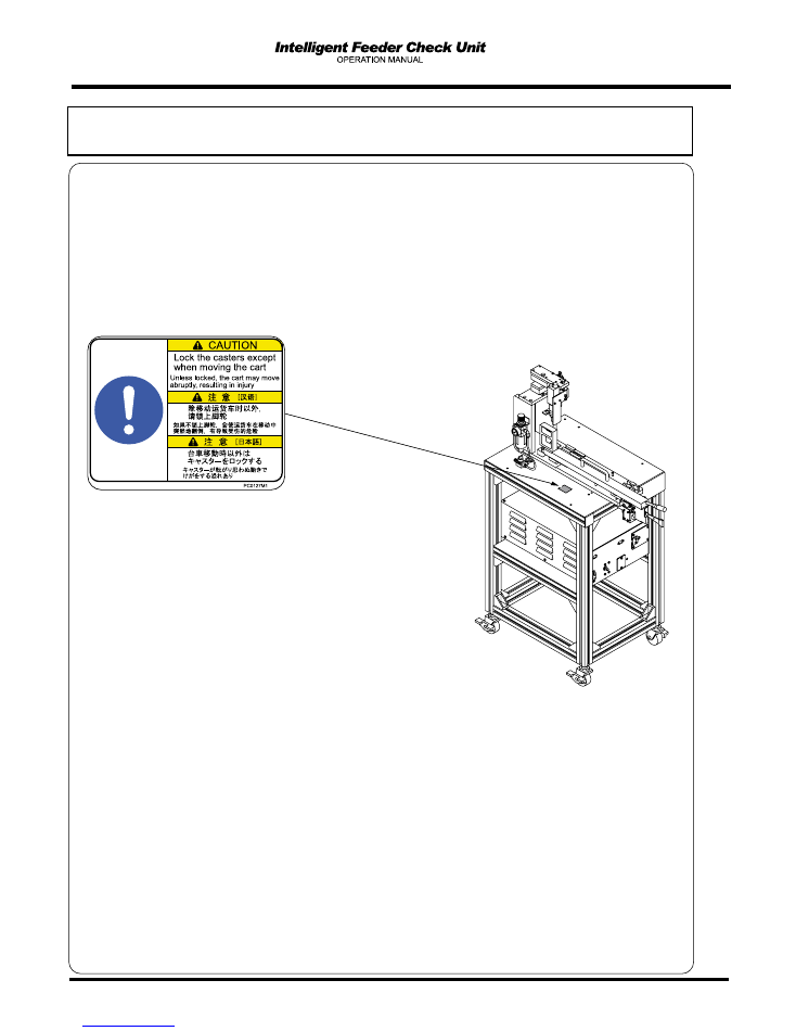
Labels pasted on product for safety
Warning labels
The warning labels are pasted on this machine as follows. Follow the instructions on each label.
If it has come off, place an order with us for it, referring to the Parts List; then, put a new one on a proper
location.
Warning label locations
EJW2A-E-OMA00-A04-00
- 240 V
ŌĆś
CN001P
PC-232CP
POWER
TEEE1394-6
EJW2A-010E
14
Labels pasted on product for safety
Caution labels
The warning labels are pasted on this machine as follows. Follow the instructions on each label.
If it has come off, place an order with us for it, referring to the Parts List; then, put a new one on a proper
location.
Warning label locations
EJW2A-E-OMA00-A04-00
- 240 V
ŌĆś
CN001P
PC-232CP
POWER
TEEE1394-6
EJW2A-011E
15
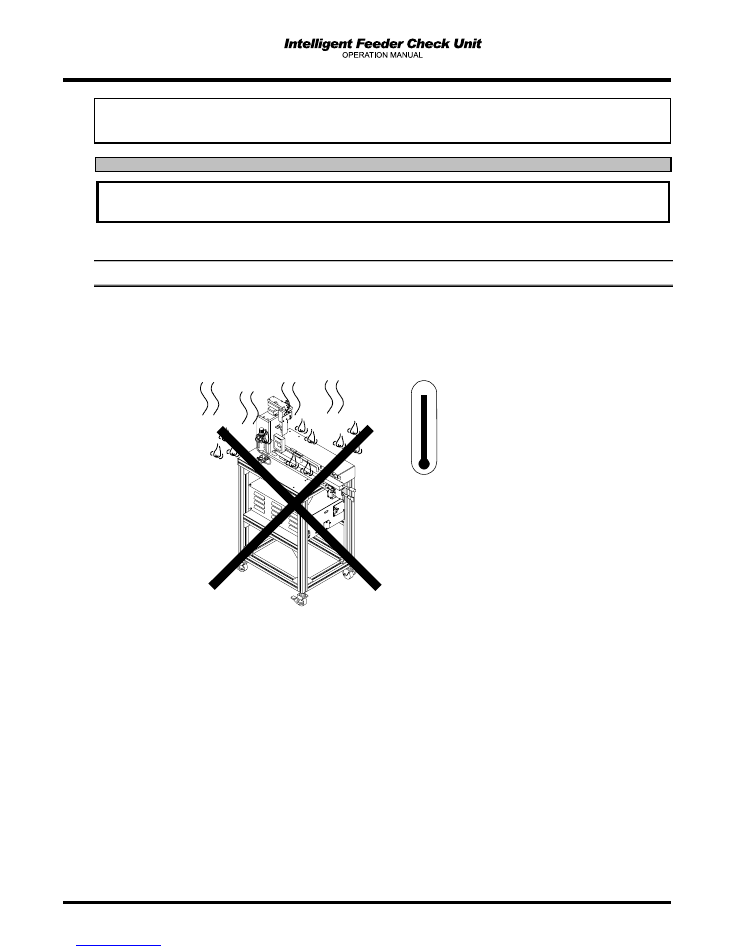
About storage management and handling
This describes the precautions in the storage of the check unit.
1
Storage Precautions
Avoid storing it in a high-temperature (40 degrees or over) and
high-humidity place or a low-temperature (0 degrees or below) place.
The formation of rust can cause such a trouble as faulty sliding.
NOTICE
In handling the check unit, be sure to observe the following matters.
- 240 V
ŌĆś
CN001P
PC-232CP
POWER
TEEE1394-6
EJW2A-AA
50
40
30
20
10
0
┬░┬░┬░┬░
C
EJW2A-E-OMA00-A04-00
16
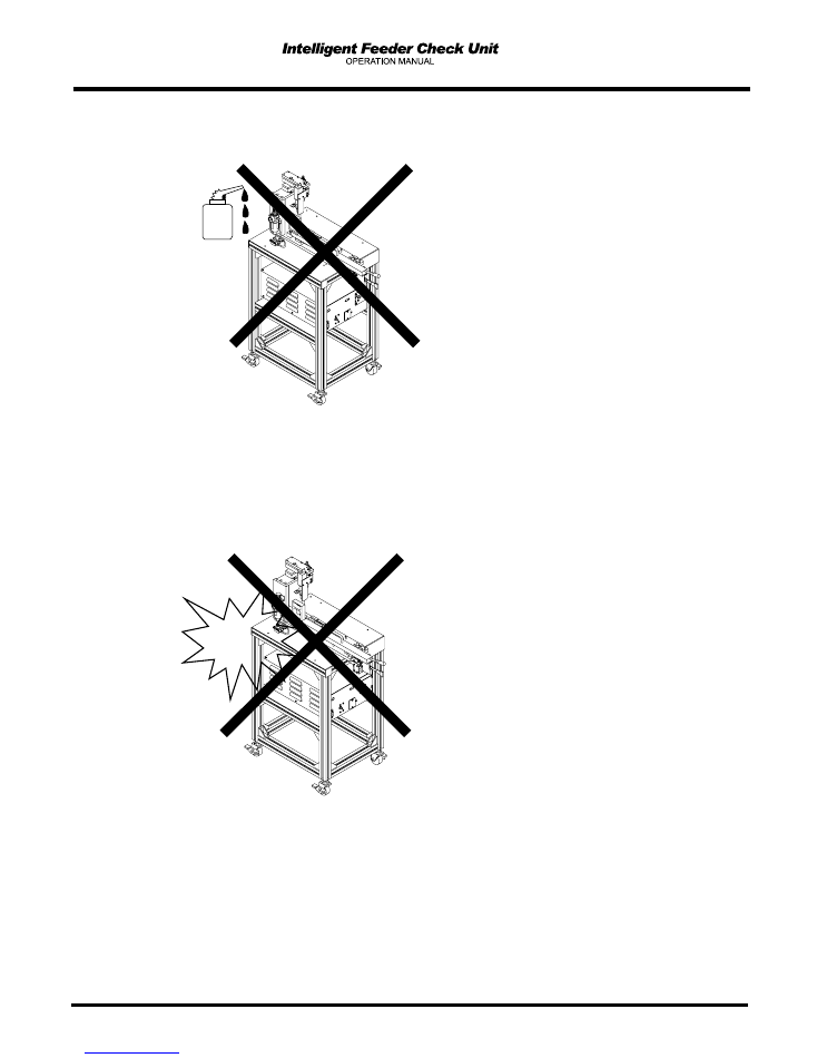
Avoid storing it in the place where oil or an organic solvent is splashed.
Otherwise, rubber and resin parts may potentially be deteriorated and broken.
Avoid bumping or knocking it down.
Even if there is no damage on the surface, actions can be affected.
- 240 V
ŌĆś
CN001P
PC-232CP
POWER
TEEE1394-6
EJW2A-AA
Oil
- 240 V
ŌĆś
CN001P
PC-232CP
POWER
TEEE1394-6
EJW2A-AA
EJW2A-E-OMA00-A04-00
17
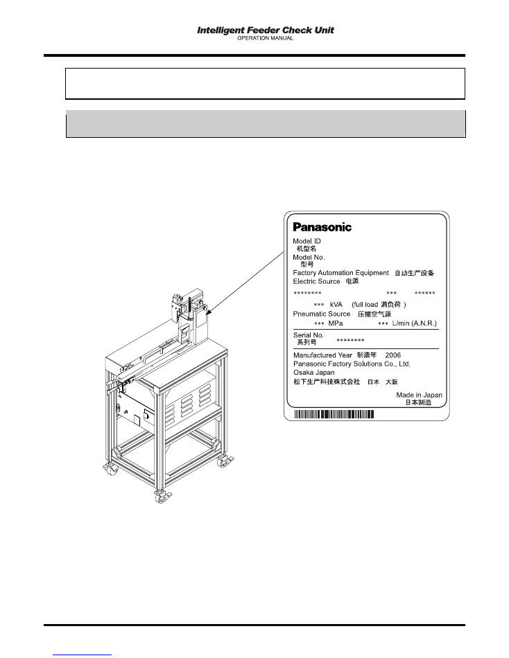
Serial plate
The serial plate indicating the product name (Model ID) and production number (Serial No.) of the machine
is pasted on the following location.
Actually,
ŌłŚ
is replaced with a numeric value.
EJW2A-E-OMA00-A04-01
EJW2A-AB
NM-EJW2A
NM-EJW2A

18
= MEMO =
EJW2A-E-OMA00-A04-00