Full Text Searchable PDF User Manual
CONTENTS
• PRODUCT SPECIFICATIONS ................................................................................................ 1
• DIMENSIONS .......................................................................................................................... 2
• WIRING DIAGRAM ............................................................................................................ 3 ~ 4
• REFRIGERATION CYCLE DIAGRAM..................................................................................... 5
• AIR CONDITIONER PERFORMANCE EVALUATION ............................................................ 5
• HOW TO INSTALL............................................................................................................. 6 ~ 7
• HOW TO OPERATE .......................................................................................................... 8 ~ 9
• TROUBLESHOOTING GUIDE .............................................................................................. 10
• CARE AND MAINTENANCE ................................................................................................. 11
• TECHNICAL DATA ............................................................................................................... 12
• EXPLODED VIEW ......................................................................................................... 13 ~ 14
• REPLACEMENT PARTS LIST .............................................................................................. 15
• ELECTRONIC CIRCUIT DIAGRAM ...................................................................................... 16
ORDER NO. MAC9604015C3
Panaso
nic
Panaso
nic
CW-C180BN
CW-A180BN
Service Manual
Room Air Conditioners
MODELS : CW-C180BN, CW-C240SN,
CW-A180BN, CW-A240SN.
© 1996 Matsushita Industrial Corp. Sdn. Bhd.
All rights reserved. Unauthorized copying and
distribution is a violation of law.
CW-C240SN
CW-A240SN
CW-C180BN
– 1 –
WARNING
This service information is designed for experienced repair technicians only and is not designed for use by the general
public. It does not contain warnings or cautions to advise non-technical individuals of potential dangers in attempting
to service a product. Products powered by electricity should be serviced or repaired only by experienced professional technicians.
Any attempt to service or repair the product or products dealt with in this service information by anyone else could result in serious injury
or death.
!
PRODUCT SPECIFICATIONS
MODELS
CW-C180BN
CW-C240SN
CW-A180BN
CW-A240SN
COOLING
HEATING
COOLING
HEATING
CAPACITY
(Btu/h)
17,900 – 17,700
22,700 – 22,510
15,690 – 15, 510
15,340 – 14,830
21,140 – 20,630
20,800 – 19,780
(W)
5,250 – 5,200
6,650 – 6,600
4,600 – 4,550
4,500 – 4,350
6,200 – 6,050
6,100 – 5,800
MOISTURE REMOVAL
(
s
/h)
2.9
4.0
2.5
––
3.4
––
(Pints/h)
6.1
8.5
5.3
7.2
AIR CIRCULATION
(m
3
/min)
14.0
17.0
14.0
16.0
(Cft/min)
490
600
490
560
COMPRESSOR OUTPUT
(W)
1,700
2,200
1,700
2,200
ELECTRICAL
Phase
Single
DATA
Cycle (Hz)
50
Voltage (V)
240 – 220
Running
Current (A)
11.6 – 11.2
15.2 – 15.4
11.7 – 11.0
9.9 – 8.9
14.8 – 14.6
13.6 – 12.8
Starting
Current (A)
50
60
50
60
Input (W)
2,360 – 2,230
3,100 – 3,050
2,450 – 2,300
1,950 – 1,700
3,150 – 3,050
2,800 – 2,650
CABINET
Height (mm)
16 – 7/8" (428)
16 – 7/8" (428)
16 – 7/8" (428)
16 – 7/8" (428)
DIMENSIONS
Width (mm)
26" (660)
26" (660)
26" (660)
26" (660)
Depth (mm)
25 – 7/32" (640)
28 – 3/4" (730)
25 – 7/32" (640)
28 – 3/4" (730)
NET WEIGHT
(kg)
59
72
59
74
(Ibs)
130
160
130
164
REFRIGERANT (R-22)
(g)
980
1,350
1,090
1,030
(oz)
34.6
47.7
38.5
36.4
NOISE LEVEL High
Indoor dB (A)
52 – 51
58 – 57
52 – 51
52 – 51
58 – 58
––
Outdoor dB (A)
60 - 59
67 – 66
60 – 59
61 – 60
68 – 69
––
Low
Indoor dB (A)
49 – 48
54 – 53
49 – 48
48 – 47
54 – 54
––
Outdoor dB (A)
56 – 55
66 – 63
57 – 56
59 – 58
65 – 65
––
* Specifications are subject to change without notice for further improvement.
All illustration shown inside caters for models CW-C180BN, CW-A180BN unless stated otherwise
CW-C180BN
– 2 –
Panasonic
Panasonic
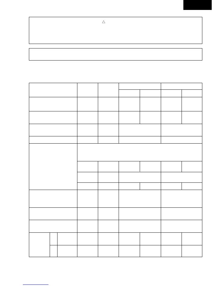
DIMENSIONS
CW-C180BN
CW-A180BN
CW-C240SN
CW-A240SN
FRONT VIEW
TOP VIEW
13-25/32"
(350)
J
N
SIDE VIEW
F
C
G
G
H
I
K
ITEM
CW-C240SN, CW-A240SN
A
Width
26"
(660)
B
Height
16 – 7/8"
(428)
C
Depth
28 – 25/32"
(730)
D
26 – 25/32"
(680)
E
1 – 31/32"
(50)
F
11 – 13/16"
(300)
G
2 – 3/64"
(75)
I
3/64"
(15)
J
10 – 13/16"
(288)
K
15 – 11/32" (389.6)
L
12 – 17/32"
(318)
M
3 – 5/32"
(80)
N
3 – 35/64"
(90)
ITEM
CW-C180BN, CW-A180BN
A
Width
26"
(660)
B
Height
16 – 7/8"
(428)
C
Depth
25 – 7/32"
(640)
D
23 – 7/32"
(590)
E
1 – 31/32"
(50)
F
10 – 15/16"
(220)
G
3 – 11/32"
(92)
H
3 – 1/32"
(77)
I
15 – 32"
(12)
J
10 – 15/16"
(278)
K
1 – 1/16"
(27)
L
12 – 17/32"
(318)
M
3 – 5/32"
(80)
N
3 – 35/64"
(90)
Unit : (mm)
Unit : (mm)
K
N
N
J
E
I
B
13-25/32"
(350)
2-3/32"
(53)
A
FRONT VIEW
SIDE VIEW
TOP VIEW
M
L
C
F
G
G
2-3/32"
(53)
M
L
A
E
D
D
B
CW-C180BN
– 3 –
CW-C180BN
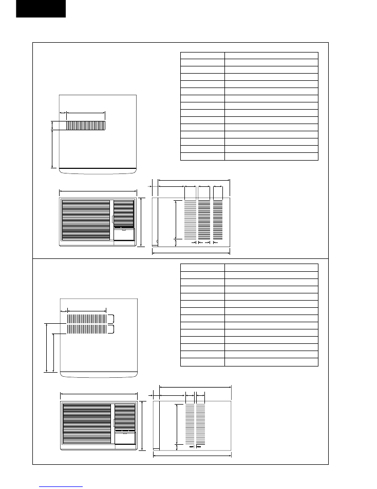
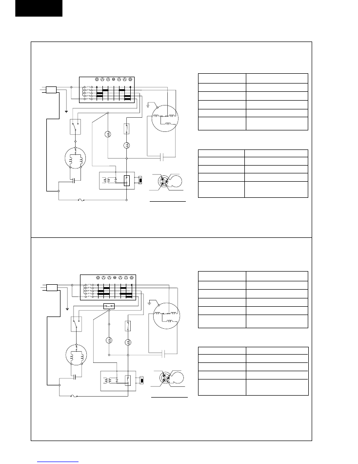
WIRING DIAGRAM
CW-C180BN
CW-C240SN
Connection
CWA92125
BLUE–YELLOW
18.8
Ω
YELLOW–ORANGE
6.25
Ω
RED–YELLOW
51.5
Ω
CWA31244
CAPACITOR
3µF, 400VAC
Resistance of Fan Motor windings and rated Capacitor
CW-C240SN
Connection
2JS442D4AA01
C-R
0.95
Ω
C-S
4.39
Ω
CAPACITOR
CWA31338
45µF, 370VAC
* Resistance at 20°C of Ambient Temp.
Resistance of Compressor windings and rated Capacitor
CW-C180BN
Connection
CWA95263
BLUE–YELLOW
47.9
Ω
YELLOW–ORANGE
25.2
Ω
RED–YELLOW
103.3
Ω
CWA31357
CAPACITOR
3.5µF, 450VAC
Resistance of Fan Motor windings and rated Capacitor
CW-C180BN
Connection
2JS350D6BA02
C-R
0.95
Ω
C-S
4.18
Ω
CAPACITOR
CWA31504
35µF, 370VAC
* Resistance at 20°C of Ambient Temp.
Resistance of Compressor windings and rated Capacitor
P O W E R S U P P L Y C O R D
P O W E R S U P P L Y C O R D
1 ø , 2 4 0 – 2 2 0 V , 5 0 H z
1 ø , 2 4 0 – 2 2 0 V , 5 0 H z
C A P A C I T O R
C A P A C I T O R
M A I N S W I T C H
M A I N S W I T C H
BROWN
BROWN
1
0
2
3
AIR SWING
AIR SWING
SELECT SWITCH
SELECT SWITCH
AIR SWING MOTOR
AIR SWING MOTOR
BLUEBLUE
BLUEBLUE
BLUEBLUE
BLUEBLUE
REDRED
REDRED
WHITEWHITE
BLACK
BLACK
WHITE
WHITE
WHITE
WHITE
YELLOW
YELLOW
YELLOW/GREEN
YELLOW/GREEN
YELLOW/GREENYELLOW/GREEN
YELLOW
YELLOW
BLUE
BLUE
BLUE
BLUE
BLACK
BLACK
ORANGE
ORANGE
1
2
R
S
C
FAN MOTORFAN MOTOR
C O M P R E S S O R
C O M P R E S S O R
THERMOSTATTHERMOSTAT
RED (RED)
RED (RED)
BLUE (BLU)
BLUE (BLU)
YELLOW (YEL)
YELLOW (YEL)
TRADE MARK
TRADE MARK
T H E P A R E N T H E S I Z E D L E T T E R I S
I N D I C A T E D O N T E R M I N A L C O V E R .
I N D I C A T E D O N T E R M I N A L C O V E R .
C O M P R E S S O R T E R M I N A L
C O M P R E S S O R T E R M I N A L
FUSE (5A)
FUSE (5A)
P
1
CAPACITORCAPACITOR
LOW
LOW
FAN
FAN
HIGH
HIGH
FAN
FAN
HIGH
HIGH
COOL
COOL
LOW
LOW
COOL
COOL
OFF
OFF
P O W E R S U P P L Y C O R D
P O W E R S U P P L Y C O R D
1 ø , 2 4 0 – 2 2 0 V , 5 0 H z
1 ø , 2 4 0 – 2 2 0 V , 5 0 H z
C A P A C I T O R
C A P A C I T O R
CAPACITORCAPACITOR
M A I N S W I T C H
M A I N S W I T C H
BROWN
BROWN
1
0
2
3
AIR SWING
AIR SWING
SELECT SWITCH
SELECT SWITCH
AIR SWING MOTOR
AIR SWING MOTOR
BLUEBLUE
YELLOW/GREENYELLOW/GREEN
BLUEBLUE
BLUEBLUE
BLUEBLUE
REDRED
REDRED
WHITEWHITE
WHITEWHITE
BLACK
BLACK
WHITE
WHITE
WHITE
WHITE
YELLOW
YELLOW
YELLOW/GREEN
YELLOW/GREEN
YELLOW
YELLOW
BLUE
BLUE
BLUE
BLUE
BLACK
BLACK
ORANGE
ORANGE
1
2
R
S
C
FAN MOTORFAN MOTOR
C O M P R E S S O R
C O M P R E S S O R
THERMOSTATTHERMOSTAT
(TEMP. CONTROL)(TEMP.
CONTROL)
THERMOSTATTHERMOSTAT
(LOW TEMP.)(LOW
TEMP.)
RED (RED)
RED (RED)
BLUE (BLU)
BLUE (BLU)
YELLOW (YEL)
YELLOW (YEL)
TRADE MARK
TRADE MARK
T H E P A R E N T H E S I Z E D L E T T E R I S
T H E P A R E N T H E S I Z E D L E T T E R I S
I N D I C A T E D O N T E R M I N A L C O V E R .
I N D I C A T E D O N T E R M I N A L C O V E R .
C O M P R E S S O R T E R M I N A L
C O M P R E S S O R T E R M I N A L
FUSE (5A)
FUSE (5A)
P
1
LOW
LOW
FAN
FAN
HIGH
HIGH
FAN
FAN
HIGH
HIGH
COOL
COOL
LOW
LOW
COOL
COOL
OFF
OFF
CW-C240SN
CW-C180BN
– 4 –
RED (RED)
RED (RED)
BLUE (BLU)
BLUE (BLU)
YELLOW (YEL)
YELLOW (YEL)
TRADE MARK
TRADE MARK
T H E P A R E N T H E S I Z E D L E T T E R I S
I N D I C A T E D O N T E R M I N A L C O V E R .
I N D I C A T E D O N T E R M I N A L C O V E R .
C O M P R E S S O R T E R M I N A L
C O M P R E S S O R T E R M I N A L
P O W E R S U P P L Y C O R D
P O W E R S U P P L Y C O R D
1 ø , 2 4 0 – 2 2 0 V , 5 0 H z
1 ø , 2 4 0 – 2 2 0 V , 5 0 H z
M A I N S W I T C H
M A I N S W I T C H
BROWN
BROWN
BROWN
BROWN
BLACK
BLACK
BLACK
BLACK
YELLOW
YELLOW
YELLOW/GREENYELLOW/GREEN
BLACKBLACK
BLACKBLACK
BLUE
BLUEBLUE
BLUEBLUE
BLUEBLUE
BLACK
REDRED
REDRED
YELLOW
YELLOW
YELLOW/GREEN
YELLOW/GREEN
ORANGE
ORANGE
1
0
2
3
AIR SWING AIR SWING
SELECT SELECT
SWITCHSWITCH
AIR SWING AIR SWING
MOTORMOTOR
BLACK
BLACK
BLUE
BLUE
BLUE
BLUE
BLUE
BLUE
RED
RED
BLUE
BLUE
BLUE
BLUE
RED
RED
RED
RED
GRAY
GRAY
GRAY
GRAY
FAN
FAN
MOTOR
MOTOR
FUSE
FUSE
(5A)
(5A)
4
2
B
A
H
C
L
C A P A C I T O R
C A P A C I T O R
C A P A C I T O R
C A P A C I T O R
C O M P R E S S O R
C O M P R E S S O R
T H E R M O S T A T
T H E R M O S T A T
COIL-REVERSING COIL-REVERSING
VALVEVALVE
E L E C T R I C D E I C E R
E L E C T R I C D E I C E R
1
2
5
1
P
3
4
6
Z N R
R y – D
R y – D
R
C
S
N C
C O M
OFF
OFF
LOW
LOW
HIGH
HIGH
HIGH
HIGH
COOL
COOL
HEAT
HEAT
LOW
LOW
FAN
FAN
FAN
FAN
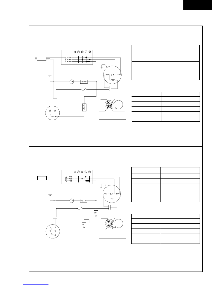
CW-A180BN
Connection
CWA95263
BLUE–YELLOW
47.9
Ω
YELLOW–ORANGE
25.2
Ω
RED–YELLOW
103.3
Ω
CWA31357
CAPACITOR
3.5µF, 450VAC
CW-A180BN
Connection
2JS356D6DA01
C-R
0.86
Ω
C-S
3.45
Ω
CAPACITOR
CWA31506
45µF, 370VAC
* Resistance at 20°C of Ambient Temp.
Resistance of Fan Motor windings and rated Capacitor
Resistance of Compressor windings and rated Capacitor
CW-A240SN
Connection
CWA92125
BLUE–YELLOW
18.8
Ω
YELLOW–ORANGE
6.3
Ω
RED–YELLOW
51.5
Ω
CWA31244
CAPACITOR
3µF, 400VAC
CW-A240SN
Connection
2JS442D4AA01
C-R
0.95
Ω
C-S
4.39
Ω
CAPACITOR
CWA31506
45µF, 370VAC
* Resistance at 20°C of Ambient Temp.
Resistance of Fan Motor windings and rated Capacitor
Resistance of Compressor windings and rated Capacitor
CW-A180BN
CW-A240SN
RED (RED)
BLUE (BLU)
YELLOW (YEL)
TRADE MARK
T H E P A R E N T H E S I Z E D L E T T E R I S
T H E P A R E N T H E S I Z E D L E T T E R I S
I N D I C A T E D O N T E R M I N A L C O V E R .
I N D I C A T E D O N T E R M I N A L C O V E R .
C O M P R E S S O R T E R M I N A L
P O W E R S U P P L Y C O R D
P O W E R
S U P P L Y
C O R D
1 ø , 2 4 0 – 2 2 0 V , 5 0 H z
1 ø ,
2 4 0 – 2 2 0 V ,
5 0 H z
M A I N S W I T C H
M A I N
S W I T C H
BROWN
BROWN
BROWN
BROWN
BLACK
BLACK
BLACK
BLACK
BLACK
BLACK
BLACK
YELLOW
BLUE
BLUE
YELLOW/GREEN
BLUE
BLACK
RED
RED
YELLOW
YELLOW
YELLOW/GREEN
YELLOW/GREEN
ORANGE
ORANGE
1
0
2
3
AIR SWING
SELECT
SWITCH
AIR SWING
MOTOR
BLACK
BLACK
BLUE
BLUE
BLUE
BLUE
BLUE
RED
RED
BLUE
BLUE
BLUE
BLUE
RED
RED
RED
RED
GRAY
GRAY
GRAY
GRAY
BLACK
BLACK
FAN
FAN
MOTOR
MOTOR
FUSE (5A)
4
2
B
A
H
C
L
C A P A C I T O R
C A P A C I T O R
T H E R M O S T A T
T H E R M O S T A T
C A P A C I T O R
C A P A C I T O R
C O M P R E S S O R
C O M P R E S S O R
T H E R M O S T A T
T H E R M O S T A T
COIL-REVERSING
COIL-REVERSING
VALVE
E L E C T R I C D E I C E R
E L E C T R I C D E I C E R
4
4
1
1
P
3
2
S 2
S 2
S 1
S 1
Z N R
Z N R
R y – D
R y – D
R
C
S
N C
N C
C O M
C O M
OFF
OFF
LOW
LOW
HIGH
HIGH
HIGH
HIGH
COOL
COOL
HEAT
HEAT
LOW
LOW
FAN
FAN
FAN
FAN
CW-C180BN
– 5 –
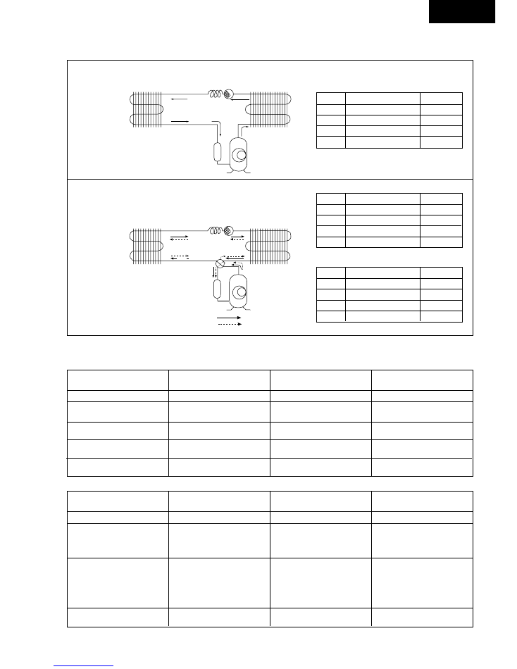
REFRIGERATION CYCLE DIAGRAM
2
6
B
C
A
5
D
CW-A180BN
CW-A240SN
ITEM
PRESSURE (kg/cm
2
)
TEMP. (°C)
A
15.5 ~ 19.0
55 ~ 70
B
4.0 ~ 4.5
0 ~ 5
C
15.0 ~ 18.5
37 ~ 47
D
15.4 ~ 18.9
45 ~ 55
* Indoor temp. at 21°C (DB), and Outdoor at 7°C (DB), 6°C (WB).
ITEM
PRESSURE (kg/cm
2
)
TEMP. (°C)
A
17.5 ~ 21.0
75 ~ 90
B
17.2 ~ 20.7
38 ~ 45
C
5.5 ~ 6.1
7 ~ 15
D
5.3 ~ 5.8
5 ~ 15
* Indoor temp. at 27°C (DB), 19°C (WB) and Outdoor at 35°C , 24°C.
1
4
3
SUCTION & DISCHARGE AIR
CURRENT
DETERMINATION
REMEDY
TEMPERATURE DIFFERENCE
12°C and over
As specified
• Nothing wrong
• None
12°C and over
Higher than specified
• Nothing wrong, outdoor temperature
• None
is high
• Something is preventing heat
• Clean air-filter
radiation at indoor heat-exchanger
Under 12°C
Lower than specified
• Nothing wrong, outdoor temperature
• None
is too low
• Something is preventing heat
• Improve heat radiation at outdoor
radiation at outdoor heat-exchanger
heat-exchanger
• Leakage of refrigerant
• Locate & repair leak
• Refrigerant system is blocked
• Flush refrigeration leak
Under 12°C
Higher than 150% of specified
• Compressor defect
• Replace compressor
• Compressor capacitor defect
• Replace compressor capacitor
1
Compressor
2
4-Way Valve
3
Evaporator
4
Capillary Tube
5
Strainer
6
Condenser
7
Accumulator
HEATING
COOLING
ITEM
PRESSURE (kg/cm
2
)
TEMP. (°C)
A
18.5 ~ 22.0
80 ~ 95
B
18.2 ~ 21.7
44 ~ 52
C
5.7 ~ 6.3
7 ~ 15
D
5.5 ~ 6.0
6 ~ 16
1
Compressor
2
Condenser
3
Strainer
4
Capillary Tube
5
Evaporator
6
Accumulator
CW-C180BN
CW-C240SN
3
4
2
7
6
C
A
1
B
5
D
HEATING
COOLING
* Note: Room air humidity is relatively higher, the Temp. difference will be smaller.
* Indoor temp. at 27°C (DB), 19°C (WB) and Outdoor at 35°C , 24°C.
SUCTION & DISCHARGE AIR
CURRENT
DETERMINATION
REMEDY
TEMPERATURE DIFFERENCE
8°C and over
As specified
Nothing wrong
• None
8°C and over
Higher than specified
Nothing wrong, outdoor temperature is
• Improve heat radiation
too high, heat radiation is not efficient
Under 8°C
Higher than specified but below
Something is preventing heat radiation
• Excessive amount of refrigerant
150% of specified
• Improve heat radiation
Under 8°C
Lower than specified
Leakage of refrigerant or refrigerant
• Locate repair leak
system is blocked
• Flush refrigeration cycle
Under 8°C
Higher than 150% of specified
Compressor defect or compressor
• Replace the compressor or
capacitor defect
compressor capacitor
HEATING
AIR CONDITIONER PERFORMANCE EVALUATION
COOLING
CW-C180BN
– 6 –
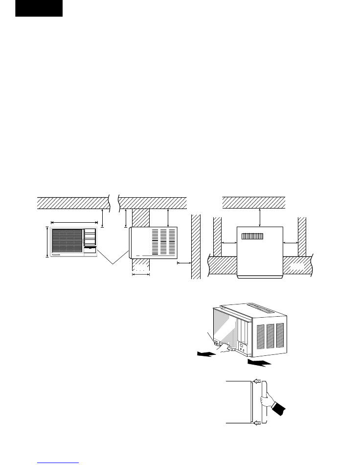
Over
15 cm
Over
15 cm
66 cm
43 cm
Front Grille
Less than
22 cm
Outdoor
(wall)
Over
50 cm
Fence or
likewise
Indoor
Ceiling
(TOP VIEW)
Outdoor
Over
15 cm
Over 50 cm
Over
15 cm
Indoor
(wall)
Fence or
likewise
(SIDE VIEW)
(FRONT VIEW)
Please read the following before installing the Air Conditioner.
Select the best location for the most efficient cooling.
Location
• The air conditioner should be installed in a dry place where there are no draughts.
• Condensation from the air conditioner must be drained to an appropriate location.
• Do not install in a location where flammable gas leaks are a possibility.
• Using in locations where the air is salty such as beside the sea or near hot spas, or
where sulphurous gas is generated, may lead to a malfunction. Please consult your dealer.
• Select a installation location which is rigid and strong enough to support or hold the unit and select a
location for easy maintenance.
How to install
• There should not be any obstacles surrounding the unit.
• Prepare the installation hole slightly bigger than cabinet size.
1) PREPARE CHASSIS
• Remove chassis locking bracket by loosening the screw.
• Slide the chassis out from the cabinet.
2) Place cabinet into opening and secure it by wood screws or
nails.
• The cabinet should be installed tilted slightly lower to the
rear for necessary condensate drainage. (Max. 10mm).
3) Slide Chassis into the cabinet which installed the above 2.
• The tubings or ducting part should not touch the cabinet
4) Lock the chassis into cabinet by chassis locking bracket.
5) Place FRONT GRILLE onto CABINET by screws.
• To place the grille, hook top of grille onto top of cabinet, push
bottom of grille in until it snaps into place. Secure the Front Grille
with the screws at the right, left and center of the grille.
Grille
Cabinet
To place the Grille
Chassis
Locking
Bracket
HOW TO INSTALL
CW-C180BN
– 7 –
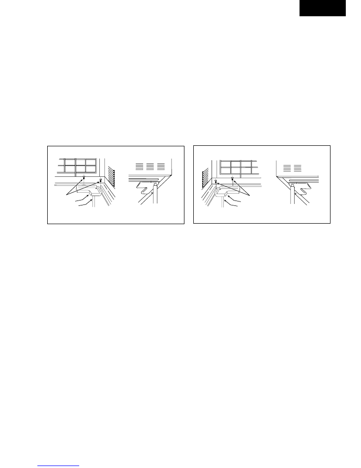
HOW TO INSTALL
3. Drain Water....
To get the maximum cooling efficiency this air conditioner is designed to splash the condensate on the condenser coil.
This method is called “Slinger-Up System”. (For cooling model only)
If the splashing sound annoys you, you can provide an outside drain by using the following procedure which may, however cause
a small loss of performance.
1. Slide out the chassis from the cabinet.
2. Remove the rubber plug from the body base plate. (For cooling model only)
3. Install the drain pan prepared in the accessory kit to the corner of the cabinet with 2 screws.
4. Connect the drain hose to the outlet on the drain pan bottom.
5. Slide the chassis into its original place in the cabinet.
Note: Drain hose or tubing can be purchased locally to satisfy your particular needs.
4. Plug line cord into wall receptacle.
<240–220V, 50Hz>
•
Power should be from independent circuit.
•
Nominal cross sectional area of power supply wire must be 3 core x 2.5 mm
2
or above.
EXTERNAL VIEW
INTERNAL VIEW
SCREWS
DRAIN PAN
DRAIN HOSE
Install drain pan at left corner of cabinet.
EXTERNAL VIEW
INTERNAL VIEW
Install drain pan at right corner of cabinet.
SCREWS
(CW-C180BN, CW-A180BN)
(CW-C240SN, CW-A240SN)
DRAIN PAN
DRAIN HOSE
CW-C180BN
– 8 –
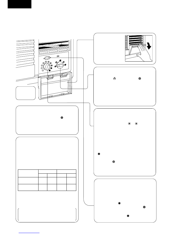
°
C
1
. Power Supply
Set the Main Control Knob to the “ ” OFF
position; confirm that the power supply cord is
connected to a proper AC outlet.
Recommended
Use the air conditioner under
the following conditions:
• Operating temperature range.
(unit in °C)
Indoor unit
Outdoor unit
D.B.T. W.B.T. D.B.T. W.B.T.
Maximum
Temperature
Minimum
Temperature
D.B.T.: Dry Bulb Temperature
W.B.T.: Wet Bulb Temperature
• Humidity does not exceed 90%.
Continuous operation at over 90% humidity
may create condensation and waterdrops on
the intake and outlet vents.
32
23
43
26
21
15
21
15
Illustration
only for
CW-C180BN
2
. Open the
cover
3
. Main Control Knob
Set to either “
” LOW COOL or “
” HIGH
COOL as required.
(FAN setting operates the fan only.)
* Caution: If the Main Control Knob is turned
off or changed to a fan setting from a cooling
operation setting, WAIT at least 3 minutes
before resetting to a cooling operation.
4
. Thermostat Control Knob
Set the Thermostat Control Knob at the
desired setting. (Usually “ ~ ” is a
recommended setting position.) If the room
temperature is unsatisfactory after a
reasonable amount of time, turn the control
knob clockwise to cool the room more, or
anticlockwise to cool the room less.
• When the Thermostat Control Knob is set to
“ ”, moisture may freeze onto the coils and
prevent effective cooling. If this happens, turn
the knob to “
” HIGH FAN, and the thermostat
control knob anticlockwise. This will quickly
defrost the cooling coil so that normal cooling
can be resumed.
5
. Air Swing Switch
(Airflow direction adjustment
Side-to-Side)
For fixed side-to-side air direction, set the Air
Swing Switch to “ ” ON until the desired air
direction is obtained, then move it to “ ” OFF.
For continuous side-to-side air circulation, set
the Air Swing Switch to “ ” ON and leave it
there.
HOW TO OPERATE
CW-C180BN, CW-C240SN (Cooling Only)
CW-C180BN
– 9 –
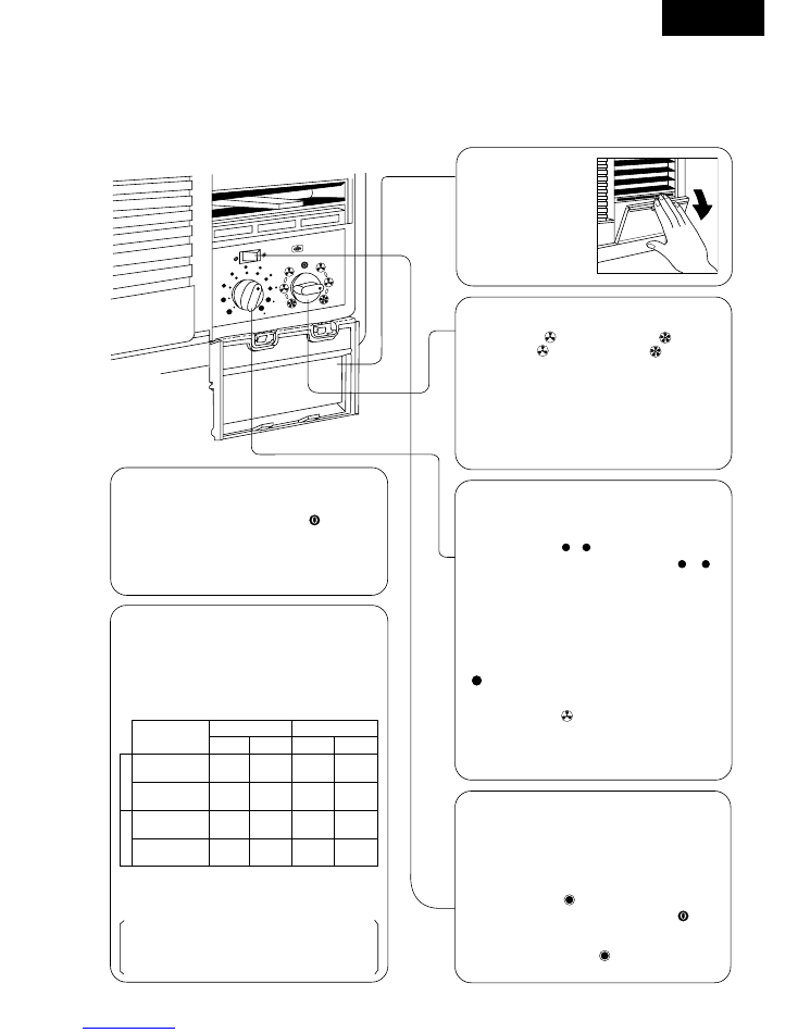
°
C
1
. Power Supply
Set the Main Control Knob to the “ ” OFF
position; confirm that the power supply cord is
connected to a proper AC outlet.
32
23
43
26
21
15
21
15
Recommended
Use the air conditioner under
the following conditions:
• Operating temperature range.
(unit in °C)
Indoor unit
Outdoor unit
D.B.T. W.B.T. D.B.T. W.B.T.
Maximum
Temperature
Minimum
Temperature
Maximum
Temperature
Minimum
Temperature
D.B.T.: Dry Bulb Temperature
W.B.T.: Wet Bulb Temperature
• Humidity does not exceed 90%.
Continuous operation at over 90% humidity
may create condensation and waterdrops on
the intake and outlet vents.
HEATING
COOLING
27
–
21
15
20
–
-5
-6
2
. Open the
cover
3
. Main Control Knob
Set to either “
” LOW COOL or “
” HIGH
COOL and “
” LOW HEAT or “
” HIGH
HEAT as required.
(FAN setting operates the fan only.)
* Caution: If the Main Control Knob is turned
off or changed to a fan setting from a cooling
or heating operation setting, WAIT at least 3
minutes before resetting to a cooling or
heating operation.
4
. Thermostat Control Knob
Set the Thermostat Control Knob to the desired
setting. (Usually “ ~ ” (Red) is a
recommended setting for heating and “ ~ ”
(Blue) for cooling.) If the room temperature is
unsatisfactory after a reasonable amount of
time, turn the control knob clockwise or anti-
clockwise to make the room cooler or warmer.
• When the Thermostat Control Knob is set to
“
” (Blue), moisture may freeze onto the coils
and prevent effective cooling. If this happens,
turn the knob to “ ” (Gray) FAN, and the
thermostat control knob anticlockwise. This will
quickly defrost the cooling coil so that normal
cooling can be resumed.
5
. Air Swing Switch
(Airflow direction adjustment
Side-to-Side)
For fixed side-to-side air direction, set the Air
Swing Switch to “
” ON until the desired air
direction is obtained, then move it to “
” OFF.
For continuous side-to-side air circulation, set
the Air Swing Switch to “
” ON and leave it
there.
HOW TO OPERATE
CW-A180BN, CW-A240SN (Cooling & Heating)
CW-C180BN
– 10 –
TROUBLE
CHECK
RESULT
CAUSE
REMEDY
Fan Motor and
1. Supply Voltage.
Less than - 10% by Rated.
Customer Restarted unit
Consult ELECTRICIAN.
Compressor
2. Fuse Box or Circuit Breaker.
Open Contacts.
immediately without
Repair Open Circuit.
won’t run.
waiting 3 minutes
WAIT FOR 3 MINUTES.
3. Power cord or Wiring Harness.
Pulled loose or Shorted.
Repair or Replace it.
4. Thermostat Setting.
Higher than ROOM TEMP.
Set it LOWER.
Fan Motor
1. Objects around Fan.
Locked Fan.
Fan Hitting Cowling or
Adjust Fan Position set screw.
won’t run
Foreign Materials.
Remove Foreign Materials.
Frozen Bearings.
Replace Fan Motor.
2. RESISTANCE between Wires.
Shorted/Open circuit.
Shorted or Burned out.
Replace Fan Motor.
3. Capacitor Fan Motor.
OHM Meter doesn’t Deflect.
Capacitor Defect.
Replace Capacitor Fan.
4. Main Control Switch.
No contacts at Position Shown.
Main Control Switch defect.
Replace Main Control Switch.
Compressor
1. Thermostat Setting.
Higher than ROOM TEMP.
Set it lower.
won’t run
2. RESISTANCE between
Shorted.
Winding Coil touched to the
Replace Compressor.
(Fan runs)
Terminal and the
Body.
Compressor Body.
3. RESISTANCE between
Shorted.
Rear Shorted or Burnt out.
Replace Compressor.
Terminals.
4. Overload Protector.
Infinity between Terminals.
Overload protector defect.
Replace Overload Protector.
5. Capacitor Compressor.
OHM Meter doesn’t deflect.
Capacitor defect.
Replace Capacitor Comp.
6. Thermostat.
No CLICK around position.
Thermostat defect.
Replace Thermostat.
7. Main Control Switch.
No contacts at Position shown.
Main Control Switch defect.
Replace Main Control Switch.
Insufficient
1. Thermostat Setting.
Higher or lower than ROOM TEMP.
Set it lower or higher.
cooling or
2. Ventilation Door open.
Open.
Reduces capacity.
Close Vent door.
heating
3. Air Filter dirty.
Clogged or Dirty.
Restricted air circulation.
Clean or Replace Air Filter.
4. Location of installation.
Sunlight hitting outdoor side
Restricted Heat Exchanger
Consider building an AWNING.
at cooling.
Obstacles.
Restricted Heat Exchanger.
Remove obstacles or
reinstall unit.
5. Evaporator/Condenser
Clogged or Dirty.
Restricted air circulation.
Clean by steam cleaner.
Coil obstructed.
6. Unit capacity for the room too
Not Satisfied.
Replace the Unit with
small.
bigger one.
7. Temp difference and
REFER PERFORMANCE
Leakage of refrigerant or
Locate repair leak.
Running Current.
EVALUATION.
refrigeration system is blocked.
Flush refrigeration cycle.
Noise
1. Source of Noise.
Vibration.
Faulty installation.
Reinstall unit or Reinforce
the installation.
Intermittent Noise.
Fan hitting objects.
Adjust Fan position or
remove Foreign Materials.
Refrigerant tubing touching
About 1/2" Clearance.
each other.
Fan splashing Drain Water.
Consider Attaching the Drain
Pan and pull plug in bottom
pan. (REFER INSTALLATION
INSTRUCTIONS)
No heating
1. Reversing Valve Coil.
Infinity between Coil.
Replace Reversing Valve coil.
(Fan and
2. Reversing Valve.
Resistance between Reversing
Replace Reversing Valve.
Compressor run.)
Valve Coil.
Water dripping
1. Unit Installation.
Tilted to inside room.
Restricted run off.
Tilt unit to outside slightly.
inside room
2. Drain Tray-STYROFOAM
Clogged.
Clogged or blocked.
Remove the foreign materials.
Pieces blocking Drain
(REFER OPERATING
Channel.
INSTRUCTIONS)
Frozen
1. Thermostat Setting
Set too low for ambient
Outdoor TEMP. Low
Set Main Control Switch to
Evaporator
conditions.
(Night time)
Fan to melt ICE and Set the Temp.
control to higher temperature
2. Air Filter/Evaporator.
Clogged or Dirty.
Restricted air circulation
Clean Air Filter/Evaporator.
3. Temp. difference and
REFER PERFORMANCE
Leakage of refrigerant or
Locate repair leak.
Running Current.
EVALUATION.
refrigeration system is blocked.
Flush refrigeration cycle.
Frozen
1. Outdoor ambient
Heating Operation at Low
Outdoor ambient temp.
Set Main Control Switch
Condenser
temp.
outdoor ambient temp.
is Low.
to Fan to melt ICE.
TROUBLESHOOTING GUIDE
WARNING: DISCONNECT UNIT FROM ELECTRICAL POWER SUPPLY BEFORE MAKING ANY ELECTRICAL
CHECKS.
DISCHARGE THE CAPACITOR BEFORE CHECKING IT.
CW-C180BN
– 11 –
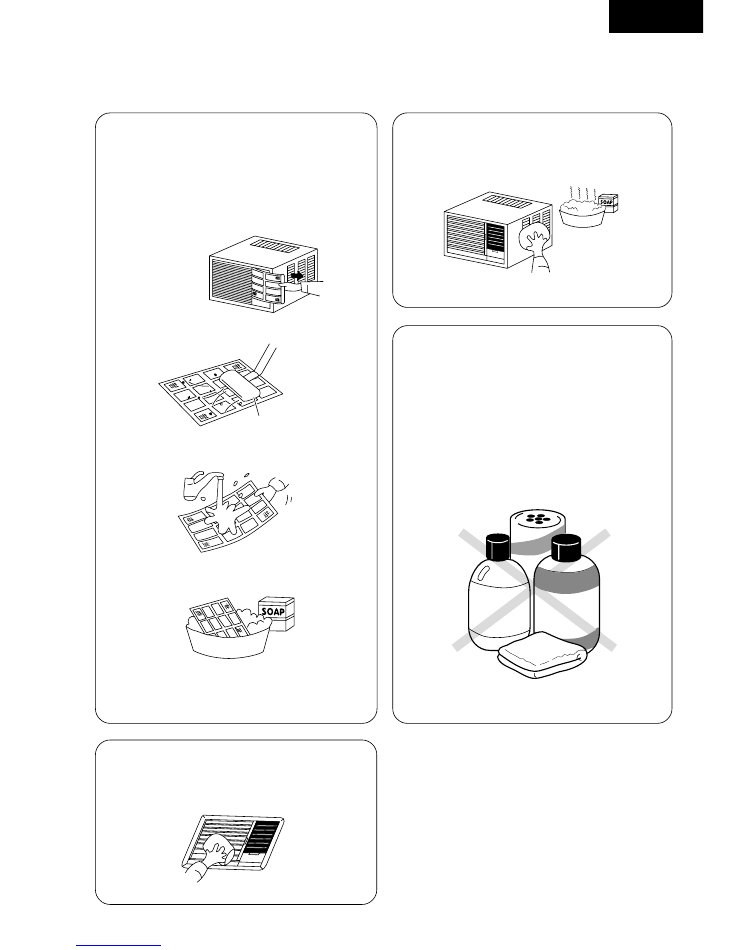
Always turn off the air conditioner and main power supply before cleaning to ensure safety.
CARE AND MAINTENANCE
Air Filter
The air filter behind the intake grille should be
washed at least every two weeks or as often as it
needs cleaning.
HOW TO CLEAN THE AIR FILTER:
1. To remove the air filter, grasp the tab on the filter
and pull to the right.
2. Vacuum the filter on the dusty side to remove
light dust.
3. Wash the filter, cleaner side up under gently flowing
water to wash out accumulated dust and lint.
4. If the filter is very dirty, use a mild household
detergent in the wash water.
Let the filter dry thoroughly before reinstalling it.
When reinstalling the filter, be sure the word “FRONT”
is facing you as you slide the filter back into place.
Front Grille
Clean the front grille with a clean cloth lightly
dampened with mild liquid dish-washing detergent.
Caution
Wipe off dirt with a soft, dry cloth (use a vacuum
cleaner to remove dust from the air intake.)
Use a cloth and water less than 40°C to remove
stubborn dirt (the cloth should be well-wrung).
Do not use the following cleansers as they cause
the paint to peel and lead to malfunctions:
Benzene, thinner, scouring powder, chemical-
soaked cloths, etc.
lukewarm water +
mild detergent
Vacuum cleaner
BENZENE
THINNER
Cabinet
Clean the cabinet with mild soap or detergent and
lukewarm water.
Annual check
* After long-term usage of room air conditioners, dust
and dirt will accumulate inside, lowering the perform-
ance. This may cause the generation of odour or may
impede the drainage of the dehumidifying water.
* Besides regular cleaning of the air conditioner, a
separate annual check is also recommended
(chargeable). Please request your dealer to carry out
these checks.
– 11 –
CW-C180BN
– 12 –
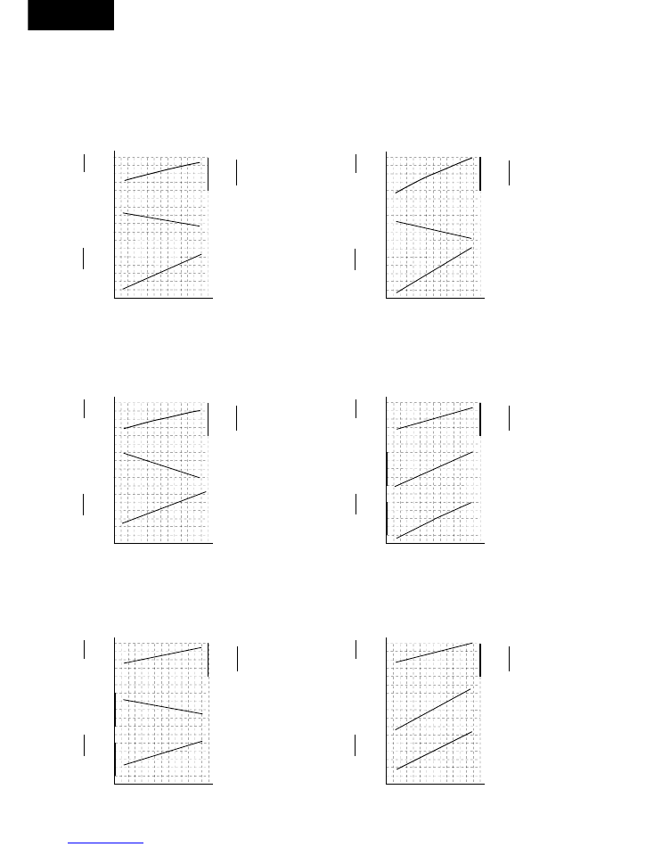
TECHNICAL
DATA
• Operation Characteristics
CW-C180BN
Cooling Characteristic
s
12.5
Voltage at 240–220V
11.5
10.5
s
O :
Outlet
Air Temperature (
o
C)
s
I
:
Current (A)
Q :
Cooling Capacity (KW)
30
35
40
Outdoor Air Temperature (
o
C)
Voltage at 240–220V
Voltage at 240–220V
CW-C240SN
Cooling Characteristic
CW-A180BN
Cooling Characteristic
CW-A240SN
Cooling Characteristic
Heating Characteristic
Heating Characteristic
s
50.0
Voltage at 240–220V
40.0
30.0
O :
Outlet
Air Temperature (
o
C)
I
:
Current (A)
Q :
Heating Capacity (KW)
-2
7
15
Outdoor Air Temperature (
o
C)
s
s
Voltage at 240–220V
s
11.5
Voltage at 240–220V
11.0
10.5
O :
Outlet
Air Temperature (
o
C)
Q :
Cooling Capacity (KW)
30
35
40
Outdoor Air Temperature (
o
C)
s
s
12.5
11.5
10.5
6.0
5.0
4.0
16.0
15.0
14.0
8.0
7.0
6.0
s
13.0
12.0
11.0
s
O :
Outlet
Air Temperature (
o
C)
s
I
:
Current (A)
Q :
Cooling Capacity (KW)
30
35
40
Outdoor Air Temperature (
o
C)
12.0
11.0
10.0
5.0
4.5
4.0
Q
O
I
s
O :
Outlet
Air Temperature (
o
C)
I
:
Current (A)
Q :
Cooling Capacity (KW)
30
35
40
Outdoor Air Temperature (
o
C)
s
s
7.0
6.0
5.0
Q
7.0
6.0
5.0
14.0
13.0
12.0
Q
O
I
s
50.0
40.0
30.0
O :
Outlet
Air Temperature (
o
C)
I
:
Current (A)
Q :
Heating Capacity (KW)
-2
7
15
Outdoor Air Temperature (
o
C)
s
s
5.5
4.5
3.5
11.0
10.0
Q
O
9.0
I
I
Q
O
O
Q
I
16.0
14.0
12.0
12.0
11.0
10.0
I
O
I
:
Current (A)
CW-C180BN
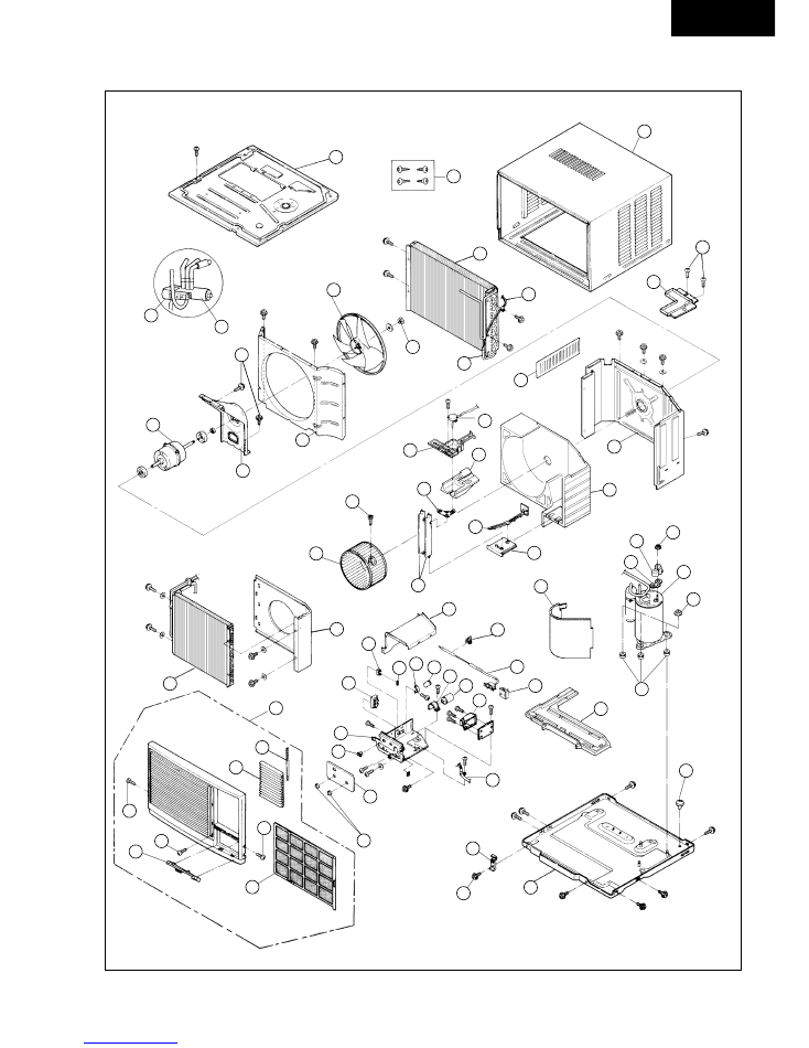
– 13 –
• The above exploded view is for the purpose of parts disassembly and replacement.
The non-numbered parts are not kept as standard service parts.
121
211
501
102
103
131
116
148
CW-C180BN, CW-A180BN
EXPLODED VIEW
CW-C180BE
106
712
210
212
122
217
323
300
703
312
146
610
710
145
123
120
135
101
207
200
202
144
147
128
308
304
109
129
311
306
125
508
509
507
500
220
707
502
505
100
130
600
117
112
205
203
310
329 126
326
303
124
302
711
201
702
707
707
613
CW-C180BN
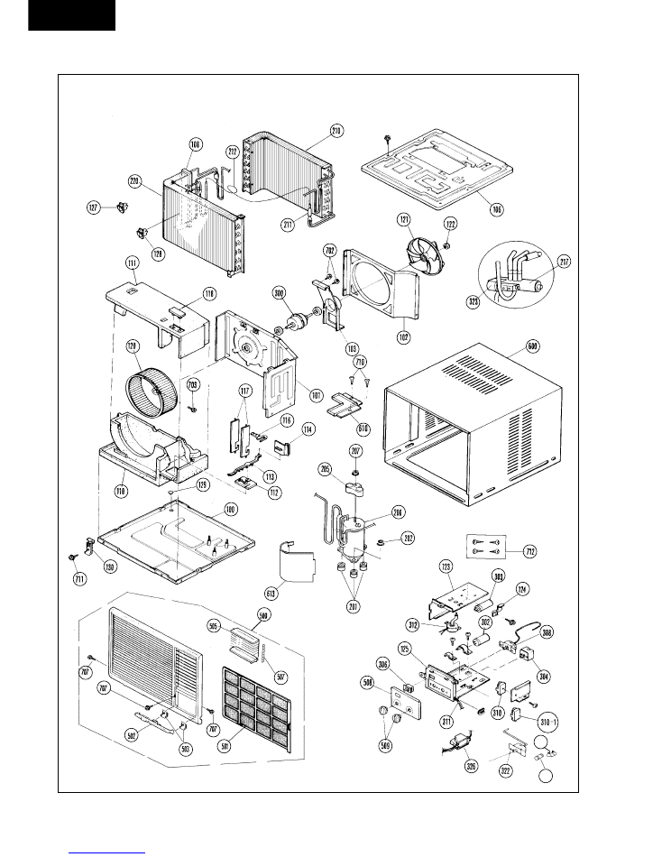
– 14 –
CW-C240SN, CW-A240SN
EXPLODED VIEW
EXPLODED VIEW
• The above exploded view is for the purpose of parts disassembly and replacement.
The non-numbered parts are not kept as standard service parts.
147
329
CW-C180BN
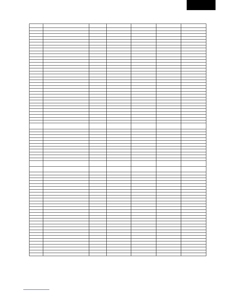
– 15 –
REF.NO.
DESCRIPTION & NAME
QTY
CW-C180BN
CW-A180BN
CW-C240SN
CW-A240SN
100
BASE PAN ASS'Y
1
CWD52K226A
CWD52K225A
CWD52K183A
CWD52K193A
101
BULKHEAD
1
CWD53K093
←
CWD53K087
CWD53K083
102
AIR GUIDER-PROPELLER FAN
1
CWD31092
←
CWD31K037
CWD31075
103
BRACKET-FAN MOTOR
1
CWD54091
←
CWD54142
←
106
TOP PLATE ASS'Y
1
CWD64K036
←
CWD64k029
←
108
COVER-EVAPORATOR
1
––
––
CWD11030
←
109
DRAIN TRAY-EVAPOPATOR
1
CWH40166
←
––
––
110
AIR GUIDER-B. WHEEL (BOTTOM)
1
––
––
CWD32099
←
111
AIR GUIDER-B. WHEEL (UPPER)
1
––
––
CWD32098
←
112
HOLDER-VENT. LEVER
1
CWD91021
←
CWD66156
←
113
VENTILATION LEVER
1
––
––
CWH22004
←
114
VENTILATION DOOR
1
––
––
CWH21012
←
116
CONNECTING BAR-A. SWING VANES
1
CWE26139
←
CWE26092
←
117
VANE-AIR SWING
2
CWE24314
←
CWC24210
←
118
GUIDER-A. SWING VANES
1
––
––
CWE26106
←
120
BLOWER WHEEL ASS'Y
1
CWH01K052
←
CWH01K056
←
121
PROPELLER FAN
1
CWH00009
←
←
←
122
NUT-P. FAN
1
CWH56033
←
←
←
123
CONTROL BOARD (AUX.)
1
CWD60384
←
CWH10K337
←
124
HOLDER-CAPACITOR (COMP.)
1
CWH30133
CWH30102
CWH30101
←
125
CONTROL BOARD (MAIN)
1
CWH10772
CWH10899
CWH10666
CWH10666
126
HOLDER-CAPACITOR (FAN)
1
CWH30132
←
––
––
127
HOLDER-SENSOR
1
––
––
––
CWH32048
128
HOLDER-SENSOR
1
CWH32085
CWH32086
CWH4690379
←
129
DRAIN PLUG-BASE PAN
1
CWH4611062
––
CWH4611062
––
130
CHASSIS LOCKING BRACKET
1
CWD93302
←
←
←
131
VENTILATION ASS'Y
1
CWH22007
←
––
––
135
AIR GUIDER-B. WHEEL
1
CWD32124
←
––
––
144
AIR GUIDER-B. WHEEL (FRONT)
1
CWD32126
CWD32126 (A)
––
––
145
RECTIFICATION PLATE
1
CWD21008
←
––
––
146
SPLASH WATER PROOF LOUVER
1
CWD91029A
––
––
––
147
FUSE HOLDER
1
XCSCW011
––
XCSCW011
←
148
BOX FOR AIR-SWING MOTOR
1
CWD66191
←
––
––
200
COMPRESSOR
1
2JS350D6BA02
2JS356D6DA01
2JS442D4AA01
←
(B09567)
(CWB09525)
(B09374)
201
BUSHING-COMP. MOUNT.
3
CWH50055
←
←
←
202
NUT-COMP. MOUNT.
3
CWH4582065
←
←
←
203
GASKET-TERMINAL COVER
1
CWH7070603
←
––
––
205
TERMINAL COVER-COMP.
1
CWH7070206
←
←
←
207
NUT-TERMINAL. COVER
1
CWH7080300
←
←
←
210
CONDENSER
1
CWB32604
CWB32484
CWB32C073
CWB32C095
211
STRAINER
1
CWB11025
←
←
←
212
CAPILLARY TUBE
2
CWB15491 (2)
CWB15363
CWB15315 (1)
CWB15589 (2)
217
4-WAY VALVE
1
––
CWB00003
––
CWB00003
220
EVAPORATOR
1
CWB30C049
←
CWB30C004
CWB30C015
300
FAN MOTOR
1
CWA95263
←
CWA92125
←
302
CAPACITOR-FAN
1
CWA31357
←
CWA31244
←
(3.5µF, 450VAC)
(3µF, 400VAC)
303
CAPACITOR-COMP.
1
CWA31504
CWA31506
←
←
(35µF, 370VAC)
(45µF, 370VAC)
304
MAIN CONTROL SWITCH
1
CWA07034
CWA07040
CWA07034
CWA07043
306
SWITCH-AIR SWING
1
CWA05024
←
←
←
308
THERMOSTAT ROOM
1
CWA15122
CWA15123
CWA15122
CWA15123
310
TERMINAL BOARD
1
CWA4711013
CWA4711060
CWA4711013
←
310-1
TERMINAL BOARD
1
––
––
––
CWA4711022
311
POWER SUPPLY CORD
1
CWA20C538
CWA20C643
CWA20C539
CWA20C481
312
AIR SWING MOTOR
1
CWA98K067
←
CWA98K046
←
322
SWITCH-LOW TEMP CUT
1
––
––
CWA15005
←
323
COIL-4 WAY VALVE
1
––
CWA43C365
––
CWA43C356
326
DEICER
1
––
CWA17004
––
CWA17004
329
FUSE
1
XBA2C50TR0
CWA16C158
XBA2C50TRO
←
500
FRONT GRILLE COMPLETE
1
CWE11C697
←
←
←
501
AIR FILTER
1
CWD00157D
←
←
←
502
GRILLE DOOR ASS'Y
1
CWE14K046
←
←
←
503
HINGE-G. DOOR
2
CWH61029E
←
←
←
505
VANE
14
CWE24301D
←
←
CWE24301D
507
LINK-VANES
1
CWE26136
←
←
←
508
CONTROL ESCUTCHEON
1
CWE311086
CWE311085
CWE311073
CWE311113
509
KNOB-TURNING
2
CWE17C076
←
←
←
600
CABINET COMPLETE
1
CWE00C121
CWE00C124
CWE00C120
←
610
DRAIN PAN
1
CWH40077
←
←
←
613
SOUND PROOF-COMP.
1
CWG30377
––
CWG30377
––
702
SCREW-BRACKET FAN MOTOR
4
CWH55039
←
←
←
703
SCREW-BLOWER WHEEL
1
CWH4580326
←
←
←
707
SCREW-F. GRILLE MOUNT.
1
CWH82C163
←
←
←
710
SCREW-DRAIN PAN
1
CWG86C733
←
←
←
711
SCREW-C. LOCKING BRACKET
1
XTT4+8B
←
←
←
712
SCREW-UNIT INSTALLATION
1
CWG86C280
←
←
←
OPERATING INSTRUCTIONS
1
F561189
←
←
←
All parts are supplied from MAICO, Malaysia (Vendor Code : 061).
• The above parts are kept for seven years in accordance with MEI service policy.
However, longer lead time will be taken in supplying the non-numbered parts.
REPLACEMENT PARTS LIST
CW-C180BN
– 16 –
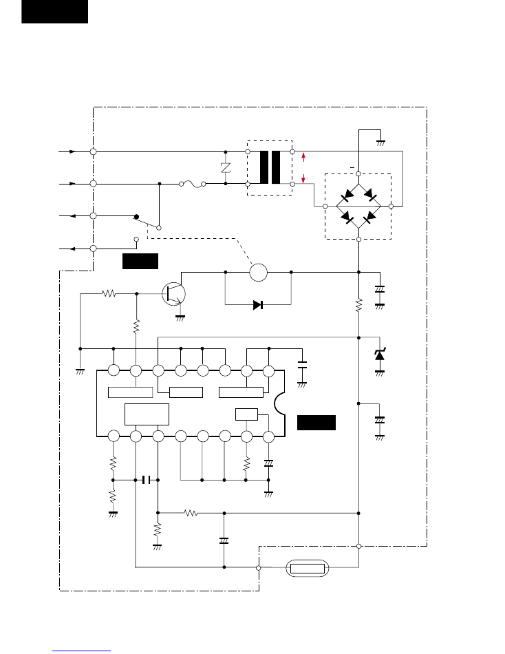
ELECTRONIC CIRCUIT DIAGRAM
•
CW-A180BN, CW-A240SN
(DEICER SCHEMATIC DIAGRAM)
D2
F14A
6.8
12.0
T
CWA40164
2 S C 1 3 1 8
DB1
SIVB10
10.0 VAC
ZNR
ERZC10DK471
IC
0.7
(0)
1 RED
2 BLUE
3 BLACK
4 YELLOW
NC
COM
NO
R2
6.8K
Ω
VCC
GND
AN6710
+C3
10V
33µF
R4
4.87K
Ω
R6
7.5K
Ω
+C4
16V
10µF
PIPING TEMP. SENSOR
~
~
7
9
0
(6.0)
C6
50V
4700PF
+C1
16V
470µF
R1
130
Ω
1W
POWER
OSC
PIPE
TEMP.
COUNTER
OUTPUT
+
Q
Ry
6
8
5
4
2
3
1
10
11
12
13
14
ZD
RD6. 8FB
16
15
R8
7.5K
Ω
R5
5.1K
Ω
R7
7.5K
Ω
R3
2.7K
Ω
0 (12.0)
+C2
10V
100µF
C5
50V
0.01µF

MAICO
Printed in Malaysia
F960500100TH