Full Text Searchable PDF User Manual
Quick Start Guide
Contents
Welcome……………………………………………………
2
Setup …………………………………………….…………
4
Home Theater Setup ……………………..………………
5
Stereo Setup ………………………………..……...………
9
Mod2 Assembly ………………………….………………. 11
Stud Zero & Stud Thirty Wall Mounts………………...
14
MultiMount & MultiPlate Wall/Ceiling Mounts…….
17
BOSS Table Stands ………………………………………
21
BOSS Wall Mounts…..……………………………….…..
24

Orb Audio LLC -- All Rights Reserved -- Quick Start Guide -- Page 2 of 24
Welcome
Congratulations on your purchase of our state of the art high fidelity speaker system and a
VERY BIG WELCOME to the Orb Audio family. Our company is different from most others
because -- we are a small, independent operation and we take great pride in providing a
superior, handmade product and great, intelligent service. Orb was created by audio
professionals who were tired of the status quo in the industry, where it is not uncommon to
spend more on marketing speakers than it costs to make them! You can be assured that your
Orb speakers feature only the highest quality components, design and craftsmanship. Thank
you very much for your purchase and trust in us.
Your new speaker system is not some mass-produced system that you will see everywhere,
knowing that you paid hundreds or thousands of dollars in advertising costs and retail
markups. Your speakers are not made of plastic, all Orb satellites are made in the USA by
skilled craftspeople using only audiophile quality components. Our innovative business model
allows us to design and manufacture extremely high quality speakers and avoid the
tremendous markups and other pitfalls prevalent in the retail consumer electronics industry. In
short, your system has been designed in the United States by people that are passionate about
home audio and who started their own company to make the speaker systems that they have
always dreamed of.
We choose to sell our products primarily over the internet because it allows us to reach our
design goals without compromise and without our products becoming overly expensive. It is
more difficult to get exposure this way, but we are a small, employee-owned company and we
prefer to sell a manageable number of speaker systems each month directly to our customers,
rather than use traditional retail distribution that would double or triple the price of our
speakers without making them any better. In addition to making great speakers, we also pride
ourselves on providing great service, and this means that you will talk to knowledgeable
decisionmakers every time you call or email us. We are happy to try and meet the individual
needs of all of our clients, and our nimble size allows us to do this with great success. We are
Small Speakers For Smart People, and you are a smart person for choosing Orb.
You will be rewarded for your choice with a system that we have designed to:
* Produce the richest and fullest sound from a compact satellite/subwoofer system. This
means your speaker system will sound like large speakers, but will fit in the décor of
any room. Your system will sound integrated and complete, and you will not be
plagued by the "boom and sizzle" of inferior speakers systems.
* Reproduce an audio signal with amazing clarity and detail, and with astonishing
imaging and soundstage. You will likely notice for the first time nuances in music that
you have heard many times and with which you thought you were completely familiar.
Our state of the art drivers and speaker design are changing the price/performance
expectations of audio consumers all over the world.

Orb Audio LLC -- All Rights Reserved -- Quick Start Guide -- Page 3 of 24
* Produce massive, yet tight and musical bass from small, attractive subwoofers. After all,
what would be the point of selling small speakers if our subwoofers ate up all of your
floor space? If the Super Eight were sold in stores, it would be more expensive than our
Mod1 system that includes 5 speakers & the subwoofer! Many speaker systems skimp
on the subwoofer, while we have designed an instant classic that excels at both movies
and music and provides tight, accurate bass under all conditions. Don’t even get us
started on the Uber Ten...
* …and lastly, you have chosen a system designed to carry itself with the style demanded
by the high performance of it's design. Our speakers just don't sound good, they look
great, too. Say goodbye to plastic cubes and boxy, ugly speakers. Our round speakers,
stylish subwoofers and designer accessories ensure that your Orb system will be
something you are glad to welcome into your home.
If you have had the chance to listen to other speaker systems, you will find that our speakers
can outperform most systems substantially above our price range. We are not geniuses, we are
simply doing what you would do if you were able to design your own speaker from scratch --
we are cutting out the middlemen and markups and spending your money on quality
components, assembly and cutting edge industrial design. Selling direct is not a complicated
idea, but it works, and it means you get a better product for your money, and we can keep
designing our speakers with performance and design as our only two concerns.
A Word About Break-In
Like all speaker systems, our speakers require a little time to break in. They will
sound great out of the box, but even better as they play for a couple of hours over
the first few days. Use the speakers normally during the break in period. There
is no need to break in the speakers any other way. As you play them, you will
notice that the output from the satellites becomes more well-rounded and the
output from the subwoofer becomes tighter and louder. You will also notice
that the overall integration between the satellites and subwoofer improves as the
speakers break in. You might have to adjust the volume of the subwoofer during
the break in period to best match the satellites. Once a balance has been
achieved, you will probably not have to make many changes unless there are
differences in the dynamic range or recording of your various audio sources.
WARNING: AS WITH ALL ELECTRONICS, THE WIRING OF SPEAKERS MUST BE
DONE CORRECTLY OR CAN CAUSE PHYSICAL INJURY OR HARM TO PROPERTY,
INCLUDING ELECTRICAL SHOCK. PLEASE FOLLOW ALL INSTRUCTIONS AND
WARNINGS IN THE MANUAL FOR YOUR AMPLIFIER/RECEIVER OR CONTACT YOUR
MANUFACTURER IF NECESSARY. THIS QUICK START GUIDE IS NOT INTENDED TO
BE A SUBSTITUTE FOR CONSULTING THE MANUALS THAT CAME WITH YOUR
AMPLIFIER/RECEIVER OR CONTACTING THE MANUFACTURER OF YOUR
ELECTRONICS COMPONENTS IF NECESSARY.

Orb Audio LLC -- All Rights Reserved -- Quick Start Guide -- Page 4 of 24
Setup
If you are using a home theater receiver with a subwoofer output (most people), please
follow the home theater instructions below, in conjunction with the directions that came
with your receiver. If you are setting up a Classic One or Classic Two stereo system,
without using a subwoofer cable only, see the STEREO SETUP instructions on page 13.
Most speaker systems do not come with instructions because setup is largely
determined by the amplifier or receiver you will be using. To setup our speakers, you
must also consult the manual for your amplifier/receiver. To help you better
understand most manuals, which can vary greatly in quality and detail, we have
included a basic description of how our speakers are generally set up on most systems.
Do not use this as a substitute for the instructions provided by the manufacturer of your
audio equipment, but rather as a supplement to point you in the right direction.
We try to set ourselves apart with service as much as we do with great speakers. We
are available to assist you via email at support@orbaudio.com or via phone at (877) 672-
2834 (877-ORB-AUDIO).
Quick Tips
Auto Setup:
If your receiver has an auto setup program, it is OK to use it.
However, we also recommend checking each of the settings it has selected, as
receivers have been known to do some crazy, inexplicable things. The most
important of these is the individual volume settings for each speaker.
Verify that no
individual speaker (or the subwoofer) has been set to more than +/- 1 or 2 dB by
the auto setup.
Small changes to volume settings go a long way and settings of
more than +1 or +2 can increase the likelihood of damage to your speakers. Settings
of more than +/– 2 dB are RARELY required and should be reduced to +/- 2 dB.
Receiver Mode:
Dolby Digital and DTS sound great if your source material is
mastered (well) in 5.1, such as DVDs. Most other times, we recommend “ALL
CHANNEL STEREO” mode or similar mode, especially for CDs and most TV.
Wire & Cables:
Red and white RCA cables connecting your components will no
longer cut it: your DVD, cable TV, etc. must be connected to the receiver with a
digital cable (HDMI, optical or coaxial) to transmit Dolby Digital or DTS.
Upgrading:
If you want to upgrade to Mod2 or Mod4 speakers, it is very simple
and can be done in minutes. Also, we don’t charge you a penalty for upgrading or
adding to your system, you will get the full benefit of our best package pricing.

Orb Audio LLC -- All Rights Reserved -- Quick Start Guide -- Page 5 of 24
Home Theater Setup
(All Receivers With Subwoofer Output)
Most home theater installations are pretty straightforward. Before we get into the specifics,
simply remember this: all you have to do is connect your subwoofer and Mod1 or Mod2
satellite speakers to your receiver or amplifier, then adjust the settings on your receiver and
subwoofer.
Nearly every home theater receiver has a “subwoofer out,” “subwoofer,” or “LFE” output jack
and you will connect your subwoofer using this dedicated output. Your satellite speakers will
then connect directly to your receiver, with each speaker being connected to the appropriate
output (left front, center front, right front, right surround, left surround, right surround rear,
left surround rear, etc.) using speaker wire. For most people, setup will be this simple.
If you
have different components, such as a 2 channel stereo receiver or amplifier without a
subwoofer output, we have included alternative setup instructions later in this guide.
If you have experience setting up home theaters, here is a very simplified checklist of what you
need to do:
1. Assemble your speakers (Complete directions for Mod2, BOSS stands, wall mounting,
etc. begin on p. 11). You must assemble each speaker before wiring.
2. Connect your speakers to speaker outputs on receiver using speaker wire.
Each Mod2
or Mod4 speaker only requires one regular run of speaker wire from the receiver.
Make sure you maintain polarity on every connection (Red to Red, Black to Black).
3. Connect subwoofer from SUB OUT on receiver to LINE IN on subwoofer.
4. Set up subwoofer (master power ON, power mode toggle switch to ON or AUTO, X-
OVER DISABLED, PHASE to zero (front of room) or 180 (elsewhere).
5. Set audio settings on receiver (small speakers, crossover 100-120hz, individual volume
on speakers and sub not to exceed +/- 1 or 2 dB).
DIRECTIONS TO CONNECT TO HOME THEATER RECEIVER
1. Assemble Your Speakers
Assemble all of your speakers and then continue with system setup. Each speaker will
screw onto a wall mount, desk stand, floor stand or Mod2 COZY bracket. If you have Mod1
speakers, simply attach them to the included desk stands using our Easy Turn thumbscrew.
If you have Mod2 or Mod4 speakers, or are using wall mounts or specialty BOSS or HOSS
stands, you must assemble them before proceeding. Instructions for Mod2 assembly, wall
mounts and BOSS stands begins on page 11 of this manual. Assemble each speaker and
then return here to begin connecting them to your receiver.
2. Connect Your Satellite Speakers To Your Receiver
Your next step is to connect your satellite speakers directly to the speaker outputs on your
receiver, using speaker wire. Each speaker will connect to the positive and negative
terminals on one speaker output on your receiver.
Mod2 and Mod4 speakers only require
one normal run of speaker wire to the receiver.

Orb Audio LLC -- All Rights Reserved -- Quick Start Guide -- Page 6 of 24
Connect each Mod1, Mod2 or Mod4 speaker to your receiver by
depressing the custom
binding post on the satellite speaker
and inserting the speaker wire into the holes that
open up. You will notice that each binding post has a hole for speaker wire on the top and
on the bottom. With a Mod1 speaker, you may insert the speaker wire into either hole.
With a Mod2 or Mod4 speaker, you will insert the speaker wire into the bottom hole of the
lower speaker, and then use the included black or white jumper wire to connect each
additional sphere to the one that is connected to the receiver with speaker wire. Detailed
instructions and photos relating to Mod2 and Mod4 assembly are available in our detailed
Mod2 and Mod4 guides, including instructions on how to assemble a horizontal Mod2
center channel.
It is very important to maintain polarity.
Make sure that each positive (red) and negative
(black) terminal on your receiver is connected to the corresponding positive (red) and
negative (black) binding posts on your Orb speakers. Almost all speaker wire has some sort
of indication to allow you to identify each side of the wire (typically one copper and one tin
wire, or printing on one side of the wire only). It does not matter which side of the speaker
wire you initially make positive or negative (i.e. copper side = positive), but follow this
same pattern for every connection in the system.
Depending on the level of your experience, the large number of input jacks, binding posts
and spring clips on some receivers can seem overwhelming. Don’t let it deter you. Take it
one step at a time, connect one speaker at a time and it is easy – just five, six or seven of the
exact same connection, depending on whether you have a 5.1, 6.1 or 7.1 receiver.
And, we
are always happy to assist you over the telephone or via email.
3.
Connect Your Subwoofer To Your Receiver
PLEASE NOTE there will be nothing connected to the red and black speaker
wire terminals on the back of the Subwoofer (these are only for receivers
without a dedicated subwoofer output, see p. 11 below).
Use a subwoofer cable to connect the gold plated LINE IN on your subwoofer to the
SUBWOOFER OUTPUT on your receiver. If your receiver is a surround sound receiver
capable of five or more channels of sound, it will have a dedicated audio output for the
subwoofer somewhere on the back of the receiver. It is commonly labeled as
“SUBWOOFER OUT”, but can also be called “PRE-OUT” or “LFE OUT.” Please check your
receiver manual (or call/email us) if you need assistance locating this output.
4. Set Up Your Subwoofer (Super Eight/Uber Ten)
One Sentence Description
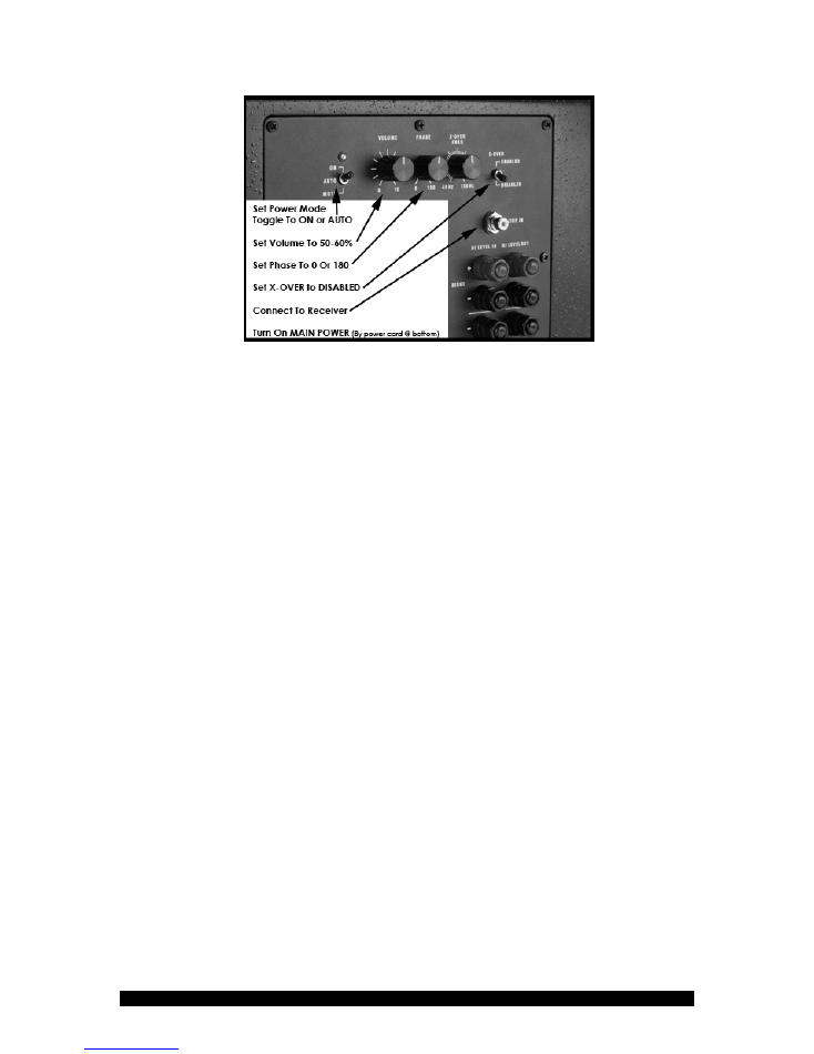
Plug in subwoofer, set TWO power switches (MASTER POWER SWITCH, above power
cord, to ON and ON/AUTO/MUTE toggle switch to ON or AUTO), set VOLUME to 50%,
X-OVER to DISABLE and PHASE to 0 (front of room) or 180 (rear).
Orb Audio LLC -- All Rights Reserved -- Quick Start Guide -- Page 7 of 24
Super Eight Pictured (Uber Ten Has Same Dials, In Vertical Orientation)
Full Description
Locate the
MASTER POWER SWITCH
(above the power cord) and the
ON/AUTO/MUTE
toggle switch (next to the small LED light) on the back of your subwoofer, because you will
need both of these to turn on your subwoofer. Connect the included power cable to the
subwoofer, make sure the MASTER POWER SWITCH is in the OFF position, and plug in
your subwoofer to your power outlet. Now, turn the subwoofer on by engaging the
MASTER POWER SWITCH
just above the power cable on the back of the subwoofer. A
red LED should be lit at the top left of the amplifier plate.
Next, set your power mode to either
ON or AUTO
if you are ready to use the subwoofer.
The power setting must be set to either ON (active at all times) or AUTO (active only when
receiving a signal) in order to produce output. The AUTO mode will automatically put the
subwoofer into a power conserving SLEEP mode when no audio signal is detected for
approximately 15 minutes. The subwoofer will also automatically wake up as soon as it
detects audio signal above a certain relatively low volume (NOTE: very low volumes may
not trigger the subwoofer AUTO detect).
VOLUME:
For most people, the VOLUME should be set at roughly one-half (VOLUME set
at 12 O’clock position) of the output of the sub. Some prefer a little lower, some a little
higher, and it all depends on room size, source material and personal preference. As the
subwoofer breaks in, you may want to adjust the VOLUME up or down.
PHASE:
Start with it set at 0 if the subwoofer is in the front of the listening area and at 180
if it is placed in the rear or to the side of the listening area. You can adjust in either direction
as your tastes dictate.
There is no correct phase setting and it is not uncommon for the
subwoofer to sound similar at every setting.
Your subwoofer has a variable phase control. Phase is the degree to which the satellite
speakers and subwoofer are either “pushing” or “pulling” at the same time. A phase setting
of zero means they are both pushing and pulling at the same time, whereas a setting of 180
indicates one is pushing while the other is pushing.

Orb Audio LLC -- All Rights Reserved -- Quick Start Guide -- Page 8 of 24
X-OVER TOGGLE SWITCH:
Set the X-OVER toggle switch to
“DISABLED”
if you are
installing your subwoofer as part of a surround sound system using a home theater receiver.
You will not need to use the crossover in the Super Eight or Uber Ten subwoofers. Instead,
you will use the crossover controls in your receiver.
X-OVER FREQ:
When the X-OVER toggle switch is set to DISABLED, the setting of the X-
OVER FREQ dial is irrelevant and the dial is not used.
5. Set Up Your Receiver
Once you have connected your speakers, the next step is to setup your receiver to work
properly with your Orb system. This is an easy, but critical step. Most home theater
receivers have tailored settings for large and small speakers, as well as customizable
crossovers and bass management options. After connecting your speakers to the receiver,
you will need to adjust these settings.
If your receiver has an auto setup program, it is OK to use it. However, we also
recommend checking each of the settings it has selected, as receivers have been known to
do some crazy, inexplicable things.
First and foremost, if you use an auto setup program,
please check and make sure that no individual speaker (or the subwoofer) has been set to
more than +/- 1 or 2 dB. Small differences in volume settings go a VERY long way and auto
setup programs tend to make excessive adjustments in this area. Settings of more than +1 or
+2dB can greatly increase the possibility of damage to your speakers.
Also, if you use an auto setup program, or if you choose to set up your receiver manually,
the other settings are as follows:
First, set the speaker size to “SMALL” or similar choice and set the subwoofer to “ON” or
“LFE+MAIN” if given the choice.
If your receiver has a variable crossover option, select a crossover anywhere between 80hz
and 150hz (recommended 100hz or 120hz) for each channel regardless of whether you are
using Mod1 or Mod2 speakers.
If your receiver has "dynamic compression" or a similar
setting, you should turn it to "off."
What modes should you use on your receiver?
We are very big fans of “ALL CHANNEL
STEREO,” “5 CH STEREO,” “7 CH STEREO” and similar immerseive stereo surround
modes. If you are listening to a source that is not recorded in 5.1 (i.e. all CDs and most TV),
this is usually the best listening mode.
If you are listening to a source that is recorded in 5.1 (i.e. most DVDs and some TV) and you
are using a digital cable (HDMI, optical or coaxial) to transmit the signal from the source to
the receiver, then you may also find that Dolby 5.1 or DTS mode sounds best. These modes
require the receiver to receive an encoded 5.1 signal and will not work with red and white
RCA cables or with source material that was not recorded in 5.1 or 7.1 surround sound.
Dolby Digital 5.1 and DTS usually put all of the dialogue in the center channel and use the
other speakers only for surround effects. On some movies this is great, on others it results

Orb Audio LLC -- All Rights Reserved -- Quick Start Guide -- Page 9 of 24
in a more narrow soundstage than we prefer. If you find this happening, experiment with
“ALL CHANNEL STEREO” mode or similar mode.
Many receivers have additional options such as dynamic compression and digital signal
processing ("Stadium," "Concert Hall," etc.). To the extent these can be turned off, we
recommend doing so.
You are done…go find your favorite, well-recorded CD and enjoy!
Stereo Setup
(Receivers Without Subwoofer Output)
Basic Idea:
If you are setting up a stereo system,
and your receiver does not have a subwoofer
output
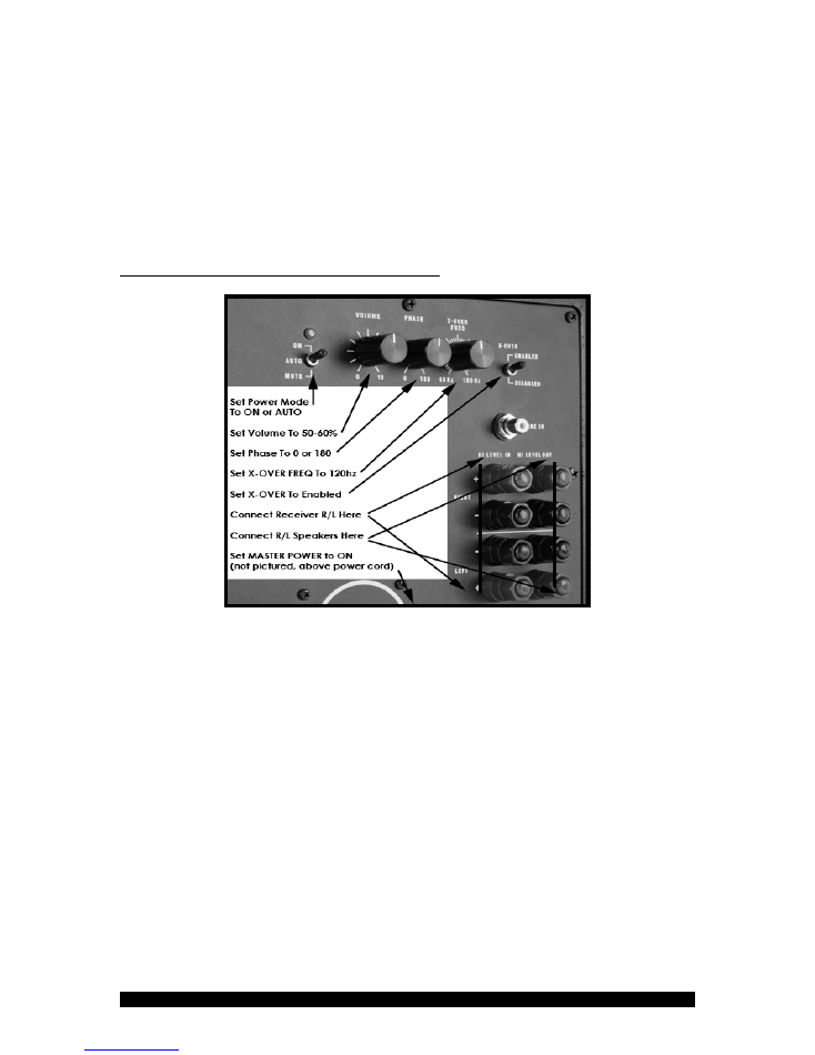
, follow these directions. You will connect the main left and right speaker outputs on
your receiver to the left and right HIGH LEVEL INPUT on the subwoofer, then connect the left
and right satellite speakers to the HIGH LEVEL OUTPUT on the subwoofer, all with speaker
wire. Your subwoofer will go “between” the satellite speakers and the receiver and the
subwoofer will split the signal between itself and the speakers.
In this instance, there will be
nothing connected to the single gold plated audio input marked “LINE IN.”
1. Connect Your Subwoofer And Speakers
Connect the Super Eight or Uber Ten Subwoofer to your receiver by running standard speaker
wire from the Red (+) and Black (-) Main Right and Main Left Speaker terminals on your
Receiver to the corresponding Red (+) and Black (-) speaker wire terminals on the back of the
subwoofer marked “HI LEVEL IN”. As always, be sure to maintain polarity throughout the
connection process. Also make sure you are connecting the speaker wire to the correct
terminals on the subwoofer, and not adjacent terminals (i.e. make sure you haven’t connected to
one or two of the HIGH LEVEL OUT terminals yet). You should have a length of speaker wire
run from the left speaker output on your receiver (positive and negative) to the left HI LEVEL
IN on the subwoofer (positive and negative) and a second run connecting the right speaker to
the right speaker output on your receiver.
Next, take a separate run of speaker wire from the “HI LEVEL OUT” Red (+) and Black (-)
speaker wire terminals on the back of the Super Eight Subwoofer and connect those to the
corresponding Left and Right Main mod1 or mod2 Speakers in your system.
Connect each Mod1, Mod2 or Mod4 speaker to the speaker wire by
depressing the custom
binding post on the satellite speaker
and inserting the speaker wire into the holes that open
up. You will notice that each binding post has a hole for speaker wire on the top and on the
bottom. With a Mod1 speaker, you may insert the speaker wire into either hole. With a Mod2
or Mod4 speaker, you will insert the speaker wire into the bottom hole of the lower speaker,
and then use the included black or white jumper wire to connect each additional sphere to the
one that is connected to the subwoofer with speaker wire. Detailed instructions and photos
relating to Mod2 and Mod4 assembly are available in our detailed Mod2 and Mod4 guides,
including instructions on how to assemble a horizontal Mod2 center channel.
Orb Audio LLC -- All Rights Reserved -- Quick Start Guide -- Page 10 of 24
It is very important to maintain polarity.
Make sure that each positive (red) and negative
(black) terminal on your receiver is connected to the corresponding positive (red) and negative
(black) binding posts on your Orb speakers. Almost all speaker wire has some sort of indication
to allow you to identify each side of the wire (typically one copper and one tin wire, or printing
on one side of the wire only). It does not matter which side of the speaker wire you initially
make positive or negative (i.e. copper side = positive), but follow this same pattern for every
connection in the system.
2. Set Up Your Subwoofer (Super Eight/Uber Ten)
Locate the
MASTER POWER SWITCH
(above the power cord) and the
ON/AUTO/MUTE
toggle switch (next to the small LED light) on the back of your subwoofer, because you will
need both of these to turn on your subwoofer. Connect the included power cable to the
subwoofer, make sure the MASTER POWER SWITCH is in the OFF position, and plug in your
subwoofer to your power outlet. Now, turn the subwoofer on by engaging the
MASTER
POWER SWITCH
just above the power cable on the back of the subwoofer. A red LED should
be lit at the top left of the amplifier plate.
Next, set your power mode to either
ON or AUTO
if you are ready to use the subwoofer. The
power setting must be set to either ON (active at all times) or AUTO (active only when
receiving a signal) in order to produce output. The AUTO mode will automatically put the
subwoofer into a power conserving SLEEP mode when no audio signal is detected for
approximately 15 minutes. The subwoofer will also automatically wake up as soon as it detects
audio signal above a certain relatively low volume (NOTE: very low volumes may not trigger
the subwoofer AUTO detect).
VOLUME:
For most people, the VOLUME should be set at roughly one-half (VOLUME set at
12 O’clock position) of the output of the sub. Some prefer a little lower, some a little higher, and
Orb Audio LLC -- All Rights Reserved -- Quick Start Guide -- Page 11 of 24
it all depends on room size, source material and personal preference. As the subwoofer breaks
in, you may want to adjust the VOLUME up or down as your taste dictates.
PHASE:
Start with it set at 0 if the subwoofer is in the front of the listening area and at 180 if it
is placed in the rear or to the side of the listening area. You can adjust in either direction as
your tastes dictate.
There is no correct phase setting and it is not uncommon for the
subwoofer to sound similar at every setting.
Your subwoofer has a variable phase control. Phase is the degree to which the satellite speakers
and subwoofer are either “pushing” or “pulling” at the same time. A phase setting of zero
means they are both pushing and pulling at the same time, whereas a setting of 180 indicates
one is pushing while the other is pushing.
X-OVER TOGGLE SWITCH:
Set the X-OVER toggle switch to
“ENABLED”
since you will be
using the crossover in the subwoofer.
X-OVER FREQ:
Experiment to find your personal preference, most typically between 80hz and
150hz. 100-120hz is recommended is generally the sweet spot.
3. Set Up Your Receiver
Consult your receiver manual for proper setup. When set up through an Orb subwoofer, your
receiver should treat the speakers as large, full-range speakers. You are done…go find your
favorite, well-recorded CD and enjoy!
Mod2 Assembly Instructions
The Mod2 is easy to assemble and requires no tools. If you have the BOSS table stands, please
turn to the last few pages of this manual for assembly instructions.
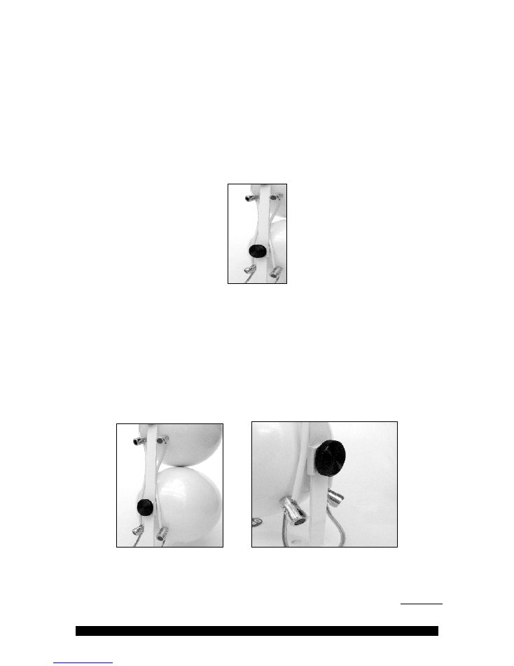
1.
The Mod2 is made up of two individual speaker spheres. The first step is to take one
Easy Turn Thumbscrew and attach the lower speaker to the desk stand. This will also
Orb Audio LLC -- All Rights Reserved -- Quick Start Guide -- Page 12 of 24
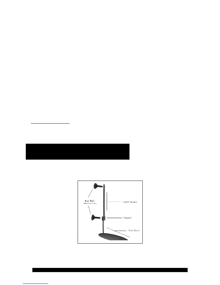
secure the COZY bracket for the upper speaker. To do this, take an Easy Turn
Thumbscrew and put it through the desk stand, then through the COZY bracket as
illustrated (with the “channel” facing toward the thumbscrew), into the back of one
speaker. The gold-plated binding posts on the speaker should be facing down, and the
vertical post on the stand should be between the binding posts. Tighten the thumbscrew
until it has a snug fit.
2.
Take the second thumbscrew, put it through the top hole on the COZY bracket, and
tighten it into the hole on the back of the upper speaker enclosure. The binding posts
should be facing down, and the COZY bracket should be between the binding posts.
3.
The two spheres must now be connected to one another with the included jumper wires.
The binding posts have holes on top and bottom that open when you depress the
binding post. Use one jumper wire to go from the red binding post on the bottom
speaker to the red binding post on the top speaker. The jumper wire will go from the
top hole of the lower binding post, into the hole on the underside of the upper speaker.
Connect the black binding posts in the same manner with one of the other included
jumper wires.
The connections on the back the Mod2 look like this. The left photo shows a complete Mod2
and the right photo is a close up of the bottom sphere, showing speaker wire and jumper wire
connections.
3.
The speaker wire from the receiver is connected only to the bottom speaker enclosure on
the Mod2. To do this, depress the binding posts on this speaker and insert the speaker
wire into the holes on the bottom of the binding posts. Once you do so, you should have
the speaker wire from the amplifier/receiver going into the holes on the underside of
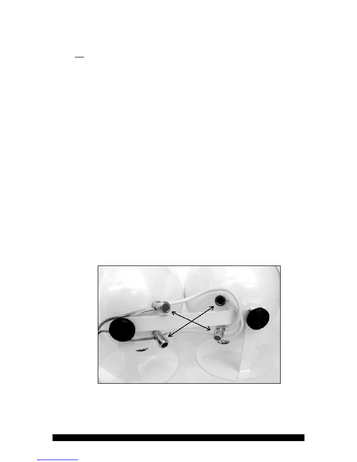
Orb Audio LLC -- All Rights Reserved -- Quick Start Guide -- Page 13 of 24
the binding posts on the bottom speaker enclosure, and the jumper wires running from
the top hole of these binding posts to the corresponding binding posts on the upper
speaker enclosure. If you have difficulty fitting in the speaker wire and jumper wire, try
putting in the speaker wire first. Please note: you must consult the manual or
manufacturer of your amplifier/receiver for proper set up instructions, because
instructions vary from model to model. Generally, you must make sure you connect the
wires throughout your system without reversing the colors or polarity. It is important
that all speakers be set up exactly the same and that the red and black binding posts are
wired consistently to the matching positive or negative connections on your
amplifier/receiver. You may damage your speakers or equipment if you do not wire
correctly or cause other physical injury or damage to property. Wiring is specific to each
model of amplifier and receiver, so please consult your manual.
4.
Repeat these steps to set up each additional Mod2 speaker. If you are assembling a
center channel, you can set up the Mod2 horizontally by following the instructions in the
next paragraph.
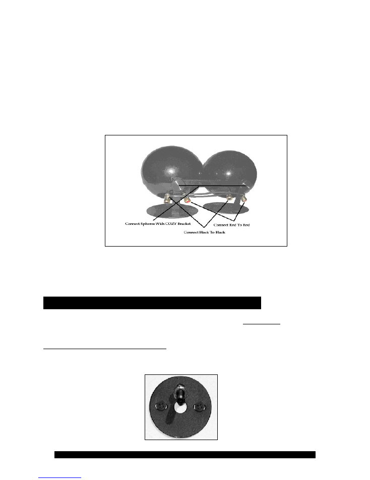
5.
The Mod2 can also be assembled horizontally, most commonly for use as a center
channel. The basic setup idea is the same and the picture below illustrates this type of
assembly. There are two ways to set up the Mod2. For the easiest assembly, you can
give each speaker a 1/4 turn inward so that the binding posts are now closer together
and facing each other in the center of the combined speaker, as shown below. Connect
red post to red post using the included jumper wires, and do the same for the black
posts. Please note that after you turn each speaker, the positive (red) and negative
(black) terminals are now on opposite sides of the speakers. Consequently, you must
now wire the top terminal on one speaker to the bottom terminal on the other to
maintain polarity.
You may either direct the jumper wire around the binding posts, as shown above, or
you may cut the jumper wire to the exact length you need to cover the distance between
the binding posts. Some jumper wire is already precut in this length. After connecting
the jumper wires, you can then connect the spheres with the included COZY bracket,
Orb Audio LLC -- All Rights Reserved -- Quick Start Guide -- Page 14 of 24
although you do not have to. Note: there is no effect on performance when you turn
the speaker, because it is round and performs exactly the same regardless of orientation.
Additionally, the binding posts will still be invisible from the front of the speaker.
If you'd prefer to leave the speakers oriented with the binding posts down, you can you
can cut a custom length of regular speaker wire and connect the two spheres that way.
You can use the same speaker wire that you are using to connect the Mod2 to your
receiver. You might also be able to use the included jumper wires if you bend the
exposed ends of the included jumper wires down at 90 degrees before attempting to
insert them into the binding posts.
6.
It is now time to connect your Mod2 speakers to your receiver. Your speaker wire can
be connected to either sphere, but must be connected to the same sphere. So, take care
to ensure that your speaker wire is connected to the black and red post on the same
sphere.
Stud Zero & Stud Thirty Wall Mounts
NOTE:
If you are mounting a center channel or other speaker
horizontally
, please read
“Horizontal Center Mounting” later on in this guide.
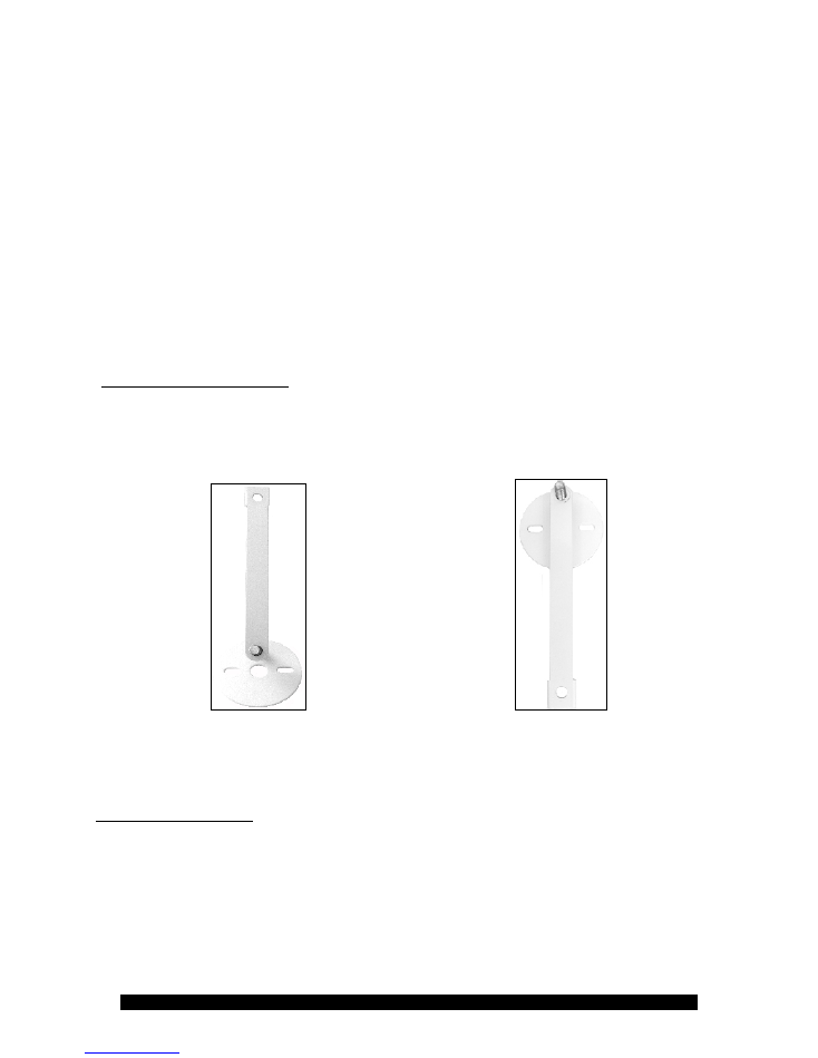
1. Attach The Stud Mount To Your Wall
Using the supplied screws and wall anchors, mount your Stud Zero/Stud Thirty on the wall
as shown:
Orb Audio LLC -- All Rights Reserved -- Quick Start Guide -- Page 15 of 24
If you have a Mod1, screw it on to the Stud Zero/Thirty until the gold binding posts are
almost but not quite touching the stud mount. Using a small pliers or wrench, tighten the
locking nut on the wall mount until it locks against the speaker firmly, holding it in place.
Next, connect the speaker wire as shown earlier, being careful to maintain polarity. If you
have speaker wire coming out of your wall, you may use the center hole in the wall mount
to conceal the wire. It is important that the binding posts do not touch the wall mount, as
this could cause a short and damage your speakers or receiver or cause other damage.
If you are only using Mod1 speakers, you are done at this step. The remaining directions
concern installing a VERTICAL Mod2 speaker.
If you are installing a Mod2, the second speaker will hang below the first speaker for the
Stud Zero, and above the second speaker with the Stud Thirty. Make sure you leave enough
room for the total height of two Orb satellites, around 10 inches.
2. Install the COZY Bracket
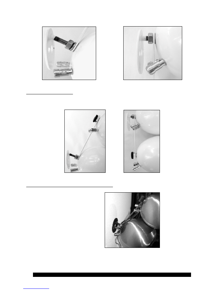
Once the Stud Mount is on the wall, the next step is to attach the COZY bracket. Back up the
locking nut far enough to mount the first Orb in the next step, almost all the way. Put on the
COZY bracket with the rounded end on the stud and the little metal "channel" facing the wall
and away from the speakers.
Stud Thirty Stud Zero
With the Thirty (left) the Cozy must stand off above the stud so that the speakers lean off the
wall. With the Zero (right) the Cozy hangs below the stud. Only the Thirty needs a lockwasher
between the locking nut and the Cozy bracket as shown in the photo for step 3.
3. Install The First Orb
Simply screw it on by hand until the gold posts are almost but not quite touching the mount.
Make sure that neither gold post is actually touching the mount as this can cause a short.
Position the Orb with the gold posts facing down and tighten the locking nut using a small
wrench or pliers. The COZY must be vertical before you lock it down fully or the assembled
Mod2 will not be straight. As shown in these detailed photos:
Orb Audio LLC -- All Rights Reserved -- Quick Start Guide -- Page 16 of 24
4. Install the Second Orb
Add on the second Orb by putting the thumbscrew through the COZY bracket and into the Orb.
Tighten by hand until snug. Check to see if both speakers line up straight.
5. Install The Jumper Wires And Speaker Wire
Install the two jumper wires and
the speaker wire from your
receiver. Complete instructions
are in our Mod2 Assembly
Guide. The jumper wire will go
from BLACK to BLACK and
from RED to RED. The speaker
wire will connect to one read
and black post on ONE
SPEAKER ONLY (typically the
bottom speaker).
Orb Audio LLC -- All Rights Reserved -- Quick Start Guide -- Page 17 of 24
HORIZONTAL MOUNTING – STUD ZERO AND STUD THIRTY
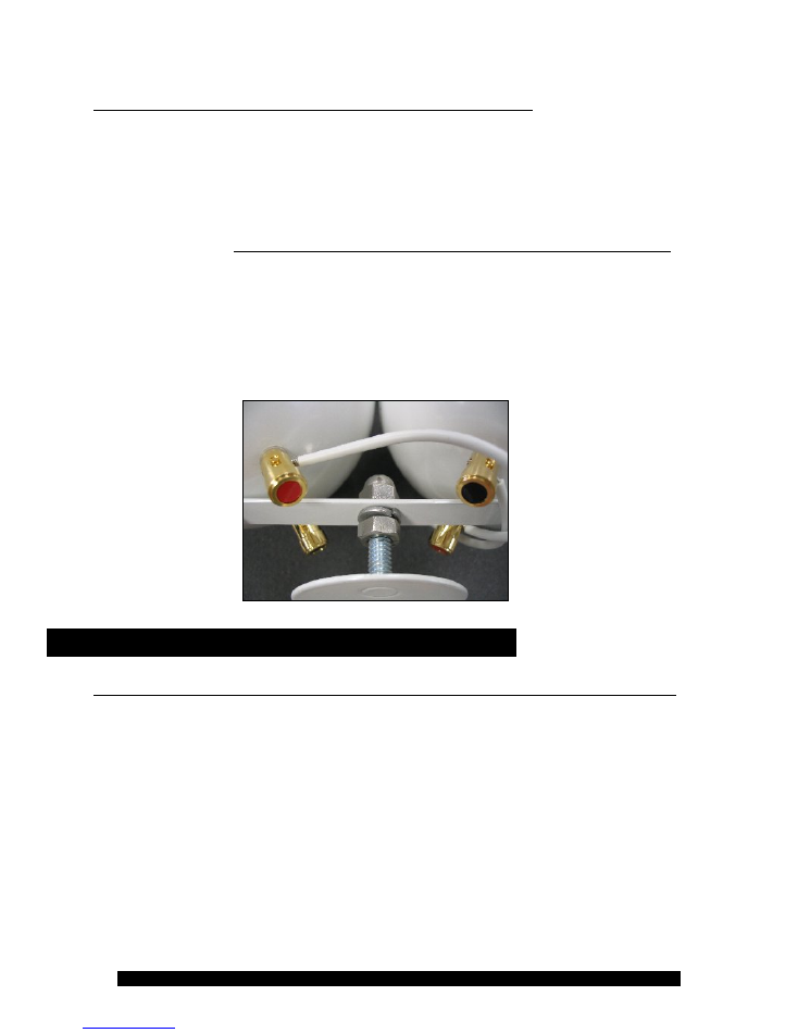
1. Attach the Stud Zero or Stud Thirty mount to the wall as shown above in section 1.
2. Find the COZY bracket with the hole punched in the center. One is included for every
horizontal front center channel and any other channel you may have requested to be
horizontal. Assemble your Mod2 horizontally on the COZY bracket by attaching each
speaker to the COZY bracket with a thumbscrew. Full instructions are in the Mod2
Assembly Guide.
Make sure the jumper wire goes from black to black and red to red
.
3. Position the hex-nut and the lock-washer near the end of the threaded bolt extending from
your Stud Thirty or Stud Zero Wall Mount. Slide the open center hole onto that bolt and
fasten with the acorn-shaped nut, “sandwiching” the bracket between the hex nut, the lock-
washer and the acorn nut on the threaded bolt. Tighten this screw with a wrench or small
plier and you are done. A picture of this assembly is shown below.
MultiMount & MultiPlate Instructions
If you are mounting a speaker horizontally, follow the directions at the end of this guide.
The Orb Multimount is a very simple yet very flexible mounting solution. You will bend the
metal post to reach your desired angle. The Orb can be mounted on either side of the post to
reach almost any angle. The Orb MultiPlate Mount includes the same flexibility and fits on a
standard junction box. The mounting instructions are the same for the MultiPlate and
MultiMount, the only difference being in the portion that is actually mounted to the wall. A
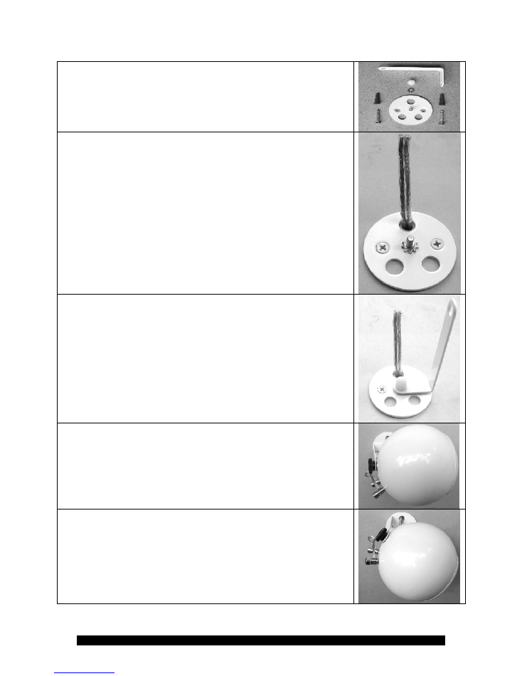
MultiMount includes the round disk shown below, MultiPlate includes a junction box cover.
Orb Audio LLC -- All Rights Reserved -- Quick Start Guide -- Page 18 of 24
This is the complete parts kit that should be included with your
MultiMounts. The MultiPlate mount will include the same
hardware, except substituting a junction box plate for the main
circular disk of the multimount.
We recommend attaching an Orb to the assembled MultiMount
before drilling to ensure that you end up with your wires under a
hole and behind the gold posts on your Orb speaker. Then mark
your holes and install the base plate as shown.
There are three wire through holes to ensure a neat installation no
matter what mounting options you choose.
Note the star washer on the central post. This is necessary to prevent
slippage once the full weight of the speakers is on the Post.
Attach the post to the central screw using the nylon acorn nut. You
can tighten it down with a small wrench or a pair of pliers. You can
always change the angle after installation but it is much easier before
the speakers are installed.
Note: The 8/32 steel screw and nylon nut can be tightened by hand
or with a tool. The goal is to allow the star washer to bite into the
powder coated surfaces and prevent the parts from slipping. You do
not need a great amount of force, generally hand tight plus an extra
turn with a tool will be sufficient.
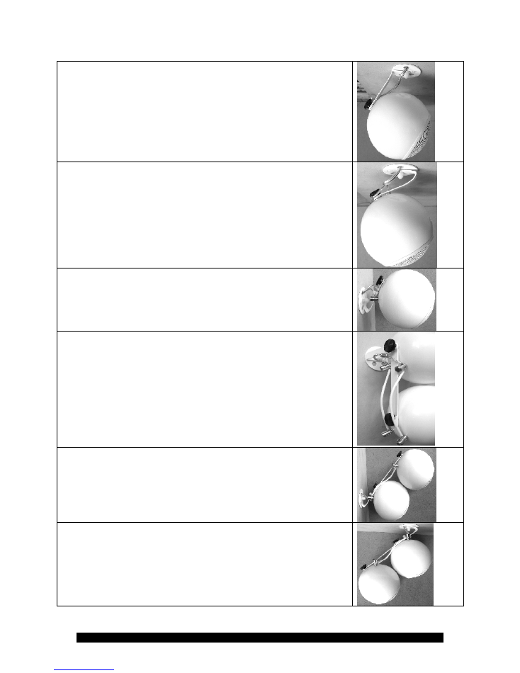
MultiMounts are often used in the rear channels. The most common
rear channel orientation (5.1) is for both speakers to fire across the
back wall, above and behind the listening position. In this photo, the
speaker is mounted on the rear wall and fires across the room. You
can bend the post to angle the speaker to meet your needs.
Depending upon aesthetics, mounting height and listening position,
you can point the speakers down (if the listening position is against
the back wall)
Orb Audio LLC -- All Rights Reserved -- Quick Start Guide -- Page 19 of 24
(shown here from top view)
…and then angle them slightly into the room if the listening position
is 3-4 feet off the rear wall…
Note: This same configuration can be used for ceiling mount or side
walls.
…or angle them in much more if the listening position is in the
middle of a large space.
When more angle is required, install the Orb on the outside of the
post and bend the post in towards the base plate.
Note: This same configuration can be used for ceiling mount or side
walls.
Another common use is to mount the speakers high up on the front
walls and angle them down into the room.
Mod2 installation is very similar to Mod1 and just as easy. We will
now include the use of our Cozy bracket to join the two speakers
together. Some helpful pointers:
1) If the Mod2 must fire across the wall the Cozy will be attached at a
right angle to the MultiMount post. The Cozy has a channel at one
end. This must be on the bottom speaker and facing out as pictured
in this photo. Once the speaker is assembled as shown you can bend
the post to aim the speakers off the wall or you can loosen the acorn
nut to angle the Mod2 down into the room.
2) If the Mod2 is to be angled down into the room off the front wall,
the Cozy is attached in line with the MultiMount post such that the
channel locks onto the post, still facing out. The Cozy is between the
Orb and the post. In other words, the thumbscrew will go first
through the Cozy channel, then the post and into the Orb.
The instructions for ceiling mount use are identical.
Orb Audio LLC -- All Rights Reserved -- Quick Start Guide -- Page 20 of 24
Horizontal Center Mount Instructions
MultiMount & MultiPlate
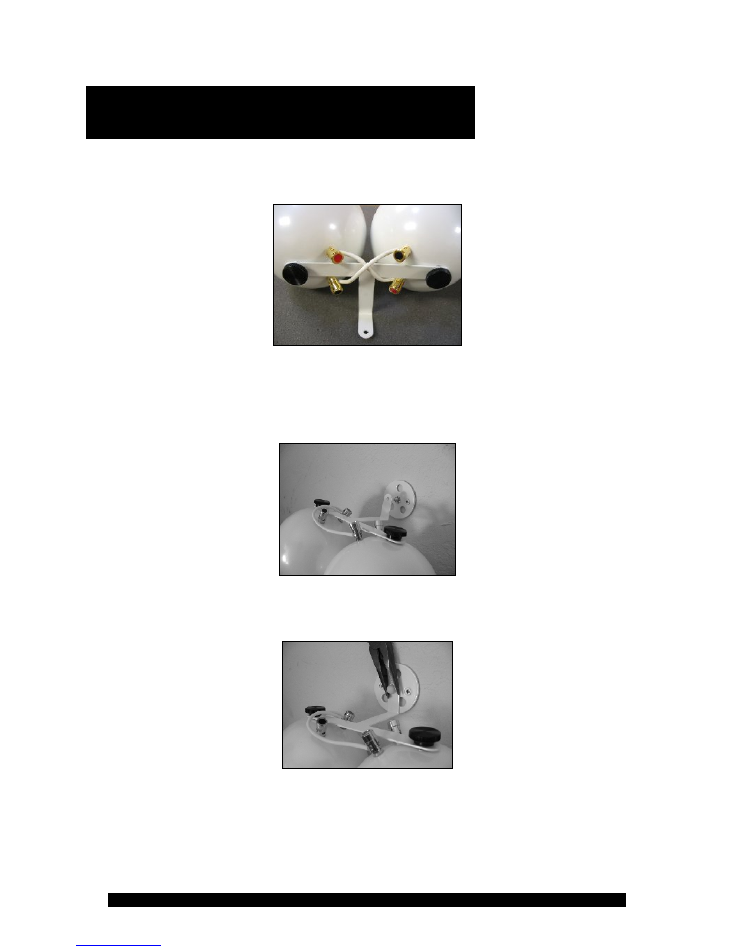
Assemble your mod2 horizontally on the T-Cozy Bracket as show below and complete the
wiring, RED TO RED and BLACK TO BLACK, as seen here, in an X pattern:
Please make sure the binding posts are wired RED TO RED and BLACK TO BLACK, in an X
pattern.
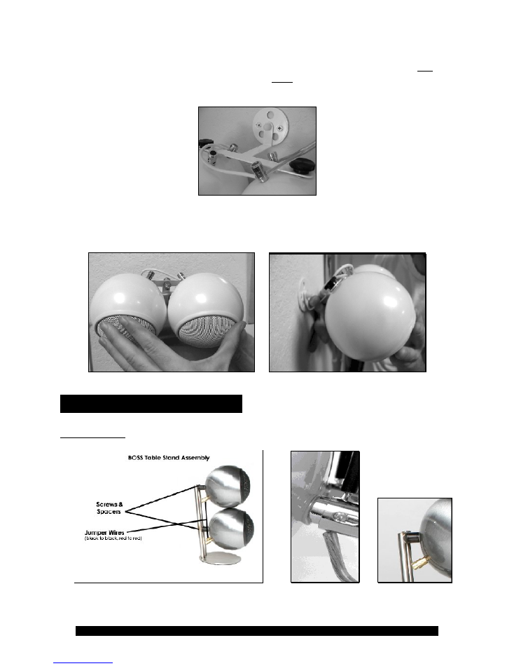
Once you have assembled the mod2 on the T-Cozy bracket and connected the jumper
wires between the two speakers, the T-Cozy bracket will attach to the mount in the same
manner as the standard MultiMount and Multi Plate. See below:
Tighten the nut to secure the T-Cozy Bracket to the MultiMount or MultiPlate. Be sure to use
the star washer provided to help the nut grip the center channel bracket:
Orb Audio LLC -- All Rights Reserved -- Quick Start Guide -- Page 21 of 24
Once the T-Cozy bracket is secured to the mount, you can connect the amplifier lead to one of
the satellites (one RED and one BLACK post on the same speaker):
Once the assembly is completely tight you can bend the T-Cozy bracket to the desired angle. Be
sure to support both the satellites and the short end of the T-Cozy brackets firmly when
bending the bracket to the desired angle.
BOSS Stand Assembly
Vertical Stands
Orb Audio LLC -- All Rights Reserved -- Quick Start Guide -- Page 22 of 24
1. Place the BOSS stand on a flat surface. Insert one of the screws through the bottom hole on
the BOSS stand. Insert one spacer on the screw. The spacer will go between the metal stand
and speaker, not behind the metal stand. In other words, it goes on the front of the stand.
2. Attach the bottom Orb by screwing it onto the screw. Tighten loosely with a screw driver.
Attach the top Orb the same way if you have a Mod2.
3. Connect the jumper wires (included) to the speakers, maintaining polarity (black to black,
red to red). The jumper wire goes into the top hole of the binding post on the bottom speaker,
and into the corresponding hole on the bottom of the binding post on the top speaker.
4. Connect the speaker wire from your receiver to the bottom Orb, using the holes on the
bottom of the binding post on the bottom speaker.
IF YOU HAVE A MOD2, ONLY ONE ORB
GETS WIRED TO YOUR RECEIVER
. Be careful to maintain polarity between the connections
on the speaker and receiver (black to black, red to red).
Horizontal Stands
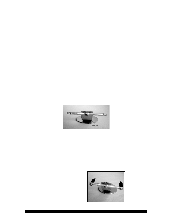
1. Install The Aluminum Crossbar
To install the aluminum crossbar, you must first back out the set screw. Unscrew the screw to
the point that it is not visible in the round channel that accepts the crossbar.
Next, insert the aluminum crossbar. Be careful not to scratch the finish and make sure the set
screw does not extend into the round channel before inserting the bar. Visually center the bar
from left to right. There are no markings, and you can adjust it again later.
Next, orient the crossbar upward slightly so that you can install the remaining pieces easily.
You can change the angle later to point in the desired direction. Now tighten the set screw
using a screwdriver. Your goal is for the crossbar to be tilted upwards just enough such that the
black spacers installed in the next step do not slide off during installation.
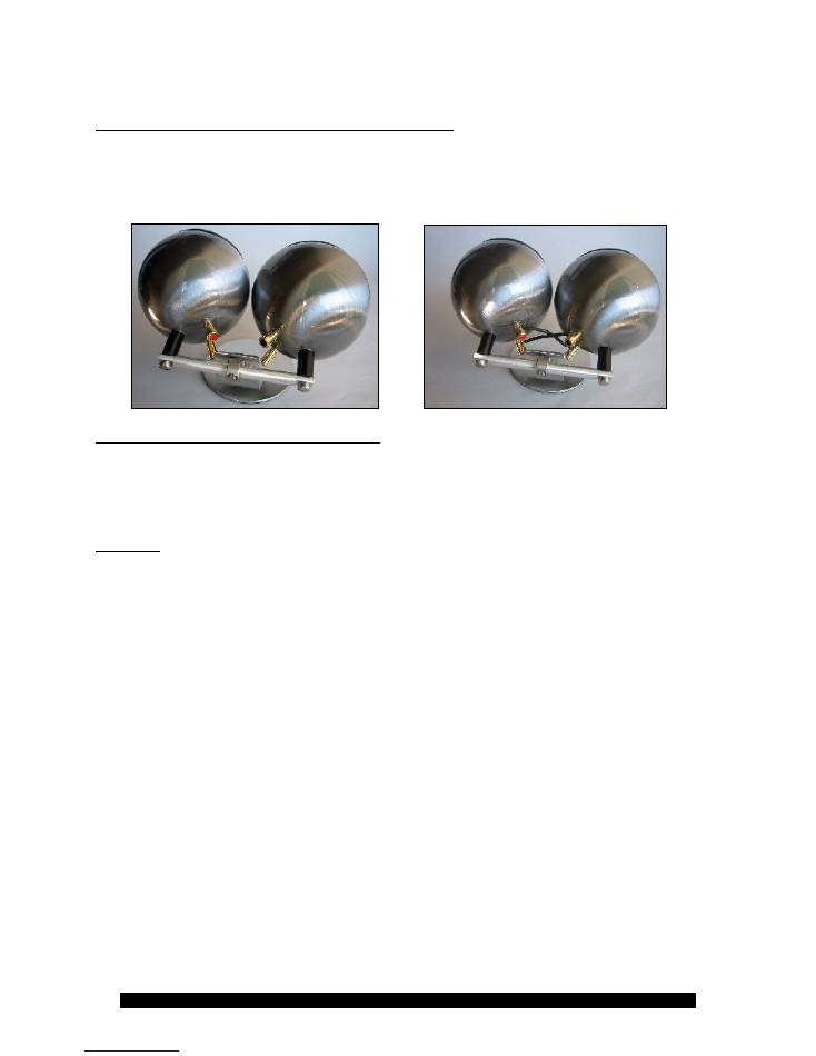
2. Install The Screws And Spacers
Install the screws and spacers as shown:
Orb Audio LLC -- All Rights Reserved -- Quick Start Guide -- Page 23 of 24
3. Install The Satellites & Connect The Jumper Wires
Using a screwdriver, install the two Orb satellites as shown. Binding posts will end up in a
‘crisscross’ pattern with red and black next to one another on top and bottom.
Using the short jumper wires, connect red to red and black to black, forming an “X” pattern.
4. Connect The Speaker To The Amplifier
Connect the black and red terminal from
ONE SATELLITE ONLY
to your amplifier. Make
sure that you maintain polarity between black and red going from your amp to this and
every speaker in the system. Your speaker wire should have a marking on one side to make
this easier.
5. Adjust
Loosen the set screw and adjust the speaker to the final angle that best suits your need. Tighten
set screw firmly and enjoy!
Orb Audio LLC -- All Rights Reserved -- Quick Start Guide -- Page 24 of 24
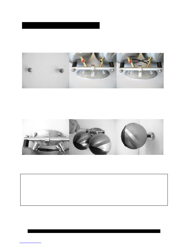
BOSS Wall Mount Assembly
Use the BOSS mount to mark the
Assemble the speaker on the BOSS
Connect the jumper wires in an X
desired locations for your speaker. stand. Turn the speakers so that the
pattern. RED to RED and BLACK
red binding post on one speaker is
to BLACK.
opposite the black post on the other.
Attach the assembled speaker and Tighten the screws. Do not
Side view of mounted speaker.
mount to the screws in the wall. It overtighten. Adjust the Orbs to
Run speaker wire to the RED and
is easiest if you loosen the set screw the desired angle and tighten the
BLACK binding posts of ONE
and aim the speakers downward. set screw that holds the crossbar.
Orb.
Thank you for purchasing an Orb Audio stereo speaker system. As a small employee-owned
company, we make it our mission to provide you with the best products and the best customer
service. We are available to assist you via email at support@orbaudio.com or by calling our
technical support line at (877) 672-2834. If you are happy with your purchase, please tell your
friends!