Full Text Searchable PDF User Manual
Onyx.
Advanced car security solutions
16 Shapira St. Rishon Le - Zion 75052, Israel
Tel: 972-3-9413313 ; Fax: 972-3-9413330
www.onyxtech.co.il ; info@onyxtech.co.il
Page 1 of 12 EGPRS Unit User Guide
EGPRS™
User Guide
Version: 1.2
January 2009
Contact Us:
ERM Electronic Systems
16 Hsar Shapira st. Rishon-Lezion, 75704, Israel
TEL: +972-3-9413313, FAX: +972-3-9413330
www.onyxtech.co.il
support@onyxtech.co.il

Onyx.
Advanced car security solutions
16 Shapira St. Rishon Le - Zion 75052, Israel
Tel: 972-3-9413313 ; Fax: 972-3-9413330
www.onyxtech.co.il ; info@onyxtech.co.il
Page 2 of 12 EGPRS Unit User Guide
Table of Contents
1
Product Description
.........................................................................................................3
2
Block Diagram - HW components
.................................................................................5
2.1 GPS Module
.............................................................................................................
5
2.2 GSM operating frequency
........................................................................................
5
2.3 Peripheral communication
.......................................................................................
6
2.4 Physical description
.................................................................................................
7
3
Installation Guide
...........................................................................................................11
3.1 EGPRS Vehicle Installation
...................................................................................
11
Table of Figures
Figure 1 - Product Overview ................................................................................... 4
Figure 2 - EGPRS Unit: Block Diagram.................................................................. 5
Figure 3 - EGPRS module ....................................................................................... 7
Figure 4 - GPS module............................................................................................ 7
Figure 5 - Connectors Mapping...................................
האיגש
!
היינמיסה
תרדגומ הניא
.
Figure 6 - Up View ................................................................................................. 11
Figure 7 - SIM Card insertion................................................................................ 11
Figure 8 - GPS Module .......................................................................................... 12

Onyx.
Advanced car security solutions
16 Shapira St. Rishon Le - Zion 75052, Israel
Tel: 972-3-9413313 ; Fax: 972-3-9413330
www.onyxtech.co.il ; info@onyxtech.co.il
Page 3 of 12 EGPRS Unit User Guide
1
Product Description
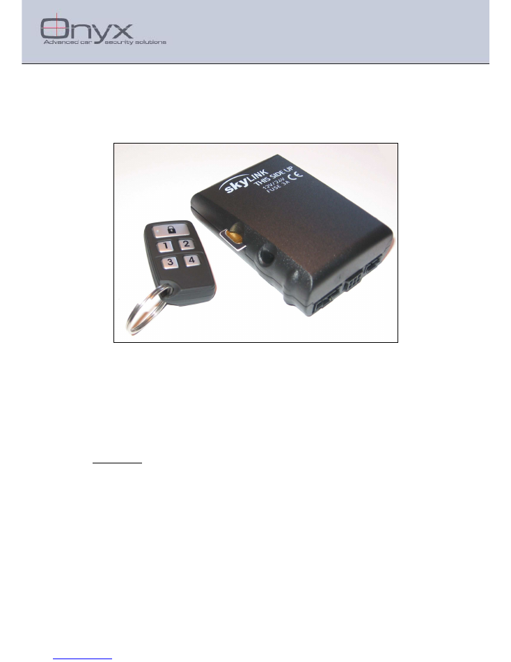
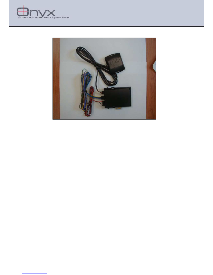
The EGPRS Cellular Monitoring Unit is a self and independent device which
provides a cost effective solution for monitoring and controlling vehicles such
as: trucks, privates and motorbikes. This is accomplished by locating and
tracking them over the cellular wireless network. The EGPRS communicates
over the GSM cellular network (for a visual car's whereabouts over a map).
The EGPRS unit is a GPS GSM device that can also be connected to other
vehicles indicators (alarm, speed, engine etc...).
The EGPRS is composed of the following modules:
•
Internal GSM/GPRS engine
•
Internal antenna
•
Internal backup battery
•
External GPS module
•
Controller and I/O circuits
The EGPRS is a GSM / GPRS unit which uses GPRS IP communication (or
SMS) in order to send and receive information regarding the vehicle status and
location. The EGPRS contains a GPS to provide the vehicle’s location data.
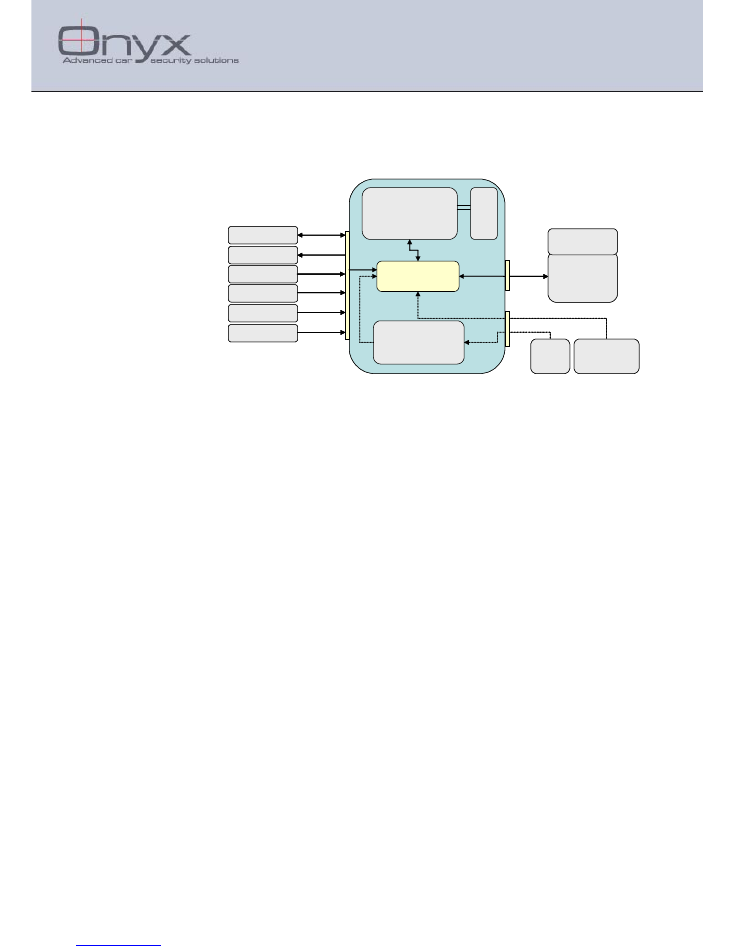
The Micro controller and GSM transceiver are the core elements of the EGPRS,
as illustrated in the following block diagram (Figure 2).
The Micro controller
is the core of the EGPRS. It runs the application program
and communicates with the GIS Server and peripheral devices to collect
information. It can respond to or issue commands.
The Micro controller interfaces with the GPS over the RS-232 channel.
The charger is fed from the car battery to charge the internal backup battery.
The internal backup battery has the ability to be used for up to 10 hours under
normal operating conditions when external power is disconnected. The EGPRS
utilizes status triggered charging algorithm in order to not harm the internal
batteries.
The SIM module holds the relevant IP address used to identify the unit as well
as other subscriber identification parameters registered in the system upon
activation.
Onyx.
Advanced car security solutions
16 Shapira St. Rishon Le - Zion 75052, Israel
Tel: 972-3-9413313 ; Fax: 972-3-9413330
www.onyxtech.co.il ; info@onyxtech.co.il
Page 4 of 12 EGPRS Unit User Guide
Figure 1 - Product Overview
Onyx.
Advanced car security solutions
16 Shapira St. Rishon Le - Zion 75052, Israel
Tel: 972-3-9413313 ; Fax: 972-3-9413330
www.onyxtech.co.il ; info@onyxtech.co.il
Page 5 of 12 EGPRS Unit User Guide
2
Block Diagram - HW components
The following block diagram shows the main HW components composing the
EGPRS unit:
Figure 2 - EGPRS Unit: Block Diagram
GSM/GPRS
Modem
Microcontroller
Rechargeable
Battery
GPS
Receiver
RS232
GSM
Ant.
GPS
Patch Ant.
Port A - Purple
Port B - Gray
Port D - Green
Port E - Yellow
Port F - Brown
Digital/Analog Input/Output
Digital Input Line - Ignition
Port C - Blue
RS485
Digital Output Line
Digital Input Line
Digital Input Line
Alarm System
(Optional)
power
source
9-32 V
+/-
Digital Input Line - eNet
2.1
GPS Module
The GPS receiver simultaneously tracks up to sixteen satellites and provides
accurate satellite positioning data with fast time-to-first-fix (TTFF) with low
power consumption. The highly integrated receiver achieves high performance
and minimizes board size and power consumption requirements.
The module provides complete signal processing from antenna to serial data
output in NMEA messages protocol.
The GPS device is fed and communicates with the EGPRS over a RS-232
serial channel at a 9600bps baud rate. The GPS device holds the GPS receiver
with an antenna on top of it.
2.2
GSM
operating frequency
The EGPRS can operate over the GSM-900 MHz, DCS-1800 MHz and PCS
1900 MHz bands:
1.
GSM-900, GSM-850:
The unit in GSM-900/850 operating mode is of
class 4, in accordance with the specifications, which determines the
nominal 2W peak RF power (+33dBm) on 50 Ohm and sensitivity
greater than -102dBm in all operating conditions.
2.
DCS-1800, PCS 1900:
The unit in DCS-1800 operating mode is of class
1, in accordance with the specifications, which determines the nominal
1W peak RF power (+30dBm) on 50 Ohm and sensitivity greater than -
102dBm in normal operating conditions.

Onyx.
Advanced car security solutions
16 Shapira St. Rishon Le - Zion 75052, Israel
Tel: 972-3-9413313 ; Fax: 972-3-9413330
www.onyxtech.co.il ; info@onyxtech.co.il
Page 6 of 12 EGPRS Unit User Guide
2.3
Peripheral communication
The Micro controller interfaces with the alarm system over the RS-485 channel
and with the GPS over the RS-232 channel. The eNet bi-directional channel is
able to carry information between various sensors and devices connected to the
bus.
The charger is fed from the car battery to charge the internal backup battery.
The internal backup battery has the ability to be used for up to 10 hours under
normal operating conditions when external power is disconnected. The EGPRS
utilizes status triggered charging algorithm in order to not harm the internal
batteries.
2.3.1
RS-232
This serial communication protocol supports communication over a common
data line. The EGPRS Micro controller communicates with the GPS device over
this data line.
2.3.2
RS-485
The EGPRS Micro controller communicates with the alarm system devices over
the RS-485 data line.
2.3.3
eNet
This bi-directional serial communication protocol can be used to connect
peripheral devices to the EGPRS such as: alarm units, a portable printer,
warning lights, distress buttons, and more.
One of the Open Collector/eNet single line interfaces can be configured as
eNet. The eNet bus must have a single master and up to 10 slave devices.
2.3.4
Single Wire Discretes
The EGPRS supports six single line interfaces (Inputs only) of types as listed
below:
•
3 General Purpose Input Discrete – one of which can be used for VSS
Odometer measuring, and one optionally supports eNet bi-directional
communication (See above).
•
1 digital output – 12v active 200ma.
•
1 Ignition line (dedicated Input discrete).
•
1 that can be used as an input or output (according to configuration) and
can be defined to digital or analog.
Onyx.
Advanced car security solutions
16 Shapira St. Rishon Le - Zion 75052, Israel
Tel: 972-3-9413313 ; Fax: 972-3-9413330
www.onyxtech.co.il ; info@onyxtech.co.il
Page 7 of 12 EGPRS Unit User Guide
2.4
Physical description
2.4.1
EGPRS
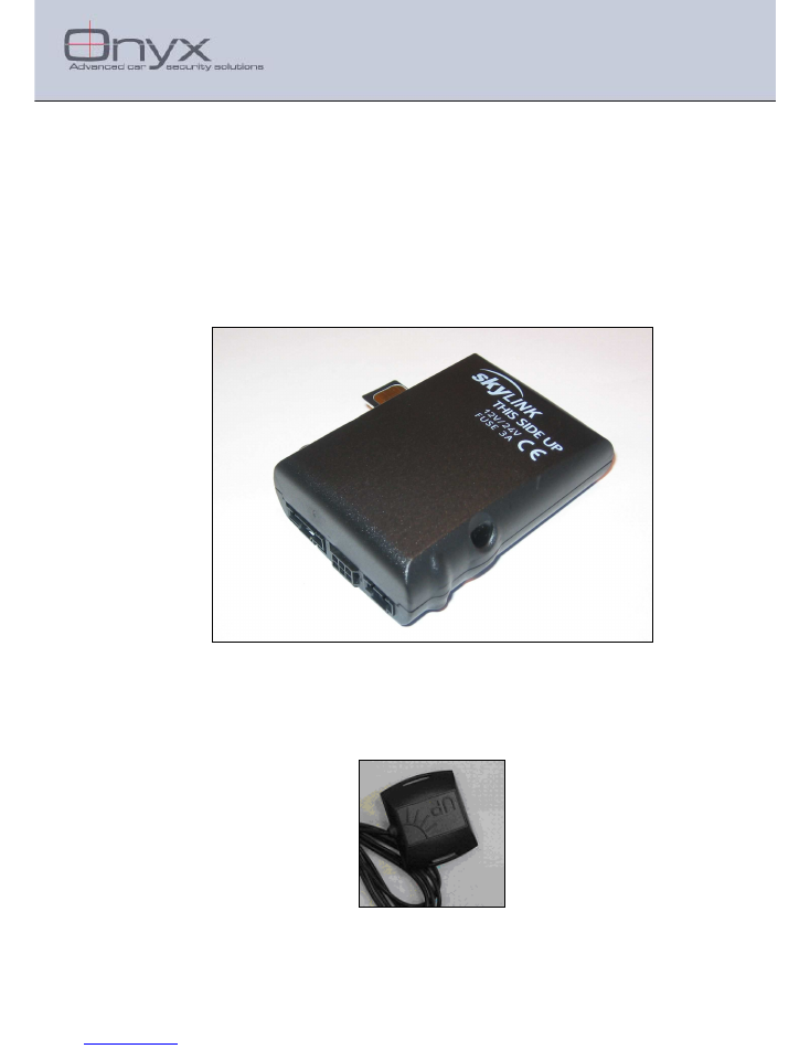
The EGPRS box holds the GPRS engine, internal antenna, backup battery with
charger and three external connectors. Shorter than 90mm and narrower than
65mm, it is very compact and easily assimilated and installed in the car
environment.
The shell which covers the unit is made of hardened plastic. The SIM socket is
present on the right long of the unit. Three connectors are located on the rear
side as illustrated below. The unit can be anchored using 2 niches, one on each
side of the unit.
Figure 3 - EGPRS module
2.4.2
GPS
The GPS module is provided with a plastic case and 4-wire cable ended with a
Molex 4-pin connector. The module size is 45x45mm and the on-top mounted
patch antenna is 25x25mm.
Figure 4 - GPS module
Onyx.
Advanced car security solutions
16 Shapira St. Rishon Le - Zion 75052, Israel
Tel: 972-3-9413313 ; Fax: 972-3-9413330
www.onyxtech.co.il ; info@onyxtech.co.il
Page 8 of 12 EGPRS Unit User Guide
2.4.3
Connectors, Inputs and Outputs
2.4.4
Connectors, Inputs and Outputs
The
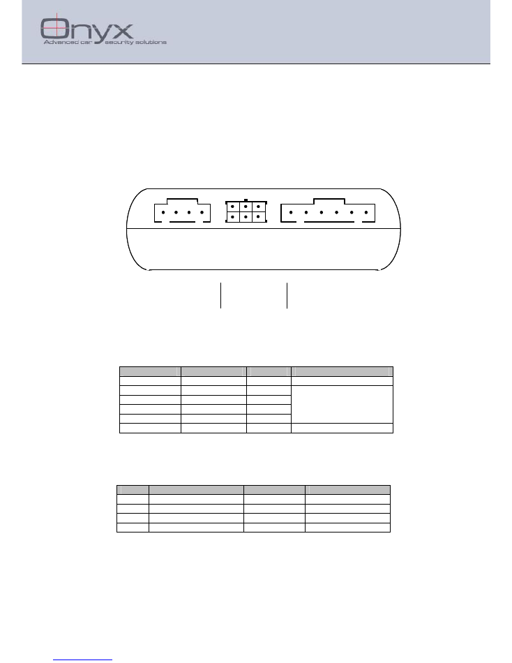
EGPRS unit has 3 connectors:
1. Molex 4-pin for GPS (if working with External GPS)
2. Microfit 06P for I/O interfacing (middle connector)
3. Molex 6-pin for power and communication (RS485).
The following diagram shows the structure of the connectors, the
numbers below the image are pin's number identification:
6 5 4 3 2 1
3 2 1
6 5 4
4 3 2 1
6 5 4 3 2 1
3 2 1
6 5 4
4 3 2 1
2.4.4.1 RS485 Connector - Description
The following figure illustrates the structure of the 6-pin connector used for
power supply and communication through RS485. The pinout is given below.
2.4.4.2 RS232 Connector (GPS) - Description
The EGPRS communicates with the GPS device over a RS-232 channel. The
pinout is given below.
Pin #
Signal
Color
Notes
1
GND
Black
2
+4.2 VDC
Red
3
Rx EGPRS
Gray
GPS to EGPRS
4
Tx EGPRS + Wakeup
Green
EGPRS to GPS
Pin #
Signal
Color
Notes
1
GND
Black
2
3
4
5
Not in Use
6
Vcc(12V/24V)
Red
Voltage level 9V to 36V

Onyx.
Advanced car security solutions
16 Shapira St. Rishon Le - Zion 75052, Israel
Tel: 972-3-9413313 ; Fax: 972-3-9413330
www.onyxtech.co.il ; info@onyxtech.co.il
Page 9 of 12 EGPRS Unit User Guide
2.4.4.3 Inputs Connector - Description
(HW version 0 analogs):
Pin#
Port Name
Type
Input
Wire
Functionality
Digit
al
Input
ID
Digital
Output
ID
Analog
ID
4
Port A
I/O
Pull Up
Purple
Digital Input or
Digital Output
1
1
-
1
Port B
Output
-
Gray
Digital Output (active low) -
2
-
5
Port C
Input
Pull Down
Blue
Digital Input or
VSS
2
-
-
6
Port D
Input
Pull Up
Green
Digital Input or
eNet or
Dallas
3
-
-
3
Port E
Input
Pull Up
Yellow
Digital Input
4
-
-
2
Port F
Input
Pull Down
Brown
Ignition only
-
-
-
(HW version 1 Analog):
Pin#
Port Name
Type
Input
Wire
Functionality
Digital
Input
ID
Digital
Output
ID
Analog
ID
4
Port A
I/O
Pull Up
Purple
Digital Input or
Digital Output or
Analog In (0-12)
1
1
3
1
Port B
Output
-
Gray
Digital Output (active low) -
2
-
5
Port C
Input
Pull Down
Blue
Digital Input or
VSS
2
-
-
6
Port D
Input
Pull Up
Green
Digital Input or
eNet or
Dallas
3
-
-
3
Port E
Input
Pull Up
Yellow
Digital Input
4
-
-
2
Port F
Input
Pull Down
Brown
Ignition only
-
-
-
(HW version 2 Analogs):
Pin#
Port Name
Type
Input
Wire
Functionality
Digital
Input
ID
Digital
Output
ID
Analog
ID
4
Port A
I/O
Pull Up
Purple
Digital Input or
Digital Output or
Analog In (0-12)
1
1
3
1
Port B
Output
-
Gray
Digital Output (active low)
or Dallas Out
-
2
-
5
Port C
Input
Pull Down
Blue
Digital Input or
VSS
2
-
-
6
Port D
Analog
Pull Up
Green
Analog In (0-5v)
3
-
4
3
Port E
Input
Pull Up
Yellow
Digital Input
Or
Dallas In
4
-
-
2
Port F
Input
Pull Down
Brown
Ignition only
-
-
-
Notes:
1. Inputs will have the
Input
value when no wire is connected (for example Port C will
be logical 0, and Port E will be logical 1).

Onyx.
Advanced car security solutions
16 Shapira St. Rishon Le - Zion 75052, Israel
Tel: 972-3-9413313 ; Fax: 972-3-9413330
www.onyxtech.co.il ; info@onyxtech.co.il
Page 10 of 12 EGPRS Unit User Guide
2.4.5
Electrical Specification
Nominal Input Voltage Level
12V /24V
Minimal Input Voltage Level
9 V
Maximal Input Voltage Level
36V
Current Consumption (12V)
Reception (SMS Mode)
11 mA
Reception (GPRS Mode)
17 mA
Transmission
200 mA
Current drain
Navigation
<45 mA
Powerdown*
<5 mA
Positive Spike Resistibility
+100 Volt for a period of 8 ms.
Negative Spike Resistibility
-100 Volt for a period of 8 ms
Backup Batteries
3 x AA NiMH, 750 mAH
Output Power Voltage
4.2 V
Current
100 mA max
Ripple
< 5 mV
2.4.6
Environment Condition
Storage Temperature
-40 to 85
°
C
Operating Temperature
-20 to 50
°
C
Max. Relative Humidity
90
±
5%
Acceleration
10 m/sec2
Vibration
Meets ISO 16750 part 3
Mechanical shock
Meets ISO 16750 part 3
Car Voltage
Meets ISO 16750 part 2
2.4.7
Size and Weight
Size: 6x8.5 cm; 2.36x3.35 in.
Weight (Excluding the GPS module) 125g
Onyx.
Advanced car security solutions
16 Shapira St. Rishon Le - Zion 75052, Israel
Tel: 972-3-9413313 ; Fax: 972-3-9413330
www.onyxtech.co.il ; info@onyxtech.co.il
Page 11 of 12 EGPRS Unit User Guide
3
Installation Guide
3.1
EGPRS Vehicle Installation
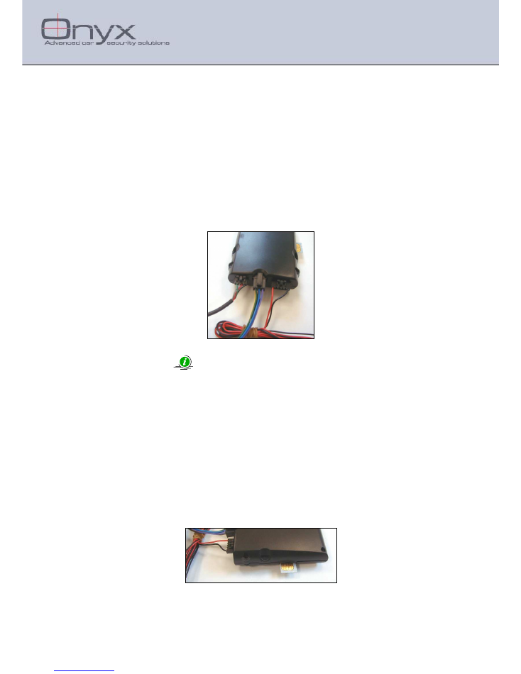
1. Make sure a SIM card is inserted into the unit.
2. Connect the black wire to a permanent GND.
3. Connect the red wire to a permanent 12V or 24V source through a 3A fuse.
Note: Suitable approved slow-blow fuse 3A should be provided by the End
User.
4. When applicable, connect the brown wire of the I/O harness to the Ignition switch
(ignition on should supply 12/24V to the brown wire).
5. Connect the GPS connector to the unit if a GPS is installed.
Figure 5 - Up View
3.1.1
Attention:
The EGPRS unit must not be installed next to heat sources or moving parts.
The installation position must be water proof.
The EGPRS unit should be installed in the cabin or the trunk.
The EGPRS unit should not be installed behind the fuse box.
The antenna side of the EGPRS unit should be facing upwards if possible,
Never install the EGPRS unit with the antenna side next to metal.
The EGPRS must be installed by qualified service personnel only.
3.1.2
SIM Card
Insert the SIM card as shown in the following picture:
Figure 6 - SIM Card insertion
Onyx.
Advanced car security solutions
16 Shapira St. Rishon Le - Zion 75052, Israel
Tel: 972-3-9413313 ; Fax: 972-3-9413330
www.onyxtech.co.il ; info@onyxtech.co.il
Page 12 of 12 EGPRS Unit User Guide
3.1.3
GPS Installation
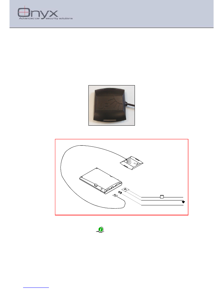
The GPS module should be installed in a position which will allow it to "see the
sky" as clearly as possible
The GPS module must not be installed near the front window in cars with front
window.
The GPS module must be installed with the side marked with "UP" being the
side facing upwards.
Figure 7 - GPS Module
3.1.4
Installation diagram
FUSE
5 A
+12 V
GND
+ 15
+ 30
SKYLINK
GPS
IGN SW
RED
BLACK
BRAWN
3.1.5
Battery replacement:
Caution: Risk of explosion if battery is replaced by an incorrect type.
Dispose of used batteries according to instructions.