Full Text Searchable PDF User Manual

NOUVAG AG
MD 10
No. 31820 22/07
1
TABLE OF CONTENTS
1
Description
2
1.1
Operations and functions
2
1.2
Technical Data
2
1.3
Operating Environment
2
1.4
Transport and Storage Environment
2
1.5
Symbols
2
2
Safety measures
3
3
System Assembly
4
4
Operation
4
4.1
Set-up
4
4.2
Tubing assembly-Internal irrigation
5
4.3
Tubing assembly–External irrigation
5
4.4
Tubing assembly-combined
5
5
Operation
6
5.1
Starting the MD 10
6
5.2
Keyboard
6
5.3
Setting the revolutions-
6
5.4
Setting the output of the irrigation pump
7
5.5
Operation with vario-pedal
7
5.6
Setting the torque limiter AL (Automatic Limiter)
8
5.7
Setting the torque limiter AS (Automatic Stopper)
8
5.8
Memory
8
6
Disinfection, Cleaning and Sterilization
9
6.1
Control unit and foot control
9
6.2
Electronicmotor 31ESS
9
6.3
Tubing set Nr. 1706
9
6.4
Y-Connector
9
7
Troubleshooting
10
8
Replacement parts and numbers
10
9
Disposal
10
MD 10
NOUVAG AG
2
No. 31820 22/07
KB 1min on /
3min off
1 Description
1.1 Operations and functions
The MD10 is used in Implantology and microsurgery. The unit is designed for drilling, screwing and
sawing. A built-in irrigation system minimizes the heat generation of the rotating instruments in order to
reduce infections that can cause tissue damage.
1.2 Technical Data
Voltage: .................................................................... changeable: 230 V
∼
/ 50-60 Hz or115 V
∼
/ 50-60 Hz
Power: ........................................................................................................................................... 130 VA
Application of part: ...................................................................................................................... Type BF
Protection level: ............................................................................................................................ Class 1
Motor speed: ................................................................................................................ 500 – 40,000 rpm
Max. torque: ................................................................................................................................. 10 Ncm
Dimensions (WxHxD): ............................................................................................. 120 x 190 x 250 mm
Net weight: ......................................................................................................................................... 3 kg
1.3 Operating Environment
Relative Humidity: ....................... max. 80%
Temperature: ..............................10 to 40°C
Pressure: ........................... 800 to 1060hPa
1.4 Transport and Storage Environment
Relative Humidity:............................. max. 90%
Temperature:..................................... 0 to 60°C
Pressure: .................................700 to 1060hPa
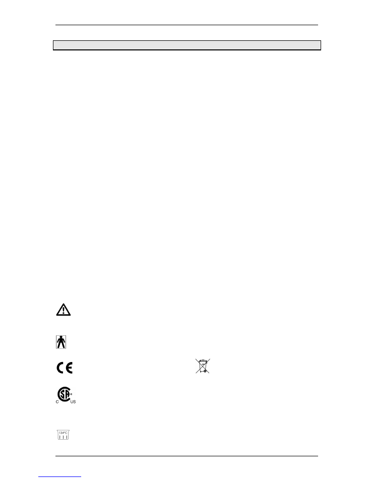
1.5 Symbols
: Attention accompanying
documents
: Application of part type BF
1275 : Conforms to EU standards
: Certified by Canadian Standards
Association (CSA) for Canada and
USA
: Autoclavable at max. 134°C
IP68
: Watertight foot control
: Electronic motor short operation:
1min on 3min off
: Old electrical and electronic
equipment must be disposed
separately and may not be
included in regular domestic
waste.
NOUVAG AG
MD 10
No. 31820 22/07
3
2 Safety measures
Your safety, the safety of your team, and, it goes without saying, the safety of your patients is for Nouvag
AG the first priority. It is therefore vital that the following measures be strictly observed:
Important:
•
The MD 10 should be operated by qualified personnel only!
•
Responsibility for the use of sub-units, accessories, parts or assemblies from
other manufacturers rests solely with the user!
•
Repairs are to be carried out by authorized NOUVAG service technicians only!
•
Nouvag AG cannot be held liable for any malfunction of the MD 10, or
performance failure and/or its designed or desired utility, nor can Nouvag AG
be held liable for any injuries to persons or animals, in any case when the MD
10 is miss-used or not operated, applied or maintained in strict accordance with
the user/owner instructions set out in the operating manual. In the event of any
doubt or question, the user is to contact Nouvag AG or its lawful representative
for clarification or assistance!
In Operation:
•
The unit will be not supplied in a sterile condition!
•
Do not attach the handpiece and contra angle while the motor is running!
•
To avoid danger, do not grab running burr or drill!
•
To avoid damage of the instruments, do not handle the clamping mechanism,
while the handpiece or contra angle are in operation!
MD 10
NOUVAG AG
4
No. 31820 22/07
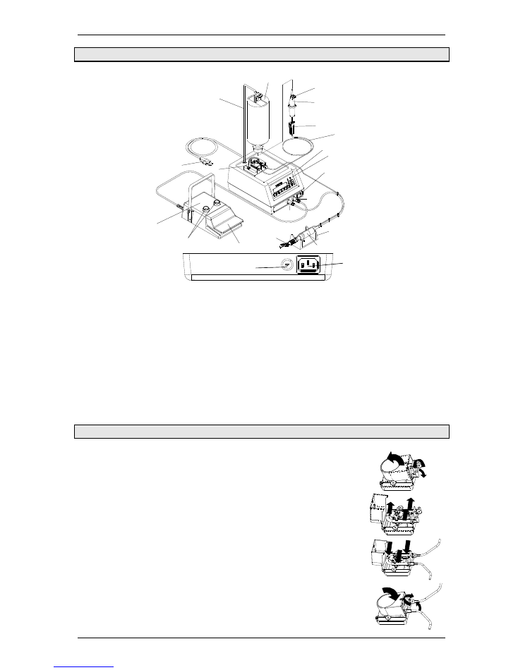
3 System Assembly
11
5
8
18
17
19
4
13
3
1
2
6
7
9
10
12
14
15
16
21
20
1.
Control unit
2.
Keyboard panel
3.
Mains switch “ON / OFF“
4.
Pedal socket “FOOT SWITCH”
5.
Motor socket “MOTOR“
6.
Electronicmotor
7.
Handpiece support
8.
Contra angle (not included)
9.
Tubing set
10.
Cooling fluid flask
11.
Hanger rod for liquid flask
12.
Pump
13.
Mains cable
14.
Foot control (IP68)
15.
Switch for Pump and Forw/Rev
16.
Foot plate
17.
Tube clamp
18.
Drip chamber
19.
Air valve
20.
Mains cable socket
21.
Voltage switch
4 Operation
4.1 Set-up
1) Insert solution hanger in support on panel of control unit.
2) Insert electronicmotor plug into motor socket “MOTOR“.
3) Insert pedal plug into pedal socket„FOOT SWITCH“.
4) Attach contra angle to electronicmotor.
→
see row of pictures right:
5) Loosen and lift screw latch from pump lid.
6) Open lid forward.
7) Remove demonstration tube.
8) Insert tube set.
9) Close pump lid, lower screw latch and close.
NOUVAG AG
MD 10
No. 31820 22/07
5
Insure that „pressure“ tube runs to irrigation needle, and „suction“ tube runs to
solution bottle!
10) Insert tube needle and hang cooling flask on hanger rod.
11) Open tube clamp.
12) Open air valve of the drip chamber.
13) Connect the mains cable into the electrical outlet.
Check for correct operation voltage and verify mains voltage output!
230
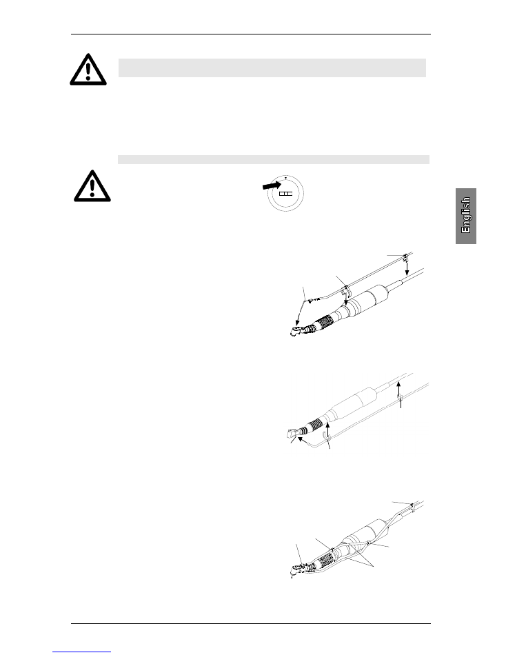
4.2 Tubing assembly-Internal irrigation
1) Insert internal irrigation needle (1) into the end of the
tubing.
2) Attach clip (2 & 3) to irrigation tubing.
3) Insert irrigation needle into contra angle.
4) Attach clip to contra angle and to motor cable.
5) When necessary, attach additional clips to motor cable.
1
2
3
4.3 Tubing assembly–External irrigation
1) Attach clip (1 & 2) to irrigation tubing.
2) Connect piece of tubing to irrigation needle (3).
3) Attach clip to contra angle and to motor cable.
4) When necessary, attach additional clips to motor
cable.
3
1
2
4.4 Tubing assembly-combined
1) Attach Y-connector (1) to the end of the tubing.
2) Attach two 16cm pieces of tubing (2) to Y-connector.
3) For internal irrigation, connect first tubing piece to
irrigation needle (3).
4) Attach clips (4 & 5) to irrigation tubing.
5) Attach irrigation tubing with clip to contra angle and to
motor cable.
6) Insert irrigation needle into contra angle.
7) Connect second tubing piece with external irrigation.
8) When necessary, attach additional clips to motor cable.
4
5
1
2
3
MD 10
NOUVAG AG
6
No. 31820 22/07
5 Operation
5.1 Starting the MD 10
Press green “ON/OFF“ switch.
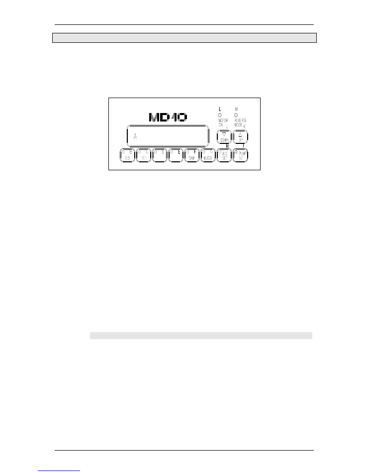
5.2 Keyboard
A) Display:
Indication of the revolutions (speed), torque or pump speed.
B) Multiplying key “1:5” (for contra angle 1:5):
Speed: 2,500 – 200,000 rpm
Torque: 1, 2 Ncm
C) Multiplying key “1:1” (for contra angle 1:1):
Speed: 500 – 40,000 rpm
Torque: 1, 2, 3, 4, 5, 6, 7, 8, 9, 10 Ncm
D) Reduction “16:1” (for contra angle 16:1):
Speed: 30 – 2,500 rpm
Torque: 5, 7, 10, 12, 15, 17, 20, 25, 30, 35 Ncm
E) Reduction “32:1” (for contra angle 32:1):
Speed: 15 – 1,250 rpm
Torque: 10, 15, 20, 25, 30, 35, 40, 45, 50, 55 Ncm
F) Fixed key “SAW” (for Nouvag saws):
Speed: 14,000 rpm
Torque: 10 Ncm
G) Fixed key “MUCO” (for Nouvag Mucotome):
Speed: 8,000 rpm
Torque: 10 Ncm
H) Key “ATC SET”:
Press key “ATC SET” to adjust the torque limiter AL or AS.
I)
Key “PUMP SET”:
Press key “PUMP SET” to adjust the pump speed.
J) Taste “DOWN”:
To decrease the speed, torque and pump.
K) Taste “UP”:
To increase the speed, torque and pump.
L) Light “MOTOR ON”:
The green light indicates that the electronicmotor is switched on.
M) Light “REVERSE MODE”:
The green light indicates that the electronicmotor operates in reverse and a warning tone will sound.
5.3 Setting the revolutions-
1) Press the appropriate reduction or multiplying key (for example key “32:1” for contra angle 32:1).
The green light on key B) to I) illuminates, when the key is activated.
16:1
32:1
NOUVAG AG
MD 10
No. 31820 22/07
7
2) Press keys “UP” or “DOWN” to select the desired speed.
With the keys “SAW“ (for Nouvag-saws) and “MUCO“ (for Nouvag-Mucotome) the corresponding fixed
speed and torque values can be adjusted.
5.4 Setting the output of the irrigation pump
The output of the irrigation pump can be selected from 1 to 10 levels.
1) Press key “PUMP SET” and in the display appears for example, pump selection [P 6].
2) Press keys “UP” and “DOWN” to select the desired pump speed.
3) Press key “PUMP SET” or wait 3 seconds until the revolutions appear automatically in the display.
5.5 Operation with vario-pedal
Key “PUMP“:
To turn the pump on and off (see light “PUMP SET“)
Key “FORW / REV“:
To adjust the direction of rotation of the motor (see light “REVERSE MODE“)
Foot plate:
Push foot plate down to start pump action and to vary the motor speed.
Foot plate ...
Motor:
Pump:
... not pressed
Motor off
Pump off
... lightly pressed
Motor runs slowly
Pump on, if “PUMP“ is pressed
(speed as indicated by setting on
control unit)
... fully pressed
Motor speed max.(as indicated
by setting on control unit)
Pump on, if “PUMP“ is pressed
(speed as indicated by setting on
control unit)
The reduction or multiplication on the keyboard panel has to be according to the
reduction or multiplication of the contra angle, otherwise the device will indicate
an incorrect revolution.
Caution: for safety use the unit with foot control only!

MD 10
NOUVAG AG
8
No. 31820 22/07
5.6 Setting the torque limiter AL (Automatic Limiter)
The automatic limiter (AL) limits the torque level applied to the instrument. The AL-modus is used for
drilling into the bone, in order to allow the electronicmotor to develop enough power, so the instrument
can have a good drive in hard bones, as well. The speed in the instrument is hold constantly until the
selected setting is reached. If the load in the instrument over the adjusted limiter increases, the speed
will drop to zero. The power in the instrument remains. If the load in the instrument over the adjusted
limiter decreases, the speed will increase again.
All torque values are shown in Ncm (for example a setting of [AL 20]
→
indicates that the instrument
can be loaded to maximum of max. 20 Ncm before rotations stops).
Adjusting the AL:
1) Press the “ATC” key. In the display appears the torque mode set (for example [AL 20]).
2) Pressing the keys “UP” and “DOWN” will increase and decrease the torque level respectively.
3) Press “ATC SET” or wait for 3 seconds until the speed appears automatically in the display.
5.7 Setting the torque limiter AS (Automatic Stopper)
The function AS limits the torque in the instrument. The AS operates like a torque wrench for tightening
implants and abutments. The electronicmotor stops immediately when the preselected torque is
achieved and in the display appears the selected torque, for example [AS 40]. The electronicmotor
does not generate power anymore. To restart the electronicmotor, release briefly the foot plate and
press it again.
All torque values are shown in Ncm (for example a setting of [AS 20]
→
indicates that the instrument
can be loaded to maximum of max. 20 Ncm.
Setting the AS:
1) Press reduction key “16:1” or “32:1”.
2) Adjust the speed between 30 and 150 rpm and 15 and 75 rpm respectively.
3) Press key “ATC SET” . In the display appears the torque selection (for example [AS 20]).
4) Press keys “UP” and “DOWN” to select the desired torque values.
5) Press the key “ATC SET” or wait for 3 seconds until the revolutions appear automatically in the
display.
5.8 Memory
Once programmed, the preselected speed, torque and value setting will remain stored in memory, even
when the motor is turned off.
If the display says [AS.....] :
Press key “DOWN” until [AL.....] appears in the display.
When the AL-Modus is activated, the green light on the “ATC SET” key does not
illuminate.
The function AS is activated in the reductions 16:1 and 32:1 only, and up to 150
rpm and 75 rpm respectively! For other reduction or multiplication use function
AL.
If the display says [AL.....]:
Press key “UP” until [AS.....] appears in the display.
When the AS-Modus is activated, the green light on the “ATC SET” illuminates.
NOUVAG AG
MD 10
No. 31820 22/07
9
6 Disinfection, Cleaning and Sterilization
Please pay attention to the following important points for the maintenance of the material:
•
Clean, disinfect and sterilize the device and components after each use.
•
Do not use dissolving agents for cleaning.
•
Autoclave material in transparent packaging.
•
Do not fill the sterilization bag more than 80%.
•
Autoclave material at maximum 134°C.
•
Sterilized material should be stored and tagged with sterilization date,
6.1 Control unit and foot control
The control unit and the foot control do not come in contact with patients. Clean the surface of the unit
only, do not use harsh cleaners or solvents for cleaning. Use 80% ethyl alcohol or microbiologically
effective disinfectants. The control unit face is sealed and washable.
6.2 Electronicmotor 31ESS
•
To avoid breakage, do not bend motor cable!
•
Do not clean the electronicmotor with compressed air!
•
Clean, disinfect and sterilize the electronicmotor after each use!
•
Autoclaving the electronicmotor without packing it into a transparent bag may
seriously damage it!
•
After autoclaving, allow electronicmotor to dry for one hour at room
temperature.
1) The electronicmotor, cable and plug should be cleaned after each use to prevent the build up of
deposits and debris that can destroy it, if not removed. Wipe it with a clean cloth dampened with
disinfectant solution.
2) Spray the motor interior with Nou-Clean - spray.( See spray can instructions).
3) Pack Motor in transparent bag (see DIN 58953).
4) After packing motor and cable, autoclave it at maximum 134°C .
After autoclaving, allow electronicmotor to dry for one hour at room temperature.
6.3 Tubing set Nr. 1706
Disposable tubing set Nr. 1706can not be sterilized!
6.4 Y-Connector
After use, flush the saline residue out of the Y-Connector with distilled water for
approximately 20 seconds with distilled water!
1) Flush the Y-Connector with connected contra angle with distilled water for approximately 20
seconds.
2) Remove the tubings from the Y-Connector.
3) Pack the Y-Connecotor in a transparent bag and sterilize the pack in an autoclave at max. 134°C.
MD 10
NOUVAG AG
10
No. 31820 22/07
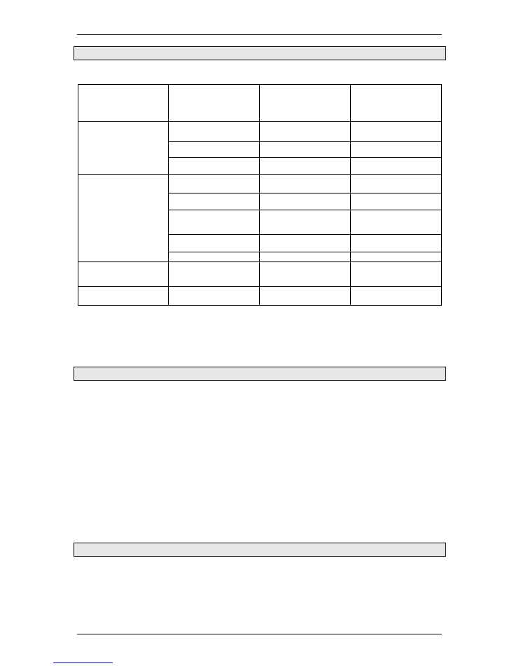
7 Troubleshooting
Problem:
Cause:
Solution:
Refer:operating
Manual:
Device does not
operate at all
Control unit not turned on
Turn main switch
“ON/OFF“ON
3
System Assembly
Wrong operating voltage
Check mains voltage
output
1.2
Technical Data
Mains not connected
Connect mains to control
unit
3
System Assembly
No coolant in the
instrument
Irrigation pump not turned
ON
Turn the irrigation pump
ON
5.5
Operation with vario-
pedal
Tubing set not mounted
properly
Mount tubing properly (pay
attention to direction!)
4.1
Set-up
Tubing set is glued
together/coated with
deposit
Exchange tubing
4
Operation
Cooling fluid flask
not ventilated
Open air filter on drip
chamber
3
System Assembly
Tubing set is dripping
Exchange tubing set
4.1
Set-up
[ HOT ] appears in
display
Electronicmotor is getting
too hot
Turn off the unit, wait for
10 minutes, turn on the
unit again
Foot control fails to
function
Foot control not connected
Plug foot control into
control unit
4.1
Set-up
In the event a problem cannot be solved, contact dealer or authorized service technicians, as listed on
the last page of your Operating Instruction Manual.
8 Replacement parts and numbers
Accesories
Art.-Nr
Clip Set motor cable (10 pcs.) ............................................................................................................1873
Clip Set contra angle (3 pcs.) .............................................................................................................1881
Tubing (16cm) for Y-Connector ..........................................................................................................1773
Disposable tubing set, standard, sterile..............................................................................................1706
Y-Connetor .........................................................................................................................................1777
Cooling fluid flask, 0.9% NaCl, 1l........................................................................................................1707
Nou-Clean; Cleaning spray.................................................................................................................1984
Spray nozzle attachment E-coupling, for surgery instruments ...........................................................1958
Spray nozzle attachment, for electronicmotor ....................................................................................1942
For ordering other parts, our customer service personnel are pleased to assist
9 Disposal
Disposal of device, components and accessories must strictly conform to local laws and regulations as
set out by the relevant authorities.
With regard to the preservation of the environment old equipment may be returned to the distributor or
manufacturer.