Full Text Searchable PDF User Manual

Full Manual
2
VERSION ISSUED
Date Issued
Version
No.
Description
Revised
By
Approved
By
3
rd
April 2008
1.8.0.0
7
th
April 2008
1.10.0
Add Toledo
Remove Avery, JAD
NW
8
th
April 2008
1.10.1
Updated section 5.
Removed switch
0,4,5,6 and updated
6
DW
DW
8
th
May 2008
1.10.2
Updated section 5.
add switch 6
–
Mettler Toledo
DW
DW
2
nd
June 2008
1.10.3
Updated section 5
DW
DW
26
th
August 2008
1.11.0
Updated Section 5.
Added 14 (E)
JAC320 FV Format
DW
DW
30
th
Oct 2008
1.12.0
Update Section 5.
to add Scale
formats 17 & 18
DW
DW
24
th
June 2009
1.15.0
Update Section 5 to
add Scale format 19
DW
DW
25
th
March 2010
1.19.0
Updated Rinstrum
5230 Format
DW
DW
9
th
August 2010
1.21.0
Added Format 20
for JAC350 Axle
Weighing
DW
DW
13
th
August 2010
1.22.0
Power up without
going through
parameters etc
(Configurable)
DW
DW
8
th
March 2011
1.23.0
Added Format 21
for Command Batch
System
DW
DW

Full Manual
3
INDEX
VERSION ISSUED
2
1
.
GENERAL INSTRUCTIONS
4
1.1
Working Environment
4
1.2 The front plate
4
2
.
INSTALLATIONS
5
2.1 Configuration of data communication
5
2.2 Connection Cables
6
2.3 On-Site Installation
8
3
.
WORKING MODE
9
4. MULTIPLE DISPLAY COMMUNICATIONS
12
5. CONFIGURATION
13
6. SERIAL COMMUNICATIONS PARAMETERS
14
7. UNITS OF MEASURE
14
8. EXPLANATION OF PC MODE 1
15
9. POWERUP WITH NO PARAMETERS DISPLAYED
15
Full Manual
4
1
.
GENERAL INSTRUCTIONS
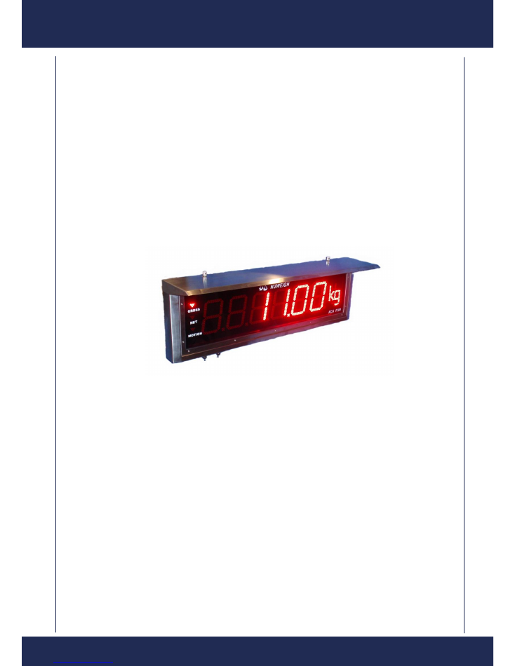
The KCA1100 Series LED remote displays provide high-visibility, six-digit display capability for
use in a wide variety of applications. This manual provides general installation and configuration
instructions for the KCA1100.
The waterproof enclosure of stainless steel enables the KCA1100 to work in rug environment. The
detachable sunlight shelter makes the display suitable for both indoor and outdoor uses.
The specially designed brackets make it possible and easy to install the KCA1100 on different
places such as the ceiling, the wall and a pole etc.
W a r n i n g : So m e p ro c e d u r e s d e s c ri b e d i n t h i s m a n u a l r e q u i re w o rk i n s i d e
t h e d i s p l a y e n c l o s u r e . T h e s e p ro c e d u r e s a r e t o b e p e rf o rm e d b y q u a l i f i e d
s e rv i c e p e r s o n o n l y .
1.1 WORKING ENVIRONMENT
1 . T e m p e r a t u r e
:
- 1 0 ~ 4 0
℃
2 . H u m i d it y
:
9 5 % R . H
3 . P o w e r s u p p l y
:
A C 1 1 0 V ~2 4 0 V( + - 1 0 % ) 5 0 - 6 0 H z
4 . D a t a i n p u t
:
R S 2 3 2 / 4 8 5 , 0 - 2 0 m Ac u r r e n t l o o p , a n d
S yn c h r o n o u s s e r i a l d a t a in p u t .
6 . I n s t a l l a t i o n D im e n s i o n s
:
9 2 2 m m ×2 4 0 m m ×6 1 m m ( wi t h o u t s u n l i g h t s h e lt e r )
9 2 6 m m ×2 4 2 m m ×2 0 0 m m ( wi t h s u n l i g h t s h e lt e r )
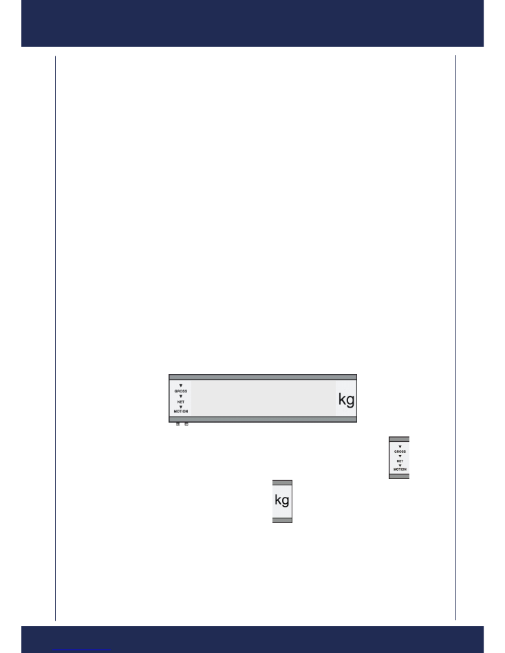
1.2 THE FRONT PLATE
T h e f r o n t p la t e ( T h e d a r k b la c k p a r t c o n s is t s o f L ED s
)
GROSS:
When the LED’s above light, the following six digits show gross weight.
N ET :
When enabled, the following six digits show net weight.
MOTION:
When this indicator lights, it means the current load is not s t a b l e .
U n i t s i n d i c a t o r s :
t
—— Meas ur ing in tonnes .
k g
—— Meas uring in k ilogr am s.
8. 8. 8. 8 .8 .8

Full Manual
5
2
.
INSTALLATIONS
2.1 CONFIGURATION OF DATA COMMUNICATION
K C A1 1 0 0
h a s t h r e e k in d s o f c o m m u n ic a t i o n :
R S 2 3 2 / 4 8 5 , 0
~
2 0 m A c u rr e n t l o o p a n d s e r i a l
s y n c h r o n o u s p r o t o c o l s .
O p e n t h e c o v e r p l a t e a t t h e le f t b o t t o m o f
K C A1 1 0 0
a n d p u l l d o w n t h e b o a r d s h o w n a s l e f t
f ig u r e . Yo u c a n c o n f i g u r e t h e c o m m u n ic a t i o n
p r o t o c o ls b y c h a n g in g d i p s w i t c h e s SW 1 , J P 1
a n d J P 2 .
1 . R S2 3 2 P ro t o c o l :
(
f a c t o r y d e f a u lt p r o t o c o l
)
S e t
SW 1 ( r e d ) , J P1 a n d J P 2
a s f o r R S 2 3 2
c o m m u n ic a t i o n .
2 . R S4 8 5
Pr o t o c o l :
S e t
SW 1 ( r e d ) J P 1 a n d J P 2
a s f o r R S4 8 5
c o m m u n ic a t i o n .
3 . 0
~
2 0 m AC u r re n t L o o p :
S e t t h e SW 1 a s f o r
0
~
2 0 m A C u r r e n t L o o p
c o m m u n ic a t i o n .
Pl e a s e n o t e t h a t w h e n u s i n g 0 - 2 0 m A c u r r e n t l o o p c o m m u n i c a t i o n p ro t o c o l ,
y o u n e e d t o p o w e r o n t h e K C A1 1 0 0 f i r s t a n d t h e n p o w e r o n t h e i n d i c a t o r
c o n n e c t e d t o t h e d i s p l a y .
4 . S y n c h ro n o u s Se r i a l C o m m u n i c a t i o n :
S e t t h e SW 1
(
B l u e
)
a s f o r S yn c h r o n o u s Se r i a l
c o m m u n ic a t i o n .
N o t e : P l e a s e r e s e t t h e re m o t e d i s p l a y b y p o w e r o f f a n d o n w h e n e v e r t h e
c o m m u n i c a t i o n p r o t o c o l o r b a u d r a t e w a s c h a n g e d t o m a k e yo u r n e w
c o n f i g u r a t i o n e n a b l e d .
Full Manual
6
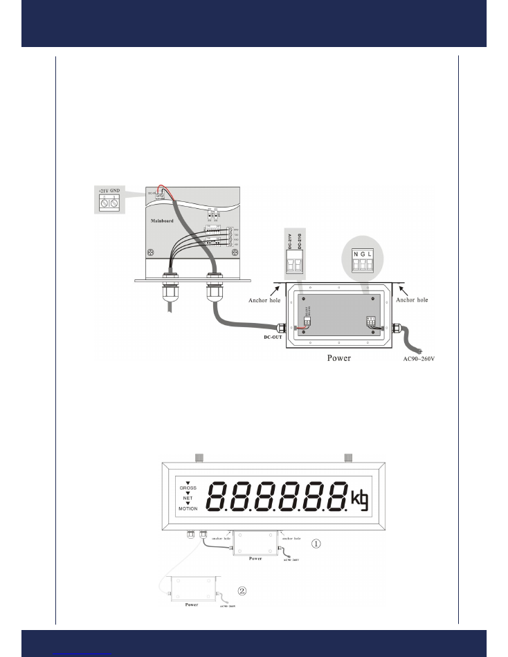
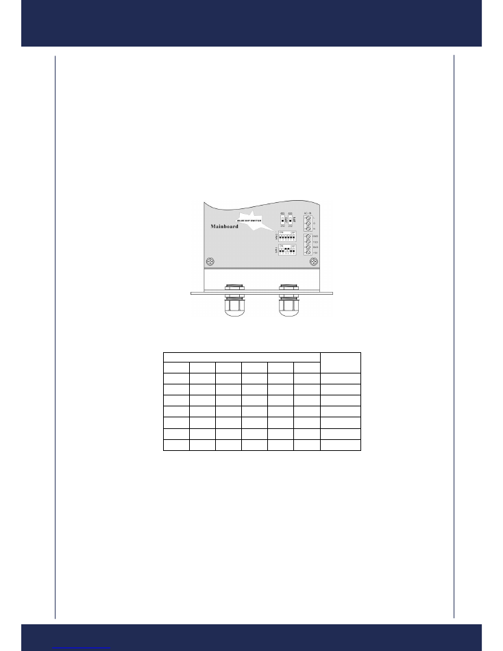
2.2 CONNECTION CABLES
K C A1 1 0 0
h a s t w o c o n n e c t io n c a b le s a s s h o w n b e l o w . T h e l e f t o n e ( 4 P t e r m in a l)
is f o r d a t a i n p u t a n d t h e r ig h t o n e ( 2 P t e r m i n a l) is f o r p o w e r s u p p l y.
A ls o , i n t h e p o w e r , yo u m u s t p a y a t t e n t i o n t o t h e c o n n e c t io n s o f A C - I N ( 3 P
t e r m i n a l) a n d D C - O U T ( 2 P t e r m in a l) w h ic h c o n n e c t s w i t h D C - I N ( 2 P t e r m in a l ) o f
t h e m a in b o a r d . T h e p i c t u r e is a s f o l l o ws .
Warning
:
When connecting to KCA1100 system, please be caution with power
polarity. We are not responsible for any damage caused by incorrect power polarity
connection.
T h e r e a re t w o p l a c e m e n t m o d e s :
( 1 ) Y o u c a n f i x t h e p o w e r o n t h i s d i s p l a y a n d w e h a v e t r e p a n n e d t w o
h o l e s u n d e r i t . J u s t s c r e w d o w n b y s c re w d ri v e r . P i c t u re
①
i s a s f o l l o w s .
( 2 ) Y o u c a n a l s o p l a c e t h e p o w e r w h e r e y o u w a n t . P i c t u r e
②
i s a s
f o l l o w s .
Full Manual
7
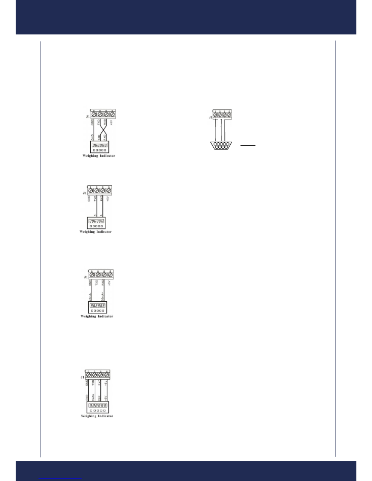
D a t a I n p u t C a b l e :
T h is is a 4 - w ir e c a b l e , a n d t h e c o n n e c t i o n is d if f e r e n t f o r d if f e r e n t
c o m m u n ic a t i o n p r o t o c o ls
:
1
)
F o r R S 2 3 2 ,
t h e c o n n e c t i o n b e t w e e n t h e d is p l a y a n d a n i n d ic a t o r o r P C is
a s d e p ic t e d a s b e l o w
:
2
)
F o r R S4 8 5 , t h e c o n n e c t i o n b e t w e e n t h e d i s p l a y a n d a n i n d i c a t o r i s a s
d e p i c t e d a s b e l o w
:
3
)
F o r 0
~
2 0 m AC u r r e n t L o o p ,
t h e c o n n e c t i o n is a s b e lo w .
4
)
F o r S yn c h ro n o u s S e r i a l ,
t h e c o n n e c t i o n is a s :
DB9 connection for
PC connection
5 4 3 2 1
9 8 7 6
TX
D
G
N
D
R
XD
+5V
Full Manual
8
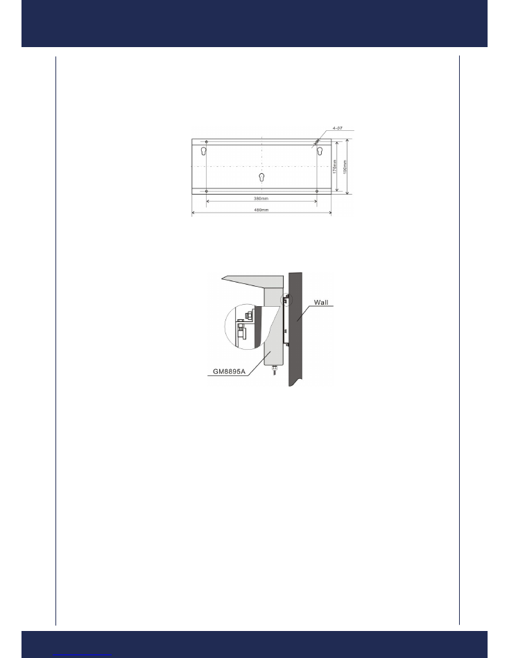
2.3 ON-SITE INSTALLATION
K C A1 1 0 0
r e m o t e d is p la y c a n b e in s t a l l e d o n a w a l l, a p o l e a n d h a n g f r om
c e il i n g . T h e in s t a l l a t i o n d im e n s io n s a r e a s :
K C A1 1 0 0 I
n s t a l l a t i o n D im e n s i o n s
T h e M
6 dilatant’s scr ews are suggested if you want to ins tall the KCA1100 to
t h e w a l l . P l e a s e r e f e r t o t h e s u g g e s t e d i n s t a l la t io n e x a m p l e a s f o ll o ws .
Full Manual
9
3
.
WORKING MODE
W he n t h e
K C A1 1 0 0
is p o w e r e d o n , it e n t e r s s e lf t e s t m o d e .
T h is is t h e S o f t w a r e v e r s io n .
T h is is t h e b a n d r a t e ( 1 2 0 0 / 2 4 0 0 / 4 8 0 0 / 9 6 0 0 / 1 7 2 0 0 ) .
T h is is t h e p a r i t y.
T h is t h e d a t a b i t s .
T h is is t h e c o n f ig u r e d f o r m a t . R e f e r t o T a b l e # 1
F
– I . 5 . O . O
b a u d
1 2 0 0
P A r - n
d b - 8
Par-N = no parity
Par-E = even parity
Par-0 = odd parity
Db-8 = 8 data bits
Db-7 = 7 data bits
S c - 9
8 . 8 . 8 . 8 . 8
.8

Full Manual
10
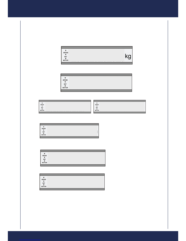
I f
t h e
K C A1 1 0 0
is c o n n e c t e d a n d c o n f i g u r e d c o r r e c t l y, i t w il l d i s p la y t h e d a t a
c o m in g f r o m t h e i n d ic a t o r a b o u t 5 ~ 1 5 s e c o n d s a f t e r s e lf t e s t .
I f t h e r e is a n yt h in g w r o n g w i t h c o n n e c t io n t o t h e i n d ic a t o r o r wr o n g d a t a f r o m
the indic ator , the dis pla y will dis pla y ― Err - to ‖ .
If the data is negative, the left m ost digit will be ―
-
‖.
I f t h e d is p l a y
s how― Err -Ur‖, that m eans data under r ange .
I f t h e d is p l a y s h o w s E r r - O r , t h a t m e a n s d a t a o v e r r a n g e .
kg
E r r - t 0
kg
E r r - U r
E r r - 0 r
6 4 1 2 . 5
8 8 9 . 5
Full Manual
11
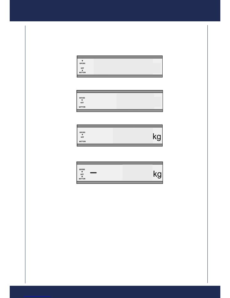
E x a m p l e s o f d i s p l a y i n g d a t a :
1 ) G r o s s w e ig h t , U n s t a b l e , I n p u t D a t a =
6 4 1 2 . 5
k g
:
2 ) N e t w e i g h , S t a b l e , I n p u t d a t a =
3 6 4
k g
:
3
)
N e t W e ig h t , S t a b l e , I n p u t D a t a =
1 9 8 0 k g
:
4
)
N e t W e ig h t , U n s t a b l e , I n p u t d a t a =
- 7 . 3 k g
kg
kg
6 4 1 2 . 5
3 6 4
1 9 8 0
7 . 3
Full Manual
12
4. MULTIPLE DISPLAY COMMUNICATIONS
This feature is an optional function of KCA1100 Remote Display. Please note that if you need this
function, you need to inform our company you’re your purchase order to make sure this optional
function is installed in the factory.
With this function, you can send and display different message onto multiple KCA1100 Remote
Displays that are linked with one cable.
4.1 Settings of SW2
For multiple displaying, please set the SW2 as:
SW2
I D
1
2
3
4
5
6
O F F O F F O F F O F F O F F O F F
* **
O F F O F F O F F O F F O F F
O N
0 1
O F F O F F O F F O F F
O N
O F F
0 2
O F F O F F O F F O F F
O N
O N
0 3
…… …… …… …… …… ……
……
O N
O N
O N
O N
O N
O F F
6 2
O N
O N
O N
O N
O N
O N
* **
Here, the ID can be coded from 01 to 62. When set to ―***‖ (all ON or all OFF), it disables Multiple
Display function and returns to normal working mode.

Full Manual
13
5. CONFIGURATION
Scale selection is performed by selecting various positions on the rotary switch (S2).
Table #1
Scale
Format
Switch
Position
J3 On/Off
Brand
Format
Notes
1
1
OFF
PC Format
2
2
OFF
Nuweigh
JAC101 AND 151/301
3
3
OFF
Nuweigh
JAC320 & Nuweigh
JAC330
Requires SB-400 Format
5
5
OFF
Mettler Toledo
Standard Continuous
Disable Checksum
Character
7
7
OFF
Gedge
C2 Format
Bd = 06
Be = 06
PA = 0
SP = C3n
8
8
OFF
Gedge
C3 Format
Bg = STX($02)
En = ETX($03)
9
9
OFF
Rinstrum/Range
Format –A
10
A
OFF
Rinstrum/Range
Format –B
11
B
OFF
Rinstrum/Range
Format –C
12
C
OFF
PC Mode 1 (Stx,Etx)
See
Point 8
in this manual
13
D
OFF
14
E
OFF
Nuweigh
JAC320
AND FV Format
15
F
OFF
16
0
ON
Rinstrum 5230 Axle
Weigher
17
1
ON
Avery
r-disp
NOTE:
The data being transmitted to the
remote display does not have a
motion flag.
The data being transmitted to the
remote display does not have an
under or over range flag.
18
2
ON
Scale Manufacturer
Association
The indicator should be set to
the “<LF>W<CR>” Serial
Type
19
3
ON
Bilanciai D800
Extended
20
4
ON
Nuweigh JAC350 Axle
Weighing
JAC350 SB-400
For displaying Flashing Total
when used with JAC350 Axle
weighing firmware
21
5
ON
Command Batch Control
System
Displays weight and product code
as transmitted by command batch
system.

Full Manual
14
6. SERIAL COMMUNICATIONS PARAMETERS
Dip switches are used to select the required communications parameters.
BLUE
6 Way Dip Switch
SW1 - OFF= No Parity Check, ON = Parity Check
SW2 - OFF= ODD Parity, ON = Even Parity
SW3 - OFF= 7 Data Bits, ON = 8 Data Bits
Table #2
Switch
SW4
SW5
SW6
1200
OFF
OFF
OFF
2400
ON
OFF
OFF
4800
OFF
ON
OFF
9600
ON
ON
OFF
19200
OFF
OFF
ON
Ethernet
ON
ON
ON
Note:
If the switch selection is changed with the power
ON
. The display will show the newly selected
parameters.
If the switches are changed too quickly, prior to the display complet
ing it’s update. The incorrect
parameters may be selected. If unsure, please press the reset button or turn the power
OFF/ON
.
7. UNITS OF MEASURE
The KCA1100 has the abi
lity to display ―kg‖ or ―t‖. To display ―t‖ ensure the jumper is installed
across J2 on the top of PLB. To display ―kg‖ remove the jumper from pins J2 on the top of PCB.

Full Manual
15
8. EXPLANATION OF PC MODE 1
1. Pc Mode 1 allows alpha and numeric messages to be sent from a PC to the KCA1100
2. If a message is sent to the KCA1100 that is Six Characters or less this message will be
displayed statically.
3. If a message is sent to the KCA1100 that is Seven Characters or more this message will
be scrolled.
4. The message to be displayed is to begin with a STX character (02 Hex [$02]), and end
with an ETX character (03Hex [$03]).
5. A typical message being sent to the display would be [$02] 12.34[$03]
6. This would result in 12.34 being displayed on the KCA1100
7. To clear the display you can send either of the following:
a. [$02][$03]
i.e No characters just a STX and ETX.
b. [$02]^^^^^^[$03]
Where ^^^^^^ = spaces.
8. Due to limitations of using seven segment displays some characters can not be displayed.
Some characters will be automatically converted into lower or upper case to allow the
message to be displayed.
9. Example: Darren is displayed as DArrEn
10. The Available character set is:
0,1,2,3,4,5,6,7,8,9
A,b,C,c,D,d,E,F,g,H,h,I,I,J,j,K,k,N,O,o,P,R,r,S,T,t,U,u,Y,Z.
9. POWERUP WITH NO PARAMETERS DISPLAYED
This option will allow the display to power up and instantly display a weight instead of doing a
display test and then displaying the configurable parameters.
To change this press the SETUP button on the Daughterboard PCB, the display will show
StArtuP On or StArtuP OFF. When set to StArtuP On a display test and the configurable
parameters will be displayed when power is applied. When set to StArtuP OFF a weight will be
displayed immediately after power on.

Full Manual
16
NEWCASTLE WEIGHING
SERVICES PTY LTD
Head Office
104-114 Hannell St
WICKHAM NSW 2293
Phone: 02 4961 4554
Fax: 02 4962 1137
www.nws.com.au
For Order Free Call
1800 684 554