Full Text Searchable PDF User Manual
GB
1
/
3
No. 1 standard building, District 2, Period 3, Wangzhuang Industrical Center, New District,
Wuxi City, Jiangsu Province 214028, P.R.China
Tel: +86 510 8534 6622 Fax: +86 510 8534 6633
NOVENCO HI-PRES Air Handling Equipment (Wuxi) Co., Ltd
www.novenco-marine.com
Installation and Maintenance Instructions for
Cabin Units Type RS35X-CX0-E for CCS MicroVent System
1.
Application
2.
Handling
2.1
Marking
2.2
Weight
2.3
Transport
3.
Storage
4.
Installation
5.
Duct connections
6.
Electric connection
7.
Wiring diagram
8.
Thermostat
9.
Regulation
10.
Parts included
11.
Maintenance
1. Application
Cabin units from Novenco are used
for heating, distribution and
discharge of air from high-pressure
air handling units to rooms and
cabins on ships, oil platforms etc.
2. Handling
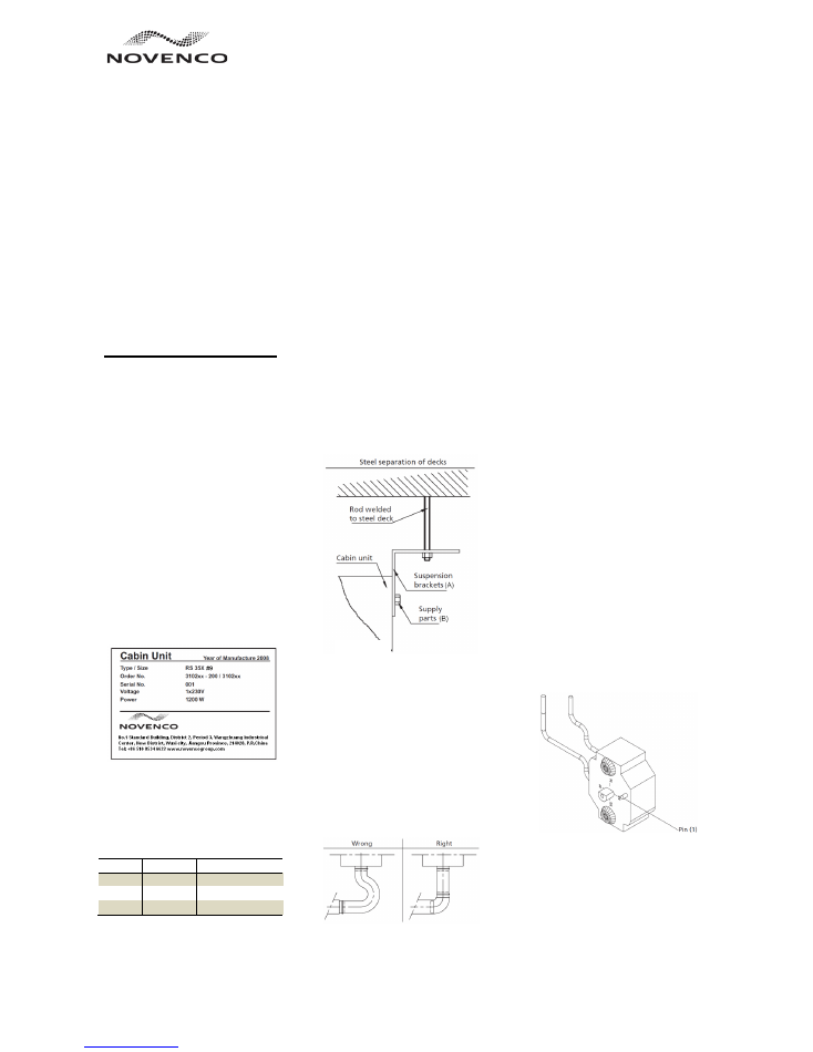
2.1 Marking
All cabin units are marked with
standard plates (figure 1). The plates
provide the name and address of
Novenco as well as the product type
and serial number, e.g. RS35X. The
serial number is unique for each unit.
In addition, the maximum power
consumption is also written on the
plates. The control boxes (CCU) are
also marked with plates showing type,
ID and serial number.
Figure 1
2.2 Weight
On request from the customer
Novenco can add the weights of the
cabin units to the marking of the
units.
Type
Weight [kg]
Dim. (HxWxL) [mm]
RS 35X
16.5
600x450x175
Diffuser
1.5
425x425x90
Total
18.0
——
Table 1
2.3 Transport
Cabin units from Novenco are packed
and delivered on pallets to allow
fork-lift transport.
3. Storage
The cabin units must be stored in a
dry place and at temperatures not
exceeding 45
o
C. Furthermore, it is
recommended to avoid long time
storage of the units in humid air
conditions (60% RH or more). This is
because of risk to the internal
electrical components, which are
unprotected against rust.
4. Installation
The cabin units are available for
ceiling suspension (figure 2). Units are
delivered with four suspension
brackets (A) incl. supply parts (B) for
fastening to the ceiling and sides of
the units.
It is important that the cabin units are
fastened to prevent sound nuisances,
caused by vibration.
5. Duct connections
The cabin units are designed for
connection to large duct systems on
e.g. ships. Connect the cabin units to
the systems using insulated flexible
hoses and clamping rings.
It is important that the flexible hose is
straightened out and that the length
does not exceed 300 mm (figure 3).
Figure 3
6. Electric connection
Power to the unit is supplied by
connecting 230V power cables to the
terminals L, N and PE as shown in the
wiring diagram. Refer also to the
electric diagram placed on the inside
of the lid of the terminal boxes.
Cables must be fastened by cable
glands before feeding the Cabin units.
For room thermostat, its cable must be
tied up and fixed. Refer to the wiring
diagrams for correct connection of
cables.
The required output from the heating
elements is selected on the three
toggle switch (400, 800 and 1200 W) in
the outflow connection of the cabin
units.
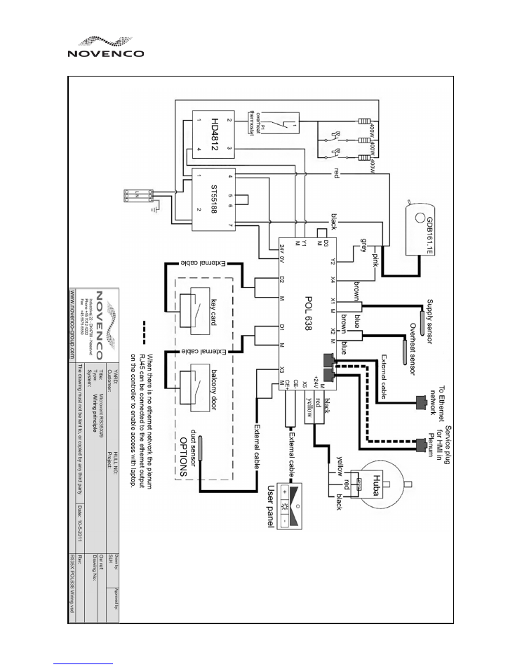
7. Wiring diagram
See figure 4 on page 3.
8. Thermostat
The cabin units are equipped with
both the temperature sensors and the
mechanical thermostats
for
overheating protection. The sensor
has a programmed reset function
while the mechanical thermostat has a
manual reset function.
The sensor will switch off the heating
and alarm will on, when the
temperature within the cabin unit
exceeds 70
o
C, and back on when the
heating elements have cooled
sufficiently off.
Figure 5
If the sensor fails, the mechanical
thermostat will switch off the heating,
when the temperature exceeds 110
o
C.
To re-activate the heating elements,
switch off the current to the cabin unit
in the fuse box. Remove the bottom
part of the diffuser by gently pulling
in the corners of the part. The manual
thermostat can then be accessed and
the small pin on the thermostat
Figure 2
MU 14633 1212
GB
2
/
3
No. 1 standard building, District 2, Period 3, Wangzhuang Industrical Center, New District,
Wuxi City, Jiangsu Province 214028, P.R.China
Tel: +86 510 8534 6622 Fax: +86 510 8534 6633
NOVENCO HI-PRES Air Handling Equipment (Wuxi) Co., Ltd
www.novenco-marine.com
pushed in to reset (figure 5). Remount
the diffuser by doing the above
procedure in reverse. The current can
be switched on when the cabin unit is
assembled.
Please note that resetting the
mechanical thermostat indicates that
the old temperature sensor must to be
replaced.
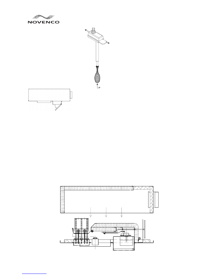
9. Regulation
To change the basic factory setting
(min. 40 m
3
/h at 1200 Pa), remove the
ceiling panel and insulation around
the cabin unit in case of a B-15 ceiling.
The motor box of the cabin unit
(figure 6) can then be accessed. Open
the box by pulling the lid downwards.
Figure 6
With the required supply pressure on
the cabin unit and fully open valve,
regulation of the cabin unit is done by
inserting a small screwdriver in the
square pipe that sticks out of the
motor (figure 7).
Figure 7
Push the screwdriver up into the pipe
and at the same time turn it round. By
doing so the regulator is shifted to the
side until the cabin unit delivers the
required air quality.
Close the lid after regulation of the air
quantity is complete. Remount the
insulation and the ceiling panel.
10. Parts included
Included with each cabin unit are four
suspension brackets complete with
screws and washers. A diffuser with
socket pipe is also included.
In addition, communication cables,
plugs and a user panel for the CCU
are included as well.
Further
documentations with
installation and commission details
are available on request from
Novenco.
11. Maintenance
Provided the cabin units are properly
installed, little or no maintenance is
required. It may, however, under
certain circumstances be desirable to
clean the inner parts of the cabin units.
In these cases it is recommended to
contact Novenco for further
information about the dismantling
and cleaning. Wrong treatment can
damage the insulation and other
parts.
The same applies if the cabin unit is
damaged and various parts have to be
replaced.
If cleaning or replacement of parts in
the cabin units is required, remove the
current and communication cables
and also the diffuser and ceiling panel.
After removal of the screws along the
edge of the bottom part, it is possible
to separate by lowering the bottom
part from the ceiling (figure 8, below).
Lower the part carefully. Be careful to
avoid damaging the insulation when
dismantling the cabin unit.
Clean the inner parts of the cabin
units with a damp cloth or a vacuum
cleaner. Assemble the cabin unit in
reverse order of the above.
Figure 8
GB
3
/
3
No. 1 standard building, District 2, Period 3, Wangzhuang Industrical Center, New District,
Wuxi City, Jiangsu Province 214028, P.R.China
Tel: +86 510 8534 6622 Fax: +86 510 8534 6633
NOVENCO HI-PRES Air Handling Equipment (Wuxi) Co., Ltd
www.novenco-marine.com
Figure 4