Full Text Searchable PDF User Manual
16
Cabling Audio Systems
1)
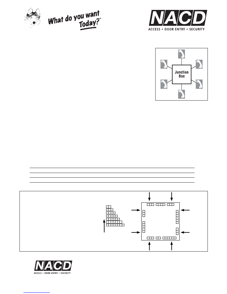
Cabling should be Star Configuration (Topology). ie. Each Handset cable should go back
to a junction box or central cabinet and NOT looped from one Handset to the next. This is
purely for maintenance reasons.
2)
It is recommended that 1mm diameter conductors are used from the power supply to the
(+) POSITIVE and (-) NEGATIVE of the speaker unit.
3)
It is recommended that 1mm (preferably 1.5mm) diameter conductors are used for the
lock circuit.
4)
Standard BT telephone cable is recommended (0.4mm per conductor) for reasons of
higher quality audio reproduction and because the pairs are twisted thereby providing a
powerful defence against interference.
5)
Standard alarm cable can also be used although there is a greater risk of interference.
Special care must be taken to ensure clean and neat terminations.
6)
All low voltage cabling must be run totally separated from high/mains voltage cables.
Please note that far better results are achieved using thicker conductors than combinations of
thinner conductors.
Power
Power the MIHP/6 Speaker using a 12V DC power source.
Amperage draw is dependent upon consumption characteristics of the locking used, the lengths of cable runs, the number of
handsets required to switch on simultaneously etc. As a general guide, allow 1 Amp per door. If unsure, please contact Noralsy.
Standby for Audio Systems
Simply add 12V battery to 12V DC power supply.
General Wire Diameter Guidlines – per conductor
Distance
Call/Speech/Release
Metres
CA, 2, 1, 9, 6
mm
50
0.4
100
0.8
200
1.0
300
1.6
For greater distances, please contact Noralsy for advice.
1 2 3
1
2
4
5
6
3
1
2
3
1
2
4
3
1
2
3
1
2
4
5
3
1
2
3
1
2
3
View Side-On
PCB Facing Up
View Side-On
PCB Facing Up
View Side-On
PCB Facing Up
View Side-On
PCB Facing Up
1 2
1 2 3
1 2
4
3
1 2
4 5
3
1 2
4 5 6
3
1 2
4 5 6 7
3
1 2
4 5 6 7 8
3
Direction of View
1 2
1 2
4 5 6
3
Any Noralsy
Control Unit
Door Controller
Speaker Unit
Access Pass Reader/Receiver
Keypad
Call Decoder
Module
Standardisation of
Terminal Numbering
Place Noralsy unit on a flat surface with
PCB facing skywards. View terminal blocks
from the outside looking in. Terminal No. 1
is always the first on the left of every
terminal block strip.
General Information
Our policy is one of continuous product improvement, we reserve the right to change specifications and prices without notice. All information is given in good faith. No responsibility can be accepted for errors, omissions or
incorrect assumptions. Picture reproduction of products are within the limitations of both colour and black and white printing and are intended as a guide only.
Star
Topology
N.A.C.D. LIMITED
UNIT 10, AVEBURY COURT, MARK ROAD, HEMEL HEMPSTEAD, HERTS HP2 7TA
TEL:
01442 211848
FAX:
01442 212776
EMAIL:
sales@nacd.co.uk
WEB:
http//:www.nacd.co.uk
NORALSY
™
MASTERING ACCESS CONTROL
™
™
12V
DC
Speak
er
I
NSTALLATION
I
NSTRUCTIONS
MIHP/6 S
PEAKER
Audio Entry
Single Entrance
Multiple Entrances with Automatic Switching
With
Fail Secure Locking
Fail Safe Locking
Automation
Keypad
Access Control
NORALSY
™
MASTERING ACCESS CONTROL
™
™

Contents
Page
General
3 -4
Single Entrance Audio System
5
2 Entrance Audio System
6
3 - 4 Entrance Audio System
7
5 - 6 Entrance Audio System
8
7 - 8 Entrance Audio System
9
Interfacing with a Keypad, Fail Secure Locking
10
Interfacing with a Keypad, Fail Safe Locking
10
“Volt Free” Automation
11
Interfacing with a Keypad, “Volt Free” Automation
11
Interfacing with Access Control, Fail Secure
12
Interfacing with Access Control, Fail Safe
12
Interfacing with Access Control, “Volt Free” Automation
12
Programming instructions for 30 Code/1 Relay Keypad
13
Programming instructions for 30 Code/3 Relay Keypad
14-15
Cabling Specifications
16
2
Audio Entry
Functional Systems
15
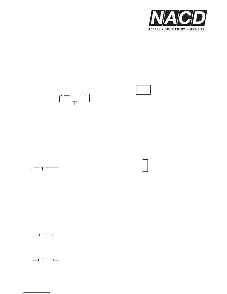
DELETING USER CODES
As all User Codes are stored in Slots, it is easy to delete a code from the keypad:
Enter the Master Code and wait for the beeps.
After a beep enter on the keypad:
or
To delete the User Code stored in Slot 01
To delete the User Code stored in Slot 17
A rapid series of beeps indicates that you have deleted successfully.
Now press B or # to escape from programming.
OVERWRITING / CHANGING USER CODES
You do not have to delete a User Code in order to change it. By programming a new User Code into a Slot that is currently in use,
you automatically erase the old User Code.
Enter the Master Code and wait for the beeps.
After a beep enter on the keypad:
The new User Code in Slot 01 is 700028. Whatever was in Slot 01 before has been erased.
Note: You change the Master Code in exactly the same way.
........to program Master Code 7767110 into Slot 30
Now press B or # to escape from programming.
LATCHING RELAY
The code stored in Slot 28 acts as the “ON” for Latching Relay no. 3.
The code stored in Slot 29 acts as the “OFF” for Latching Relay no. 3.
If you do not store a different code in Slot 29 to that stored in Slot 28, entering the code stored in Slot 28 will act first as
“ON” and then as “OFF”, then “ON” etc.
EMERGENCY CODE
The code stored in Slot 27 operates both Relay no. 1 and Relay no. 2 at the same time.
ANTI-TAMPER
An anti-tamper circuit (terminals 11 + 12 of J1) provides a normally closed contact, once the keypad is secured to the wall.
AUTOMATIC TIME-OUT - whenever programming accessed via Master Code
If you do not press B or # to escape from programming, the keypad will automatically revert to normal mode after 20 seconds.
30 7 7767110
Length of Code
Slot No.
Master Code
Itself
01 6 700028
Length of Code
Slot No.
User Code
17 A or
*
Slot No.
Delete Command
01 A or
*
Slot No.
Delete Command
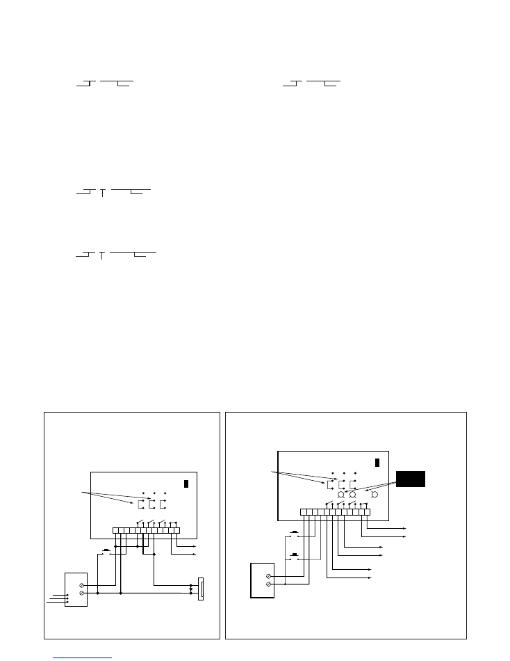
+12v
0v
J1
SW1 SW2 SW3
L
E
N
INV
NOR
+
–
EX1
EX1 = Exit Button
1 2
+ -
3 4 5 6 7 8 9 10 11 12
Jumper Setting
COMMON - NOR
For Fail Safe Locking
move jumper to:
COMMON - INV
(+ wire relays 1 & 2
in series)
SW5
Alarm Circuit (NC)
POWER SUPPLY
12V DC
12V DC
ELECTRIC
RELEASE
D1
+
–
Single Door Installation
26 user codes / relay nos 1 & 2 in parallel.
+12v
0v
J1
SW1
RV3
RV1
RV2
SW2 SW3
Alarm Circuit (NC)
SW5
INV
NOR
To Automation Control Equipment No.2
To Automation Control Equipment No.1
+
–
Jumper Setting
COMMON - NOR
EX1
EX1 activates Relay 1.
EX2 activates Relay 2.
(EX = Exit Button)
EX2
POWER SUPPLY
12V DC
1 2
+ -
3 4 5 6 7 8 9 10 11 12
Automation Control
13 user codes / relay no.1 , 13 user codes / relay no. 2.
Gate/Barrier Automation Control No. 1 = Main Gate (for example)
Gate/Barrier Automation Control No. 2 = Pedestrian Gate (for example)
Cut-out varistor RV1 or RV2 if its corresponding relay
is controlling an automation system.
Latching relay no. 3 (terminals 9-10) can be used to
hold open an automated gate/barrier etc.
In this instance only, cut-out varistor RV3.
CUT OUT
When power OFF
✄
ELEC/INST/K304
ELEC/INST/K301
Noralsy™ Keypad 30 codes / 3 Relays
Noralsy™ Keypad 30 codes / 3 Relays
14
N
ORALSY
™ K
EYPAD
30 C
ODES
/ 3 R
ELAYS
TOP POINTS TO REMEMBER
■
Master ( Engineer) Code is always stored in Slot 30.
■
User Codes are stored in Slots 01, 02, 03, 04..........26.
■
Relay no. 1 is controlled by the User Codes stored in Slots 01 - 13.
■
Relay no. 2 is controlled by the User Codes stored in Slots 14 - 26.
■
The code stored in Slot Number 27 activates Relay no. 1 & Relay no. 2 simultaneously.
■
The code stored in Slot Number 28 turns Latching Relay no. 3 “ON”.
■
The code stored in Slot Number 29 turns Latching Relay no. 3 “OFF”.
TIP - WHEN YOU ARE IN PROGRAMMING
Enter the numbers in quick succession after a beep. Do not wait more than 2-3 seconds in between entering numbers. If you have
correctly programmed, you will hear a rapid series of beeps.
SET-UP ON INSTALLATION
Wire up according to appropriate electrical schematic for your installation, then power up the keypad. Flick Programming Switch SW5
and wait for the keypad to start beeping every 3 seconds.
STEP 1
Decide Now......for how many seconds do you want the door to open:
After a beep enter
The 2no. digits shown as underlined set the door open time in seconds for relay no.1. The last 2no. digits set the door open time for
relay no.2. A rapid series of beeps indicates that you have programmed successfully.
You must set the relay/lock command time for relay no. 2 even if you are not using relay no. 2. If you have linked relays 1 &
2 together, you must set the same open times for both.
STEP 2
Now set the Master Code of your choice.
This is the code that allows you to access programming mode
without having to open up the keypad and flicking switch SW5.
The Master Code is always stored in Slot 30.
The Master Code can be any length of digits/characters/symbols -
minimum 3, maximum 8.
After a beep enter on the keypad:
if you want your Master Code to be 2901
A rapid series of beeps indicates that you have programmed successfully.
STEP 3
Turn off programming switch SW5.
STEP 4
PROGRAMMING/ADDING USER CODES
User codes can be any length of digits/characters/symbols - minimum 3, maximum 8.
User codes are stored in Slots 01-26. Example: 01, 02, 03… 26.
Enter the Master Code you set in STEP 2 and wait for the beeps.
After a beep enter on the keypad:
..............to program User Code 494 into Slot 01
A rapid series of beeps indicates that you have programmed successfully.
.............to program User Code 5519 into Slot 02
A rapid series of beeps indicates that you have programmed successfully.
Now press B or # to escape from programming.
02 4 5519
Length of Code
Slot No.
User Code
01 3 494
Length of Code
Slot No.
User Code
30 4 2901
Length of Code
Slot No.
Master Code
Itself
00 05 05
Relay No. 1
Set Timer
Command
Relay No. 2
05
Example
Seconds
This is an example only.
SET THE MASTER CODE OF
YOUR CHOICE
NOTE:
Relays can be programmed
between 01 – 99 seconds.
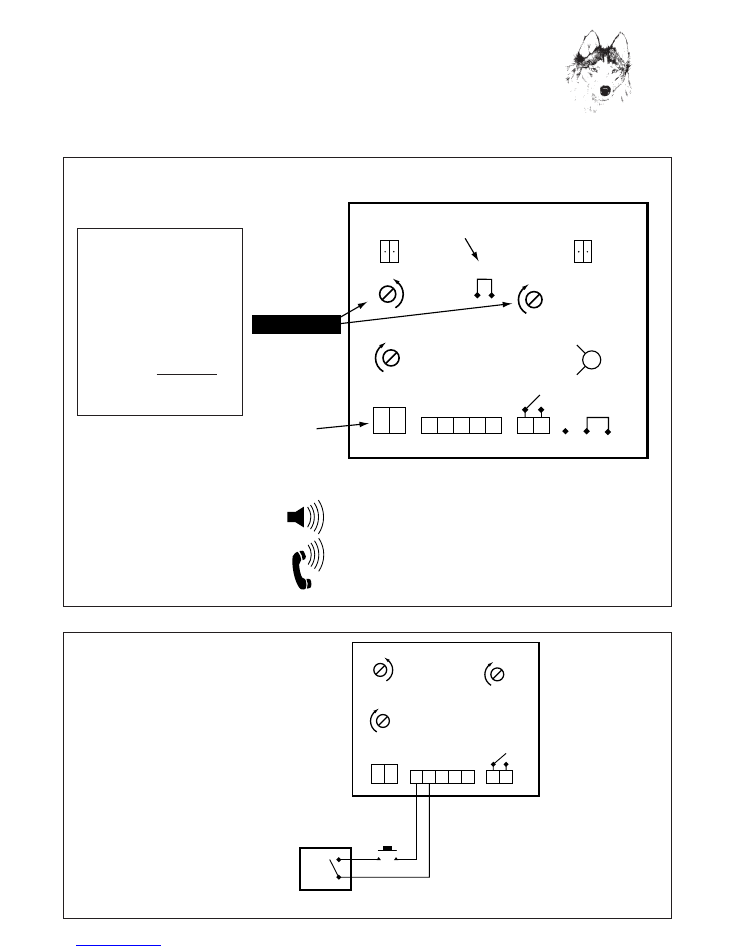
J1
J2
J3
Speaker
MIHP/6
1 2
1 2
1 2
+ –
3 4 5
TR
TIME CLOCK
TR = Trades-Button
(Normally open contact)
P1
P3
P2
–
+
–
+
–
+
ELEC/INST/300B
Adding a Trades-Button
controlled via a Time Clock
3
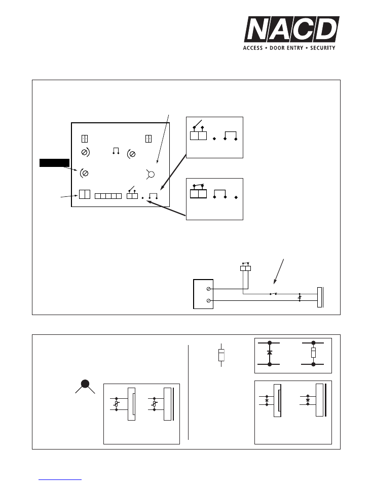
Noralsy Speaker MIHP/6
NORALSY
™
MASTERING ACCESS CONTROL
™
™
P1
J1
J5
J4
J8
J2
J3
J9
P3
P2
RV1
1 2
1 2
+ –
1 2 3 4 5
INV
NOR
Removing jumper reduces
gain of microphone
12V DC
Power Input
Speaker MIHP/6
–
+
–
+
–
+
Potentiometers
P2
= For adjusting speech/sound level
down to the external panel.
P3
= For adjusting speech/sound level
up to the handset(s).
Speech & Audio Settings
ELEC/INST/300
1. Turn P3 clockwise to
zero = No speech from
panel to handset.
2. Adjust P2 clockwise so
that speech level at
panel is at an acceptable
level. Do not increase
beyond this point.
3. Adjust P3 fractionally
anti-clockwise to “turn
on” microphone.
J4
= Prewired/connected to speaker (if not
connected simply plug in).
J5
= Prewired/connected to microphone (if not
connected simply plug in).
J8
= On short runs especially, removing the jumper
reduces the gain of the microphone.
4
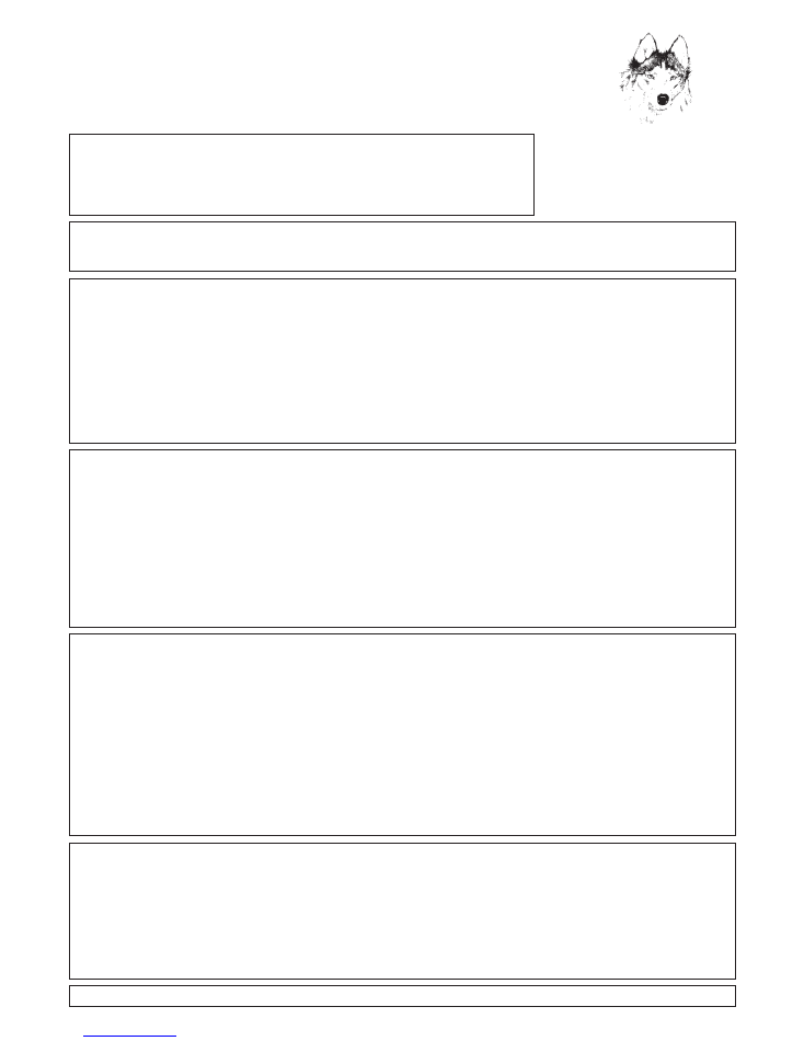
Noralsy Speaker MIHP/6
Common - NOR
= Relay closes (makes circuit)
when door release button on
handset or internal exit button is
pressed. This setting is used
when operating a fail secure
(locked) - power to unlock
electric release.
J1
J5
J4
J8
J2
J3
J9
RV1
1 2
1 2
+ –
1 2 3 4 5
INV
NOR
Potentiometer
12V DC
Power Input
If controlling an
automation system,
see note.
Speaker MIHP/6
P1
P3
P2
–
+
–
+
–
+
P1
= For adjusting relay J3 operating time (output
time) to lock or automation equipment.
RV1 = Cut out only if relay J3 is connected directly to
an automation system.
Common - INV
= Relay opens (breaks) circuit
when door release button on
handset or internal exit button is
pressed. This setting is used
when operating a fail safe (open)
- power to lock electro-magnet
or electric release.
EMEX
POWER SUPPLY
+12v
0v
Magnet
or Fail Safe
Release
1 2
J3
Varistor
If your fail safe locking requires an Emergency Break
Glass exit device ref. EMEX (normally closed contact) in
order to comply with relevant fire and safety regulations,
please fit as shown.
J3
1 2
J9
INV
NOR
J3
J9
1 2
INV
NOR
Fail Secure (N.O.)
Fail Safe (N.C.)
Jumper Settings J9 for Relay J3
ELEC/INST/300A
Protection Varistor or Diode
The use of a varistor or diode protects electrical equipment from
transient voltage spikes.
+
–
+
–
Diode
Varistor
DC release
Fail Secure or
Fail Safe
K = Cathode +
A = Anode –
Electro
Magnet
AC or DC
release
Electro
Magnet
Fit the diode ref. IN4001
close to the DC release
or electro-magnet.
Respect polarity of the
diode. Incorrect fitting of
a diode will cause a
short circuit.
Fit the varistor close to the
AC or DC release or the
DC magnet.
Varistor is polarity
insensitive.
+
–
K
A
–
K
A
+
+
or
D
D
D
D
V
V
or
–
Noralsy™ Keypad
30 Codes / 1 Relay
SET-UP ON INSTALLATION
Wire up according to appropriate electrical schematic for your installation, then power up the unit.
Flick the programming switch SW1 and wait for unit to start beeping every 3 seconds.
SET THE MASTER CODE. IT MUST BE STORED IN SLOT 06.
Example:
You want the following MASTER CODE: 74AB6
After a beep enter on the keypad:
06
5
74AB6
Master Code Slot Number
Length of Code
Master Code Itself
If you have correctly entered the Master Code you will hear 2no. series of rapid beeps.
Turn off Programming Switch SW1. You can now effect all programming simply by entering the Master Code and waiting for the
programming beeps.
TOP POINTS TO REMEMBER
1.
Up to 29 user entry codes available at any one time.
2.
Codes are stored in slots numbered 01, 02, ....05 and 07, 08......30.
3.
Master Code = Programming code and must be stored in Slot 06.
4.
Each code can be any mix of digits/letters from 3 to 8 in length.
TIP - WHEN YOU ARE PROGRAMMING
Enter the numbers in quick succession after a beep. Do not wait more than 2-3 seconds in between entering numbers as this will
confuse the keypad. If you have correctly programmed, you will hear a rapid series of beeps.
SETTING USER DOOR ENTRY CODES
Enter the Master Code onto the keypad and wait for the beeps.
Example: you want the following codes:
A94
= 3 digits
564B52
= 6 digits
After a beep enter on the keypad:
01
3
A94
Slot Number
Length of Code
Code Itself
02
6
564B52
Slot Number
Length of Code
Code Itself
NOTE CAREFULLY:
No codes into slot no. 06 as this is for the Master Code !
(Unless, of course, you want to change the Master Code).
Press B to escape from programming.
DELETING USER DOOR ENTRY CODES
As all door entry codes are stored in slot numbers 01 - 05 and 07 - 30, it is easy to delete a code from the system.
NOTE CAREFULLY
- Do not delete slot no. 06 unless you are going to input a new Master Code whilst still in programming mode !
Example - Your codes are:
A94
for Mr Smith
stored in Slot 01
564B52
for Staff use
stored in Slot 02
To delete Mr Smith’s code - A94 - from the system simply:
Enter the Master Code onto the keypad and wait for the beeps.
After a beep enter on the keypad:
01
A
Slot Number
Delete Command
Press B to escape from programming.
Note 1.
You do not have to know the actual code itself which needs to be deleted, only the slot in which it is stored.
Note 2.
Capacity is never reduced as a result of deleting codes. You can always add or change codes.
SETTING LOCK OPEN TIME
Enter the Master Code onto the keypad and wait for the beeps.
Lock open time can be set at
0.2
seconds or
01 - 99
seconds.
After a beep enter:
00 00
for 0.2 seconds (automation control)
00 05
for 05 seconds
00 10
for 10 seconds
00 19
for 19 seconds etc
Press B to escape from programming.
If you do not press B to escape from programming, the keypad automatically reverts to normal mode after 20 seconds.
13
NORALSY
™
MASTERING ACCESS CONTROL
™
™
12
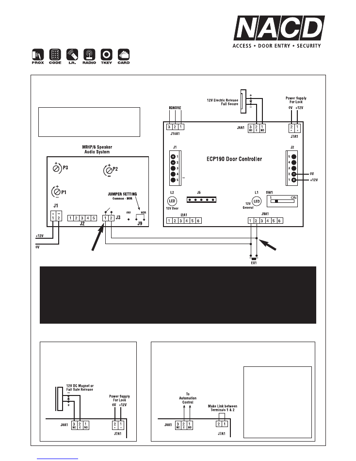
Audio System Interface
with Stand-Alone Access Control
Fail Secure (Locked) – Power to Unlock
ELEC/INST/309
Fail Safe (Open) –
Power to Lock
ELEC/INST/310
Automation Control / Volt Free
ELEC/INST/311
Set output time on speaker MIHP/6 (via
potentiometer P1) to slightly above
minimum. Program required lock
release time on ECP Door Controller.
Set output time on
speaker MIHP/6 (via
potentiometer P1) to
slightly above minimum
and program output time
on ECP Door Controller
to 01 seconds.
Program output time
accordingly if more time
is required to trigger
automation system.
Relay J3 used as a N.O. Volt Free change-over relay
to trigger relay (lock) output of ECP Door Controller
(Door Controller/Control Unit from 3rd party) via
standard internal exit button terminal connections.
Relay J3
EX1 = Internal Exit Button
Exit Button Input
Terminals
ECP Door Controller
ECP Door Controller
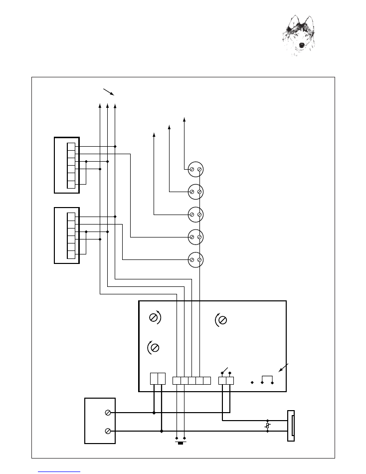
5
Noralsy Speaker MIHP/6
with 1131 Audio Handsets
ELEC/INST/301
(-) Negative Common
Speech Down (SD) + RS
Speech Up (SU)
(-) Negative Common
Speech Down (SD) + RS
Speech Up (SU)
Call line handset 1
Call line handset 2
Call line handset 3
Call line handset 4
Call line handset 5
POWER SUPPLY
12V DC
+12v
0v
J1
J2
J3
J9
Call Button 5
Call Button 4
Call Button 3
Call Button 2
Call Button 1
Speaker
MIHP/6
Handset 2
Handset 1
Handset 3
Handset 4
Handset 5
To Handset 3, 4, 5 etc.
ie. Terminal 1 of Handset
ie. Terminal CA of Handset
6 2 1
CA
CA
CA
12V
Electric
Release
Varistor
EX1
1 2
1 2
1 2
+ –
3 4 5
EX1 = Door release button
sited internally.
(Normally open contact)
RS = Release Signal
INV
NOR
JUMPER SETTING
(For fail safe locking
move jumper to
Common-INV)
6
10
9
2
CA
1
6
10
9
2
CA
1
P1
P3
P2
–
+
–
+
–
+
NORALSY
™
MASTERING ACCESS CONTROL
™
™
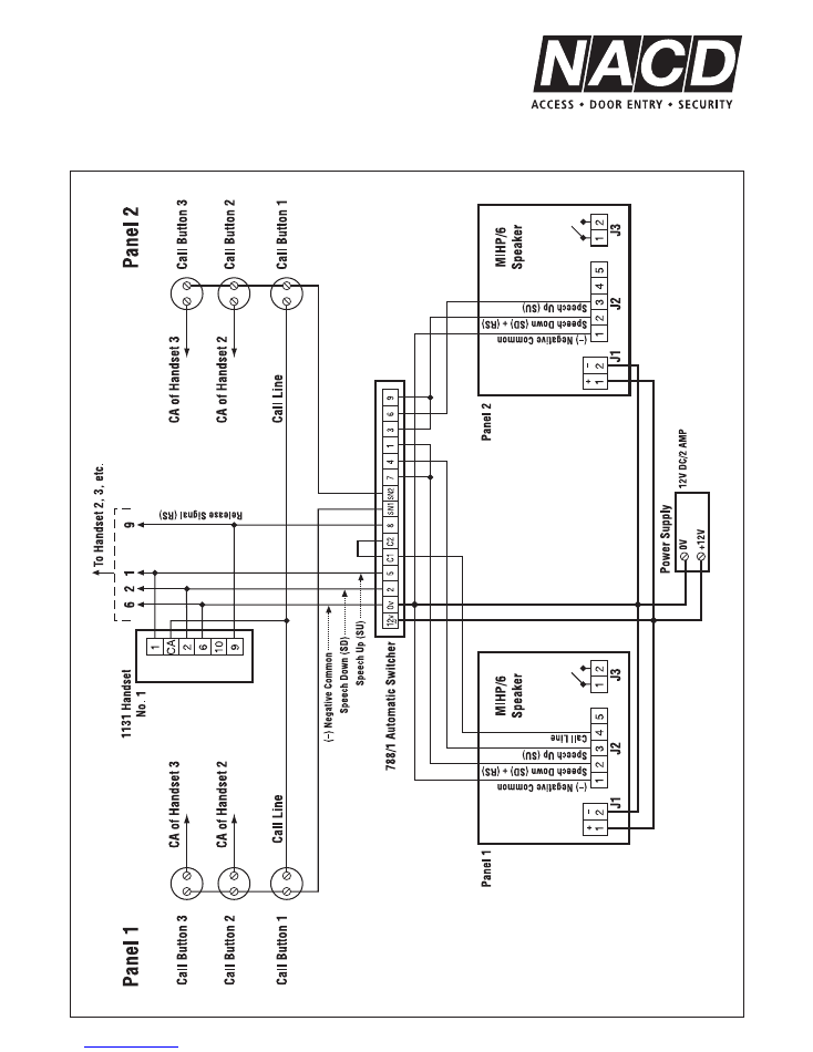
6
Noralsy Speaker MIHP/6
Audio Entry 2 Entrances
Automatic Switching
ELEC/INST/303
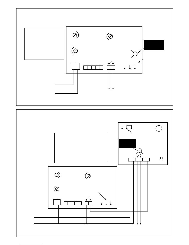
11
+12VDC
0V
J1
J2
J3
J9
Speaker
MIHP/6
1 2
1 2
1 2
+ –
3 4 5
INV
NOR
JUMPER SETTING
Common-NOR
To
Automation Control
RV1
CUT OUT
When power off
✄
Set output time on speaker
MIHP/6 (via Potentiometer
P1) to slightly above
minimum.
Adjust accordingly if more time
is required to trigger automation
system.
P1
P3
P2
–
+
–
+
–
+
Automation Control / Volt Free
MIHP/6 Speaker Audio System
J1
J2
J3
Speaker
MIHP/6
KEYPAD MODULE
30 Codes / 1 Relay
1 2
+ -
3 4 5 6
J1
SW1
KEYPAD
INV
NOR
INV
NOR
BUZZER
JUMPER SETTING
Common – NOR
1 2
1 2
1 2
+ –
3 4 5
JUMPER SETTING
Common-NOR
+12VDC
0V
To
Automation Control
Set output time on speaker MIHP/6
(via potentiometer P1) to slightly
above minimum and program output
time on keypad to 0.2 seconds.
Program keypad output time accordingly if more
time is required to trigger automation system.
RV1
CUT OUT
When power off
✄
P1
P3
P2
–
+
–
+
–
+
Automation Control / Volt Free
MIHP/6 Speaker Audio System + Keypad
ELEC/INST/307
ELEC/INST/308
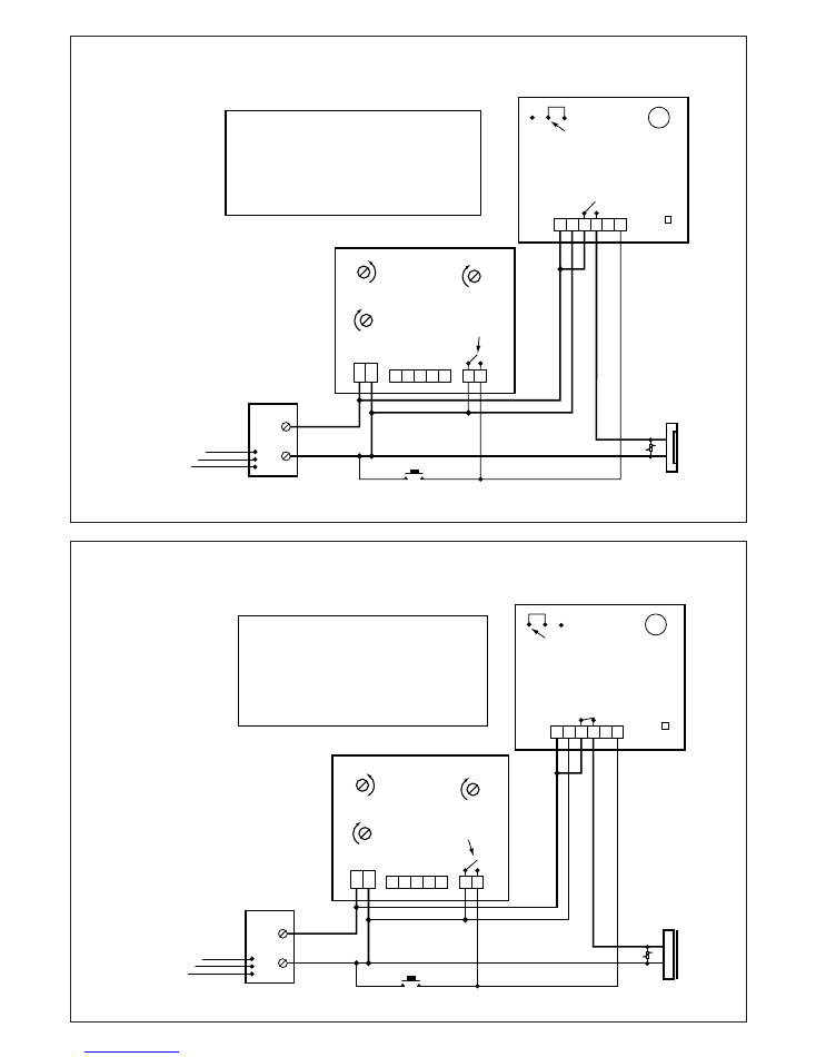
10
POWER SUPPLY
12V DC
KEYPAD MODULE
30 Codes / 1 Relay
+12v
0v
L
E
N
J1
J2
J3
12V
Electric
Release
Varistor
EX1
Speaker
MIHP/6
1 2
+ -
3 4 5 6
J1
SW1
KEYPAD
INV
NOR
BUZZER
JUMPER SETTING
Common – NOR
1 2
1 2
1 2
+ –
3 4 5
EX1 = Door release button
sited internally.
(Normally open contact)
Fail Secure (Locked) - Power to Unlock
Fail Secure (Locked) -
Power to Unlock
Set lock release time on speaker
MIHP/6 (via potentiometer P1) to
slightly above minimum. Program
required lock release time on keypad.
JUMPER SETTING J9
Common-NOR
P1
P3
P2
–
+
–
+
–
+
Fail Secure Locking
MIHP/6 Speaker Audio System + Keypad
ELEC/INST/305
ELEC/INST/306
POWER SUPPLY
12V DC/1AMP
KEYPAD MODULE
30 Codes / 1 Relay
+12v
0v
L
E
N
J1
J2
J3
12V DC
Magnet
or
Fail Safe Release
Varistor
EX1
Speaker
MIHP/6
1 2
+ -
3 4 5 6
J1
SW1
KEYPAD
INV
NOR
BUZZER
JUMPER SETTING
Common – INV
JUMPER SETTING J9
Common-NOR
1 2
1 2
1 2
+ –
3 4 5
EX1 = Door release button
sited internally.
(Normally open contact)
Fail Safe (Open) - Power to Lock
Set lock release time on speaker
MIHP/6 (via potentiometer P1) to
slightly above minimum. Program
required lock release time on keypad.
Fail Safe (Open) -
Power to Lock
P1
P3
P2
–
+
–
+
–
+
Fail Safe Locking
MIHP/6 Speaker Audio System + Keypad
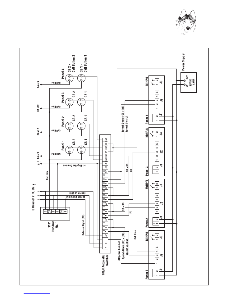
7
Noralsy Speaker MIHP/6
Audio Entry 3 or 4 Entrances
Automatic Switching
ELEC/INST/304
NORALSY
™
MASTERING ACCESS CONTROL
™
™
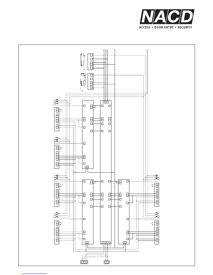
3
2
1
J3
J2
J1
3
4
1
7
SN1
9
10
6
2
1
CA
9
10
6
2
1
CA
5
2
11
8
C1
C2
5
2
11
8
C1
C2
1
I
2
I
_ I
AP
I
SN1
AP
2
1
1
III
2
III
_
III
AP
III
SN3
1
II
2
II
_
II
AP
II
SN2
1
IV
2
IV
_
IV
AP
IV
SN4
2
1
4
5
2
1
2–
1+
3
2
1
MIHP/6
Panel 1
Call Buttons
SU
SD + RS
3
2
1
J3
J2
J1
3
2
1
4
5
2
1
2–
1+
3
2
1
MIHP/6
Panel 2
Call Buttons
SU
SD + RS
3
2
1
J3
J2
J1
3
2
1
4
5
2
1
2–
1+
3
2
1
MIHP/6
Panel 3
Call Buttons
SU
SD + RS
3
2
1
J3
J2
J1
3
2
1
4
5
2
1
2–
1+
3
2
1
J3
J2
J1
3
2
1
4
5
2
1
2–
1+
MIHP/6
Panel 6
3
2
1
Call Buttons
J3
J2
J1
3
2
1
4
5
2
1
2–
1+
MIHP/6
Panel 5
3
2
1
Call Buttons
MIHP/6
Panel 4
Call Buttons
SU
SD + RS
SU
SD + RS
SU
SD + RS
6
3
9
~12 ~0
SN2
4
1
7
SN1
5
2
11
8
C1
C2
6
3
9
~12
~0
SN2
4
1
7
SN1
6
3
9
~12
DIP
E
+
+12 ~0
~0
C1
C2 ~12 ~0
–
SN2
788/8
788/1
788/1
788/1
SU
SD
RS
SU
SD
RS
CALL LINE 2
CALL LINE 1
CALL LINE 3
CALL LINE 3
CALL LINE 2
CALL LINE1
(–) Negative
Common
(–) Negative Common
1131 Handset No. 2
1131 Handset No. 1
S500 TNG
PSU 12VDC
6 AMP
To Handset 3, 4, etc.
8
Noralsy Speaker MIHP/6
Audio Entry 5 or 6 Entrances
Automatic Switching
ELEC/INST/304X
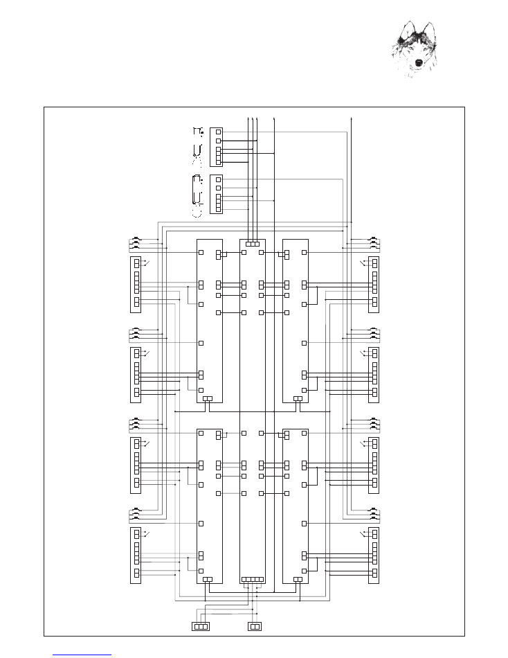
3
2
1
J3
J2
J1
3
4
1
7
SN1
9
10
6
2
1
CA
9
10
6
2
1
CA
5
2
11
8
C1
C2
5
2
11
8
C1
C2
1
I
2
I
_ I
AP
I
SN1
AP
2
1
1
III
2
III
_
III
AP
III
SN3
1
II
2
II
_
II
AP
II
SN2
1
IV
2
IV
_
IV
AP
IV
SN4
2
1
4
5
2
1
2–
1+
3
2
1
MIHP/6
Panel 1
J3
J2
J1
3
2
1
4
5
2
1
2–
1+
MIHP/6
Panel 8
Call Buttons
SU
SD + RS
SU
SD
RS
SU
CALL LINE 2
CALL LINE 1
CALL LINE 3
(–) Negative
Common
SD
RS
3
2
1
J3
J2
J1
3
2
1
4
5
2
1
2–
1+
3
2
1
MIHP/6
Panel 2
Call Buttons
SU
SD + RS
3
2
1
J3
J2
J1
3
2
1
4
5
2
1
2–
1+
3
2
1
MIHP/6
Panel 3
Call Buttons
SU
SD + RS
3
2
1
J3
J2
J1
3
2
1
4
5
2
1
2–
1+
3
2
1
3
2
1
Call Buttons
J3
J2
J1
3
2
1
4
5
2
1
2–
1+
MIHP/6
Panel 7
3
2
1
Call Buttons
J3
J2
J1
3
2
1
4
5
2
1
2–
1+
MIHP/6
Panel 6
3
2
1
Call Buttons
J3
J2
J1
3
2
1
4
5
2
1
2–
1+
MIHP/6
Panel 5
3
2
1
Call Buttons
MIHP/6
Panel 4
Call Buttons
SU
SD + RS
SU
SD + RS
SU
SD + RS
SU
SD + RS
SU
SD + RS
6
3
9
~12 ~0
SN2
4
1
7
SN1
5
2
11
8
C1
C2
6
3
9
SN2
4
1
7
SN1
5
2
11
8
C1
C2
6
3
9
~12
~0
SN2
4
1
7
SN1
6
3
9
~12
DIP
E
+
+12 ~0
~0
C1
C2 ~12 ~0
–
SN2
788/8
788/1
788/1
788/1
788/1
1131 Handset No. 2
To Handset 3, 4, etc.
1131 Handset No. 1
~0 ~12
S500 TNG
PSU 12VDC
8 AMP
9
Noralsy Speaker MIHP/6
Audio Entry 7 or 8 Entrances
Automatic Switching
ELEC/INST/304Y
NORALSY
™
MASTERING ACCESS CONTROL
™
™