Full Text Searchable PDF User Manual

PMFY-1
2012 PMFY-P-NBMU-ER5 (October 2012)
© 2012 Mitsubishi Electric US, Inc.
PMFY-P-NBMU-ER5
1. SPECIFICATIONS ................................................................................................................................................. PMFY-3
2. EXTERNAL DIMENSIONS .................................................................................................................................... PMFY-4
3. CENTER OF GRAvITY ......................................................................................................................................... PMFY-5
4. ELECTRICAL WIRING DIAGRAMS ...................................................................................................................... PMFY-6
5. SOUND PRESSURE LEvELS .............................................................................................................................. PMFY-7
5-1. Sound Pressure Levels ............................................................................................................................... PMFY-7
5-2. NC Curves ................................................................................................................................................... PMFY-7
6. TEMPERATURE/AIRFLOW DISTRIBUTIONS ..................................................................................................... PMFY-8
6-1. Temperature Distributions ........................................................................................................................... PMFY-8
6-2. Airflow Distributions ..................................................................................................................................... PMFY-8
7. OPTIONAL PARTS ................................................................................................................................................ PMFY-9
7-1. External Heater Adapter CN24RELAY-KIT-CM3 ......................................................................................... PMFY-9
CEiliNg-RECEssEd CassEttE (ONE-waY aiRFlOw)
PMFY-2
2012 PMFY-P-NBMU-ER5 (October 2012)
© 2012 Mitsubishi Electric US, Inc.
IU - D - 2
Cassette ceiling (1-way flow type)
DATA U3
PMFY-P-NBMU-E
I.Cassette ceiling (1-way flow type)
PMFY-P-NBMU-E
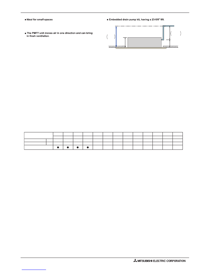
Compact and lightweight-perfect for limited ceiling space applications.
The PMFY models are one-way ceiling-recessed cassette units
perfect for shallow ceiling spaces.
It is designed especially for use in areas like hotel rooms that
cannot support ductwork or lack sufficient space to allow
for wall-mounted units.
Unit body size has been standardized for all models at 33-5/8" for
easier installation. This profile is the smallest of all CITY MULTI™
ceiling models with a depth of only 9-1/16"-ideal for tight location.
7-25/32”
Drain pipe
Ceiling
PMFY-NBMU-ER5
max.
23-5/8”
9-1/16”
max.
15-13/16”
PMFY-P-NBMU-E
PMFY-P-NBMU-ER5
3.2HP
8.0HP
4.0HP
5.0HP
P08
P12
P15
P18
P30
P36
P48
P06
P24
P27
P54
P72
10.0HP
P96
0.8HP
1.0HP
1.3HP
1.6HP
2.0HP
2.5HP
2.8HP
5.6HP
Cassette ceiling
48,000
6,700
Nominal cooling cap.*1
Nominal heating cap.*2
6,000
8,000
12,000
15,000
18,000
24,000
27,000
30,000
36,000
54,000
72,000
96,000
60,000
80,000 108,000
27,000
30,000
34,000
40,000
54,000
9,000
13,500
17,000
20,000
Btu/h
Btu/h
* Nominal conditions *1, *2 are referred to in the Specification sheet.
unit: in.
CEiliNg-RECEssEd CassEttE (ONE-waY aiRFlOw)
PMFY-3
2012 PMFY-P-NBMU-ER5 (October 2012)
© 2012 Mitsubishi Electric US, Inc.
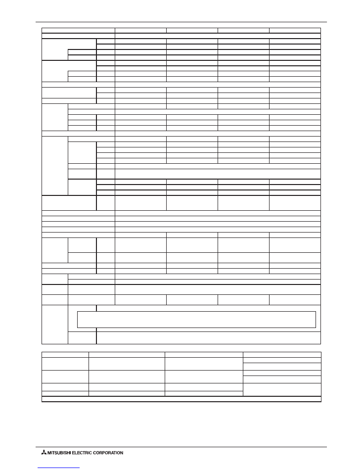
Model
PMFY-P06NBMU-ER5
PMFY-P08NBMU-ER5
PMFY-P12NBMU-ER5
PMFY-P15NBMU-ER5
Power source
1-phase 208-230 v 60Hz
Cooling capacity *1
(Nominal)
Btu/h
6,000
8,000
12,000
15,000
kW
1.8
2.3
3.5
4.4
Power input
kW
0.04
0.04
0.04
0.05
Current input
A
0.20
0.20
0.21
0.26
Heating capacity *2
(Nominal)
Btu/h
6,700
9,000
13,500
17,000
kW
2.0
2.6
4.0
5.0
Power input
kW
0.04
0.04
0.04
0.05
Current input
A
0.20
0.20
0.21
0.26
External finish
-
External dimension H x W x D
in.
9-1/16 x 31-31/32 x 15-9/16 9-1/16 x 31-31/32 x 15-9/16 9-1/16 x 31-31/32 x 15-9/16 9-1/16 x 31-31/32 x 15-9/16
mm
230 x 812 x 395
230 x 812 x 395
230 x 812 x 395
230 x 812 x 395
Net weight
lbs (kg)
31 (14)
31 (14)
31 (14)
31 (14)
Decoration
panel
Model
PMP-16BMUW
PMP-16BMUW
PMP-16BMUW
PMP-16BMUW
External finish
6.4Y 8.9/0.4
Dimension
in.
1-3/16 x 39-3/8 x 18-17/32
1-3/16 x 39-3/8 x 18-17/32
1-3/16 x 39-3/8 x 18-17/32
1-3/16 x 39-3/8 x 18-17/32
H x W x D
mm
30 x 1,000 x 470
30 x 1,000 x 470
30 x 1,000 x 470
30 x 1,000 x 470
Net Weight
lbs (kg)
7(3)
7(3)
7(3)
7(3)
Heat exchanger
Cross fin
FAN
Type x Quantity
Line flow fan x 1
Line flow fan x 1
Line flow fan x 1
Line flow fan x 1
External
static pressure
in.WG
0.000 (208v)
0.000 (208v)
0.000 (208v)
0.000 (208v)
Pa
0
0
0
0
in.WG
0.000 (230v)
0.000 (230v)
0.000 (230v)
0.000 (230v)
Pa
0
0
0
0
Motor type
DC Brushless
Driving
mechanism
Direct-driven
Airflow rate
(Low-Mid1-
Mid2-High)
CFM
230-254-283-307
258-283-304-328
258-283-304-328
272-307-343-378
m3 / min
6.5-7.2-8.0-8.7
7.3-8.0-8.6-9.3
7.3-8.0-8.6-9.3
7.7-8.7-9.7-10.7
L / s
108-120-133-145
122-133-143-155
122-133-143-155
128-145-162-178
Sound pressure level
(Low-Mid1-Mid2-High)
(measured in anechoic room)
dB <A>
27-30-33-35 (208-230v)
32-34-36-37 (208-230v)
32-34-36-37 (208-230v)
33-35-37-39 (208-230v)
Insulation material
PS foam, Polyethylene foam
Air filter
PP honeycomb
Protection device
Fuse
Refrigerant control device
LEv
Connectable outdoor unit
R410A CITY MULTI
R410A CITY MULTI
R410A,R22 CITY MULTI
R410A,R22 CITY MULTI
Diameter of
refrigerant
pipe (O.D.)
Liquid (R410A)
(R22)
in. (mm)
1/4 (6.35) Flare
-
1/4 (6.35) Flare
-
1/4 (6.35) Flare
1/4 (6.35) Flare
1/4 (6.35) Flare
1/4 (6.35) Flare
Gas (R410A)
(R22)
in. (mm)
1/2 (12.7) Flare
-
1/2 (12.7) Flare
-
1/2 (12.7) Flare
1/2 (12.7) Flare
1/2 (12.7) Flare
1/2 (12.7) Flare
Field drain pipe size
in. (mm)
O.D. 1 (26)
O.D. 1 (26)
O.D. 1 (26)
O.D. 1 (26)
Drain lift mechanism
in. (mm)
23-5/8 (600)
23-5/8 (600)
23-5/8 (600)
23-5/8 (600)
Drawing
External
BH01C848
Wiring
BH79C630
Standard
attachment
Document
Accessory
Installation Manual,Installation Book
Optional
parts
External heater adapter
CN24RELAY-KIT-CM3
CN24RELAY-KIT-CM3
CN24RELAY-KIT-CM3
CN24RELAY-KIT-CM3
Remark
Installation
Details on foundation work, duct work, insulation work, electrical wiring, power source switch, and other items shall be referred to
the Installation Manual.
Ventilation Air: Providing sufficient ventilation air is an important part of every building design.
ASHRAE standard 62 provides the minimum ventilation air requirements. Also check local codes.
1. sPECiFiCatiONs
Note:
*1 Nominal cooling conditions
*2 Nominal heating conditions
Unit converter
Indoor:
80degF D.B. / 67degF W.B.
(26.7degC D.B. / 19.4degC W.B.)
70degF D.B. (21.1degC D.B.)
kcal/h = kW x 860
BTU/h = kW x 3,412
Outdoor:
95degF D.B. (35degC D.B.)
47degF D.B. / 43degF W.B.
(8.3degC D.B. / 6.1degC W.B.)
cfm = m3/min x 35.31
lbs = kg / 0.4536
Pipe length:
25 ft. (7.6 m)
25 ft. (7.6 m)
*Above specification data is
subject to rounding variation.
Level difference:
0 ft. (0 m)
0 ft. (0 m)
*Due to continuing improvement, above specification may be subject to change without notice.
PMFY-4
2012 PMFY-P-NBMU-ER5 (October 2012)
© 2012 Mitsubishi Electric US, Inc.
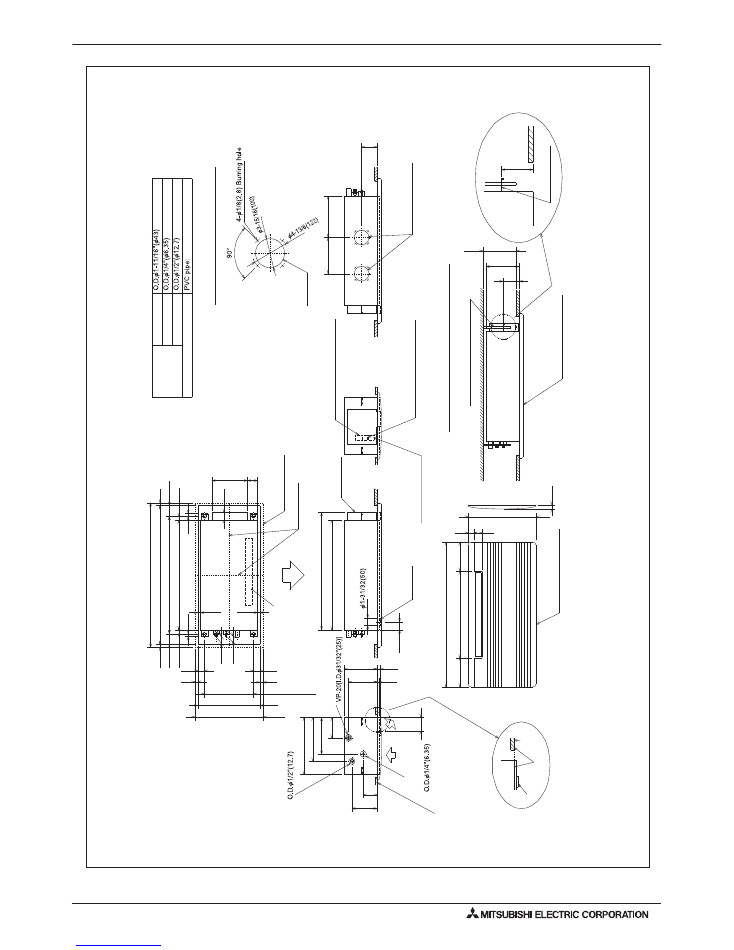
Detail drawing of fresh air intake hole
Knock out
Fresh air intake hole
4-5/16 (110
)
9-1/16(230)
9-1/2
(235) or more
4-5/16
(110
)
suspension bolt(M10 or W 3/8)
Panel(grille
):PMP-40BM
Installation space required around indoor unit
mounting plate
6-15/16(176)
Panel(grille
):PMP-40BM
Lower view
2-3/8(60)
1-9/16(40)
7-7/8(200)
23-5/8(600)
7-7/8(200)
To
p
Air outlet(lower)
1-13/18(46)
1-
11/16(43
)
13/16(20)
13/16(20)
2-1/16(53)
2-11/16(69
)
9-3/8(247)
1-3/16(30)
Right side
outer line of grille
center of unit
29-7/8(759)
1-1/32(26)
31-15/18(8
11
) suspension bolt pitch
2-15/18(74.5)
37-13-16(960)
ceilin
g opening
13/16(20)
1-1/32(26)
2-15/18(74.5)
13/16(20)
39-3/8(1000)
outer side of grille
11/16(17.5
)11/16(17.5
)
1-25/32(45)
13-3/8(340) suspension bolt pitc
h
1-25/32(45)
16-15/16(430)
ceiling opening
18-1/2(470)
outer side of grille
13/16(20)
13/16(20)
Terminal block for power suppl
y
Terminal block for transmissio
n
31-15/16(812)
3-3/8(96)
Left side
Front
drain pan
electrical box
Integral lift pump outlet pipe:
Refrigerant pipe(gas)
Refrigerant pipe(liquid)
ceilin
g panel
drain pan
ceilin
g
panel
Drainage piping
Gas pipe
I.D. 1-1/32" (26)
Liquid pipe
Pipe cover
Refrigerant piping
39-3/8(1000) outer side of grille
18-1/2(470)
outer side of grille
2-3/16(56)
9-1/16(230)
3-3/8(96)
13/16(20)
13/32(10)
11-7/8(302
)
10(254)
7-13/16(198)
5-9/16(141)
29-7/8(759)
15-9/16(395)
4-1/4
(108)
9-13/16(250)
11-3/8(288.5
)
same line
Terminal block for
remote-controller
PMFY-P06,08,12,15NBMU-ER5
Drw. : IU-BH01C848
Unit : in(mm)
2. ExtERNal diMENsiONs
PMFY-5
2012 PMFY-P-NBMU-ER5 (October 2012)
© 2012 Mitsubishi Electric US, Inc.
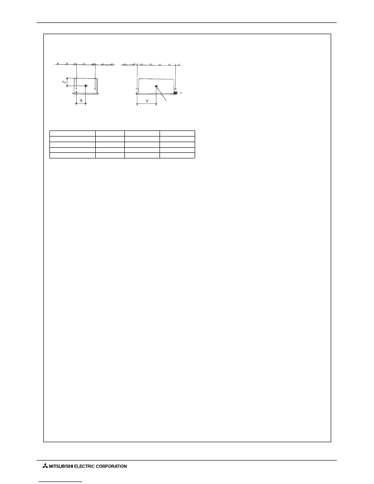
3. CENtER OF gRavitY
PMFY-P06,08,12,15NBMU-ER5
Ref.: PMFY_NBMU_COG_USDB_ALL
165 [6-1/2]
390 [15-3/8]
130 [5-1/8]
165 [6-1/2]
390 [15-3/8]
130 [5-1/8]
165 [6-1/2]
390 [15-3/8]
130 [5-1/8]
165 [6-1/2]
390 [15-3/8]
130 [5-1/8]
PMFY-P06NBMU-ER5
PMFY-P08NBMU-ER5
PMFY-P12NBMU-ER5
PMFY-P15NBMU-ER5
X
Y
Z
(mm)[in]
Model name
A
Pipe side
A: Center of gravity
PMFY-6
2012 PMFY-P-NBMU-ER5 (October 2012)
© 2012 Mitsubishi Electric US, Inc.
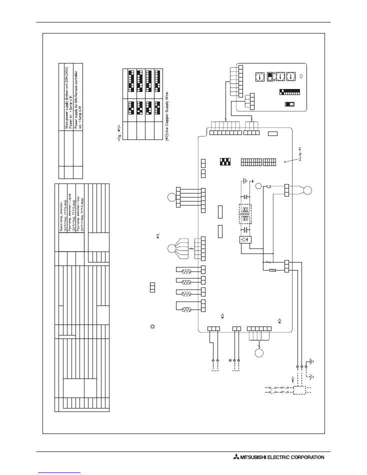
Note
1.At servicing for outdoor unit, always follow the
wiring diagram of outdoor unit.
2.In case of using MA-Remote controlle
r, please connect to
TB15.
(Remote controller wire is non-pola
r.)
3.In case of using M-NE
T, please connect to
TB5.
(
Transmission line is non-pola
r.)
4.Symbol [S] of
TB5 is the shield wire connection.
5.Symbols used in wiring diagram above are, :
terminal block, :connecte
r.
6.The setting of the SW2, SW3 dip switches di
ffers in the capacity for the detail, refer to the
fig
:
7.Please set the switch SW5 according to the power
supply voltage.
CN51
CN52
SW2
SW3
SW4
A.B
Address board
SW1
SW5
SW
11
SW12
Mode selection
Voltage selectio
n
Address setting 1st digit
Address setting 2nd digit
SW14
Connection No.
Centrally control
Remote Indication
Switch
Switch
Capacity code
Mode selection
Model selection
ZNR
Varisto
r
X1
Aux.relay
Drain pump
FUSE
Fuse (6
A / 250V
)
LED1
Power supply (I.B)
LED2
Power supply (I.B)
T
Transforme
r
TH21
MF
MV
Thermistor
LEV
Linear expansion valve
TH22
TH23
Fan motor (with inner thermo)
Vane moto
r
TB15
MA-Remote Controller
[Legend]
Symbol
Name
I.B
Indoor controller board
CN25
CN27
CN32
Connector
Humidifier
Damper
Remote switch
Symbol
Name
Symbol
Name
DS
DP
Drain sensor
Drain pump
TB2
TB5
Transmissio
n
Termina
l
block
Power supply
Models
P06
P08
P12
P15
SW2
1
2
3
4
5
6
ON OFF
1
2
3
4
5
6
ON OFF
1
2
3
4
5
6
ON OFF
1
2
3
4
5
6
ON OFF
SW3
1
2
3
4
5
6
7
ON OFF
1
2
3
4
5
6
7
ON OFF
1
2
3
4
5
6
ON OFF
1
2
3
4
5
6
7
7
8
8
8
8
9
9
9
9
10
10
10
10
ON OFF
Mark
Meaning
Function
Power supply for MA-Remote controller
LED on indoor board for service
LED1
Main power supply
LED2
1
2
3
4
5
5
6
MF
FA
N
(WHT
)
LED2
LED1
2
1
(BLU) (M-NET) CN2M
BLU
BLU
TB5
M1
M2
TB2
PUL
L BO
X
FUSE(15A)
BREAKER (15A)
L1
L2
S(
SHIELD)
TO OUTDOOR UNI
T
BC CONTROLLER ME REMOTE CONTROLLER DC24-30V
2 3
1
CN3A (BLU)
ORN
ORN
TB15
1
2
TO MA-REMOT
E
CONTROLLER DC8.7-13V
POWER SUPP
LY
~ / N 208-230V 60Hz
TO NEX
T INDOOR UNI
T
3
2
1
(BLK) GAS CN29
2
1
(WHT) LIQUID CN21
2
1
DS
TH23
TH22
(RED) IN
TAK
E
CN20
(WHT) LEV CN60
(GRN) REMOTE
INDIC
ATIO
N
CN52
2
1
6
5
4
3
2
1
1
5
(GRN) V
AN
E
CN6V
6
5
4
3
2
1
2
1
1
2
3
4
5
TH21
(WHT) DRAIN CN31
6
LEV
MV
CN25
2
1
CN27
8 7 6 5 4 3
4 3
3
2 1
1
2 1
12
34
56
78
910
SW3
12
34
56
SW2
12
34
5
SW4
ON
OFF
ON
OFF
ON
OFF
(RED)
ADDRESS
CN81
(RED)
ADDRESS
CN42
(WHT)
REMOTE SWITCH
CN32
3
2
1
2
1
3
DP
X1
X1
(WHT) CNP
CND (RED)
FUSE 250V
6A
T
BRN
RED
ORN
YLW
GRN
BLU
BRN
ORN
YLW
RED
WHT
(WHT)
CENTRAL
LY
CONTROL
CN51
1
5
RED
BLU
GRN
/ Y
LW
8
7
6
5
4
3
2
1
4
3
2
1
8
4
0
SW14
SWC
CONNECTION
No.
0
SW11
1ST
DIGIT
0
SW12
2ND
DIGIT
3RD
DIGIT
12
34
56
78
910
SW1
SW5
230V
208V
(RED)
ADDRESS
CN82
(RED)
ADDRESS
CN43
A.B
I.B
G
PMFY-P06,08,12,15NBMU-ER5
Drw. : IU-BH79C630
4. ElECtRiCal wiRiNg diagRaMs
PMFY-7
2012 PMFY-P-NBMU-ER5 (October 2012)
© 2012 Mitsubishi Electric US, Inc.
27-30-33-35
32-34-36-37
Operating sound levels
(Low-Medium2-Medium1-High)
PMFY-P06NBMU-E
PMFY-P08NBMU-E
32-34-36-37
33-35-37-39
PMFY-P12NBMU-E
PMFY-P15NBMU-E
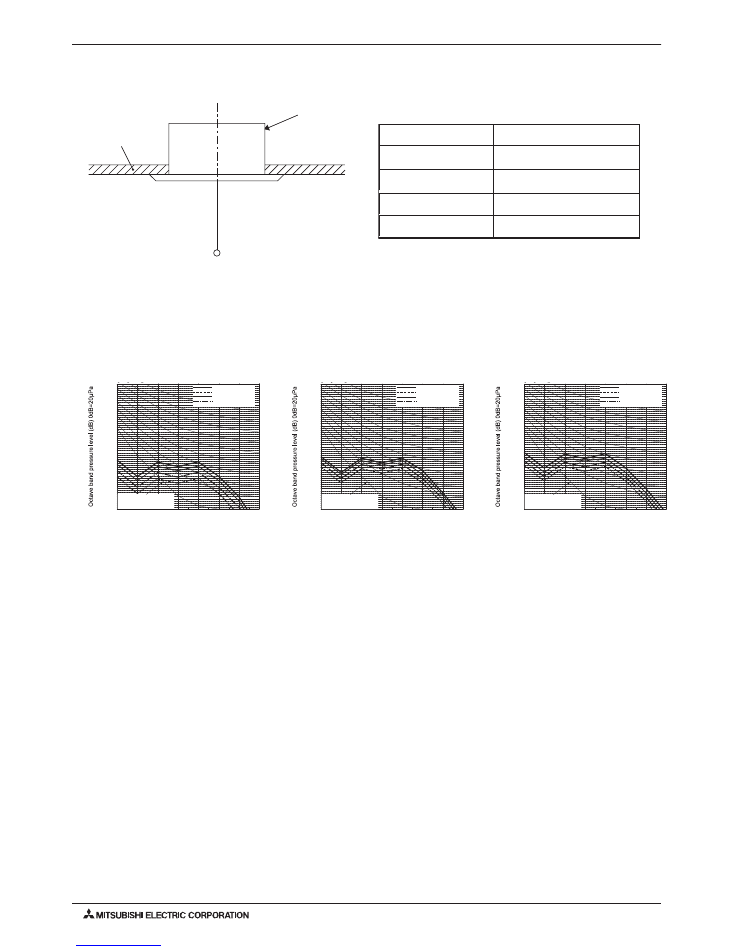
Sound levels (A weighted)
Model
Unit : dB(A)
Ceiling cassette series
UNIT
(1.5m)
MICROPHONE
CEILING
Measurement location
4-
7/ 8 ft
5-2. NC Curves
5. sOUNd PREssURE lEvEls
5-1. sound Pressure levels
PMFY-P06NBMU-ER5
External Static Pressure: 0Pa [0.00 in.WG]
Power Source: 208-230V, 60Hz
10.0
15.0
20.0
25.0
30.0
35.0
40.0
45.0
50.0
55.0
60.0
65.0
70.0
63
125
250
500
1k
2k
4k
8k
NC-60
NC-50
Approximate minimum
audible limit on
continuous noise
NC-40
NC-30
NC-20
Octave band center frequencies <Hz>
High
Low
60Hz
Middle1
60Hz
Middle2
60Hz
60Hz
Ref.:NC_PMFY-P06NBMU-E
27-30-33-35
32-34-36-37
Operating sound pressure levels
(Low-Medium2-Medium1-High)
PMFY-P06NBMU-ER5
PMFY-P08NBMU-ER5
32-34-36-37
33-35-37-39
PMFY-P12NBMU-ER5
PMFY-P15NBMU-ER5
Sound levels (A weighted)
Model
Unit : dB(A)
PMFY-P08,12NBMU-ER5
External Static Pressure: 0Pa [0.00 in.WG]
Power Source: 208-230V, 60Hz
10.0
15.0
20.0
25.0
30.0
35.0
40.0
45.0
50.0
55.0
60.0
65.0
70.0
63
125
250
500
1k
2k
4k
8k
NC-60
NC-50
Approximate minimum
audible limit on
continuous noise
NC-40
NC-30
NC-20
Octave band center frequencies <Hz>
High
Low
60Hz
Middle1
60Hz
Middle2
60Hz
60Hz
Ref.:NC_PMFY-P08,12NBMU-E
PMFY-P15NBMU-ER5
External Static Pressure: 0Pa [0.00 in.WG]
Power Source: 208-230V, 60Hz
10.0
15.0
20.0
25.0
30.0
35.0
40.0
45.0
50.0
55.0
60.0
65.0
70.0
63
125
250
500
1k
2k
4k
8k
NC-60
NC-50
Approximate minimum
audible limit on
continuous noise
NC-40
NC-30
NC-20
Octave band center frequencies <Hz>
High
Low
60Hz
Middle1
60Hz
Middle2
60Hz
60Hz
Ref.:NC_PMFY-P15NBMU-E
PMFY-8
2012 PMFY-P-NBMU-ER5 (October 2012)
© 2012 Mitsubishi Electric US, Inc.
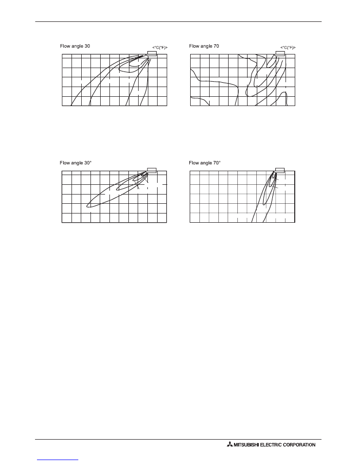
<Cooling mode>
Note : These figures show typical airflow distributions in the conditions above. In the actual installation, they may differ from
these figures under the influence of air temperature conditions, ceiling height, cooling/heating load,obstacles,etc.
°
<Heating mode>
°
2.7
(8' 10-
5
/
16
")
Height <m(ft)>
2
(6' 6-
3
/
4
")
1
(3' 3-
3
/
8
")
2.7
(8' 10-
5
/
16
")
Height <m(ft)>
2
(6' 6-
3
/
4
")
1
(3' 3-
3
/
8
")
4
(13' 1-
1
/
2
")
5
(16' 4-
7
/
8
")
3
(9' 10-
1
/
8
")
2
(6' 6-
3
/
4
")
1
(3' 3-
3
/
8
")
0
Floor distance <m(ft)>
5
(16' 4-
7
/
8
")
4
(13' 1-
1
/
2
")
3
(9' 10-
1
/
8
")
2
(6' 6-
3
/
4
")
1
(3' 3-
3
/
8
")
0
Floor distance <m(ft)>
25(77)
23(73)
21(70)
19(66)
23(73)
25(77)
25(77)
24(75)
27
(81)
30
(86)
21(70)
24(75)
33
(91)
ef.:T
F - -N
-
30
ef.:T
F - -N
-
H70
6-1. temperature distributions
6-2. Airflow Distributions
6. tEMPERatURE/aiRFlOw distRiBUtiONs
<Fan mode>
<Fan mode>
5
(16' 4-
7
/
8
")
5
(16' 4-
7
/
8
")
2.7
(8' 10-
5
/
16
")
Height <m(ft)>
2
(6' 6-
3
/
4
")
1
(3' 3-
3
/
8
")
2.7
(8' 10-
5
/
16
")
Height <m(ft)>
2
(6' 6-
3
/
4
")
1
(3' 3-
3
/
8
")
4
(13' 1-
1
/
2
")
3
(9' 10-
1
/
8
")
2
(6' 6-
3
/
4
")
1
(3' 3-
3
/
8
")
0
Floor distance <m(ft)>
4
(13' 1-
1
/
2
")
3
(9' 10-
1
/
8
")
2
(6' 6-
3
/
4
")
1
(3' 3-
3
/
8
")
0
Floor distance <m(ft)>
m/s(ft/s)
m/s(ft/s)
0.5(1' 7-
11
/
16
")
1.0(3' 3-
3
/
8
")
2.0(6' 6-
3
/
4
")
3.0(9' 10-
1
/
8
")
0.5(1' 7-
11
/
16
")
0.5(1' 7-
11
/
16
")
1.0
(3' 3-
3
/
8
")
2.0(6' 6-
3
/
4
")
3.0(9' 10-
1
/
8
")
ef.
F- -
-
30
ef.
F- -
-
70
ote hese fig res sho t
ical airflo distri
tions in the conditions a o e. n the act al installation the ma dif
fer from
these fig res nder the infl ence of air tem erat re conditions ceiling height cooling/heating load o stacles etc.
PMFY-9
2012 PMFY-P-NBMU-ER5 (October 2012)
© 2012 Mitsubishi Electric US, Inc.
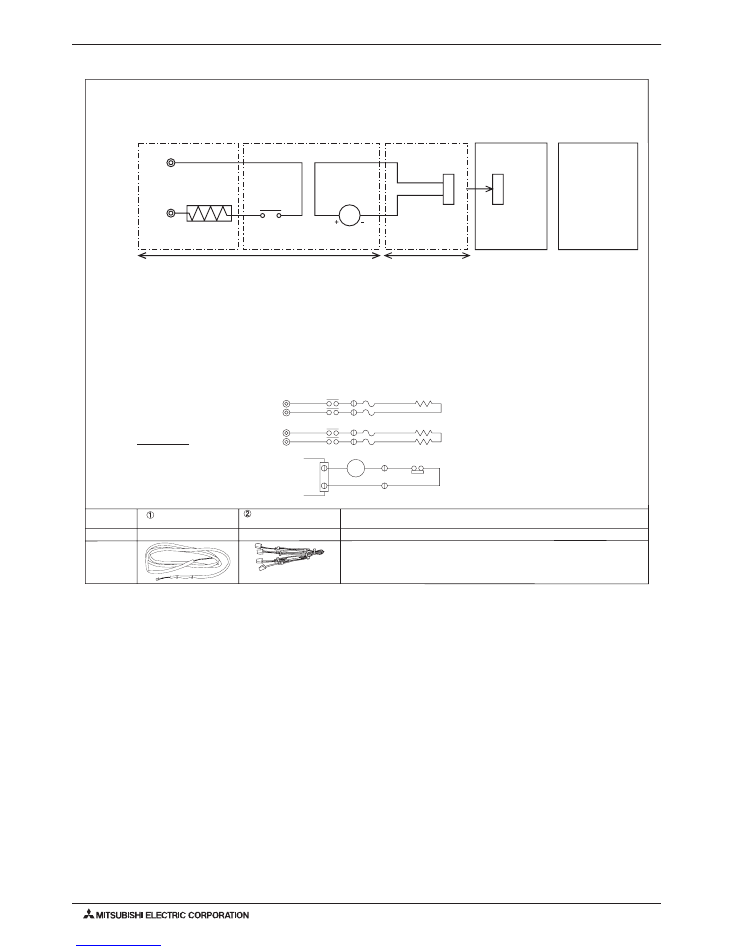
7. OPtiONal PaRts
7-1. External Heater adapter CN24RElaY-Kit-CM3
External heater adaptor CN24RELAY-KIT-CM3 is a set of special wiring parts for controlling the electric heater* with the air conditioner system.
*The electric heater should be designed and prepared at the site.
A basic connection method is shown as follows:(For details, refer to its Installation Manual.)
Item
External output cable
Fan speed setting cable
with resistance
Quantity
2
2
Shape
Refer to the Installation Manual for wiring and installation details.
For relay X use the specifications given below Operation coil
Rated voltage : 12VDC
Power consumption : 0.9W or less
The length of the electrical wiring for the CN24RELAY-KIT-CM3 is 2 meters (6-1/2 ft)
To extend this length, use sheathed 2-core cable.
Control cable type : CVV, CVS, CPEV or equivalent.
Cable size : 0.5 mm
2
~ 1.25 mm
2
(16 to 22 AWG)
Don't extend the cable more than 10 meters (32ft)
Recommended circuit
CN24
X
X
Remote control Board
Relay circuit
Adapter
Indoor unit
control board
Outdoor unit
control board
Electr
ic Heate
r
po
w
er source
Electric
Heater
Red
1
White 2
Preparations in the field
Maximum cable length
is 10 m (32ft)
Whit
e
FS1
FS2
FS1
FS2
R
S
R
S
CN24
H2
88H
H1
88H
26H
88H
Wiring diagram
1-phase power
supply
208V, 230V/60Hz
Control board
FS1, 2 ----- Thermal fuse
H1, H2 ----- Heater
26H --------- Overheat protection
thermostat
88H --------- Electromagnetic contactor
PUHY,PURY-P-TGMU
SW5-2 "ON"
PUHY,PURY-P-T/YHMU
SW5-10 "ON"
PUMY series
SW4-4 "ON"
PUHY,PURY-P-T/YJMU
SW5-10 "ON"
PUHY,PURY-HP-TJMU
SW5-10 "ON"

PMFY-10
2012 PMFY-P-NBMU-ER5 (October 2012)
© 2012 Mitsubishi Electric US, Inc.