Full Text Searchable PDF User Manual
READ THIS MANUAL
CAREFULLY
1.
FOREWORD – IDENTIFIC. AND MARKING PAG. 1
2.
CONDITIONS-USE - WARRANTY
PAG. 2
3.
SAFETY WARNINGS
PAG. 3-4
4.
START – WARNING/DRIVING SIGNS
PAG. 5
5.
DIMENSIONS – PACKAGE - TRANSPORT
PAG. 6
6.
CONTROLS – START-UP
PAG. 7
7.
SAFETY DEVICE–PRESSURE–CONTROLS PAG. 8
8.
HANDLEBAR ADJUSTM.- OIL REPLACEM. PAG. 9
9.
LUBRICATION – IMPLEMENTS
PAG. 10
10.
ROTARY HOES – MOWER BAR APPLIC.
PAG. 11
11.
ADJUSTMENTS – ASSEM./DISASSEMBLY PAG. 12
12.
USE OF MOTOR CULTIVATOR
PAG. 13
13.
MAINTENANCE AND USE
PAG. 14
14.
NOISE AND VIBRATIONS
PAG. 15
15.
DECLARATION
PAG.
16
GB
03/05
MOTOR CULTIVATOR MF 223 REVERSIBLE
USER’S MANUAL
1 - FOREWORD
INDEX
This symbol is used to highlight
an important safety information.
If this information is ignored,
people are in danger either of
possible injures – even serious
ones – or death.
IMPORTANT
This term highlights special
precautions to be taken in
order not to damage the
machine.
All right reserved
This manual cannot be
either reproduced or
released without
the manufacturer’s
prior written consent.
PRINTED IN ITALY
2 - MACHINE IDENTIFICATION AND MARKING
The machine serial number is printed on the drive box.
IMPORTANT NOTE
Always mention the machine serial number when calling
our technical service or when ordering spare parts.
MARKING
The CE mark is on the handle support as this example
Marking example.

This manual gives you general information on how this
machine should be used and maintained. For any
technical problem, please, call Your confidential dealer.
•
This machine has been designed to be used in
compliance with what specified in the machine
descriptions and safety warnings of this instructions
manual.
•
Any other use is not allowed. The manufacturer is
not responsible for damages caused by any use then
the intended use. The user is fully responsible for
any possible risk.
•
Use, maintenance and repair clauses prescribed by
the manufacturer are also integral part of the
machine intended use.
•
Only people familiar with this machine and well
aware of its hidden risks can use, repair and
maintain it.
•
The manufacturer is not responsible for damages
caused by non-authorized changes made on this
machine.
•
Besides warnings mentioned in this manual, please,
also comply with general regulations on safety and
accident prevention of EEC and the country in
which this machine will be operating.
3 - CONDITIONS AND USE
4 - WARRANTY
If in doubt on causes and possible solutions for a certain
trouble, please, call our authorized dealer.
This should be absolutely done during the warranty
period, since any repair made by non-authorized
workshops makes this warranty null and void.
Bear always in mind that the authorized dealer has all
special tools, technical specifications and spare parts
necessary for properly fixing the machine.
Therefore, he should be called in case of any doubt on
maintenance specifications and/or procedures. Some
pages of this manual might not be perfectly right due to
misprints or production changes. For this reason, call
Your dealer before being perfectly familiar with this
machine and personally maintaining this machine. For
further information on use and maintenance of this
machine, ask your authorized dealer for the proper
technical manuals.
Our materials have a 12 months warranty (coverings and
electrical parts are not included). The manufacturer
agrees on replacing those parts considered as faulty free
of charge. Purchaser will be charged with labour costs –
necessary for repairing the machine – and possible
transport costs. Both the warranty claim and the returned
piece should always be addressed to our Spare Parts
Department and accompanied by regular freight bill
mentioning all the machine details.
As far as materials available on the market – especially
engines – are concerned, regulations of our supplier will
apply and applications for possible technical service
should be addressed to the local specialized technical
service centres.
- 2 -

5 - SAFETY WARNINGS
1) This machine has been designed and manufactured for being used by one operator only, and is driven by
means of the appropriate handlebars. Any other use is not permitted.!
2) Before operating the machine, read the Use and Maintenance manual thoroughly, so that you are fully aware
of all the operating controls and safety aspects of the machine.
3) Do not under any circumstances transport people or objects on the machine.
4) Always ensure that the machine’s safety devices are correctly mounted and in perfect working condition..
5) Before use, check that all the controls, in particular the clutch, the motor stop and the brakes (if fitted9are in
good
working order.
6) Any modifications or spurious parts being fitted without the Manufacturer consent will nullify the guarantee,
and any possible resulting damage will not answered for.
7) This machine must not be used by children or inexperienced persons.
8) Before operating the machine, check that the area is clear and free of debris and that there are no people
within the working area (danger zone). The operator, will be held responsible for the safety of third parties, if
these are found within the working area of the machine. Do not use the machine under these conditions.
9) keep clear of cutting blades at all times while the machine is in operation. Pay particular attention when
reversing; keep hands and feet clear.
10) Use the machine only with the handles in the correct working position. This allows a safe working distance
between the operator and operating area.
11) Use only original accessories and spare parts to guarantee safety and correct operation of the machine.
12) Stop engine before refuelling and remove ignition key (if fitted).
13) Handle the fuel with care to avoid spilling on the machine; clean any spillage immediately.
14) Never refuel in confined places, in vicinity of open flames or near the source of sparks. No smoking!
15) Before starting the engine, check that all the controls are in the idle position.
16) Do not smoke when starting the engine!
17) Do not run the machine in a confined area as toxic exhaust gas can kill.
18) Plan your work before commencing.
19) Do not use the machine when you are tired.
20) Engage the clutch gradually; sudden engagement could cause the machine to rear up.
21) The area next to the engine exhaust will most likely reach temperatures above 80
°. Attention
! Danger of
scalding.
22) Always wear close fitting clothes and anti-slip shoes or boots. For safety reasons avoid using loose clothing.
- 3 -

23) Make regular checks that all bolts and nuts are well tightened.
24) Keep the area of work clear and clean.
25) Only use the machine in clear visibility.
26) Avoid working with blunt cutting blades. .
27) Pay maximum attention and use good sense when operating the machine.
28) If you hit any objects during work, stop the machine and check for any damage immediately.
29) During movement to and from the area of work, disengage the Power Take Off. (P.T.O).
30) Pay attention when reversing the machine not to trip over anything. If you loose your balancer, release the
handlebars immediately; the Motor stop or the disengagement will immediately stop the machine.
31) Do not under any circumstance attempt to by-pass the motor-stop device or remove the disengagement
device. The machine would result having no safety precautions and would be extremely dangerous.
32)Do not travel down hill with the clutch disengaged or the gears in idle.
33) The machine’s speed must always suit the conditions and the environment.
34) Do not perform cleaning or maintenance operations of the machine when the engine is running.
35) Avoid sharps turns when travelling up hill, down hill or across steep slopes.
36) In steep descents, do not disengage the drive and do not change gear.
37) When possible, avoid working up or down hill .Always travel across the slope.
38) Do not work on very steep slopes (max.30%).
39)Avoid overfilling the fuel tank.
40) If there is fuel in the tank, avoid tilting the machine during maintenance or adjustment.
41) During use, keep the hot sections of the engine (i.e. cylinder head, exhaust, etc.) clean to avoid a build up of
debris that will overheat the engine.
42) Whenever possible, stop the machine on level ground.
43) When stopping on unlevelled ground, engage 1stgear (up hill) or reverse gear (down hill).
44) If leaving the machine for a long time, ensure it is inaccessible to children and inexperienced people. Close
the fuel tap (if fitted).
45) Do not leave the machine with the engine running.
46) The maintenance instructions of the machine must always be carefully followed and worn parts replaced
when necessary.
47) If the machine is to remain unused for some time, clean it accurately and insert the appropriate protections.
48) Apart from the previous items, it is necessary to take heed of the specific safety norms in force in the
Country where the machine is operating.
- 4 -
6 - MACHINE START
READ CAREFULLY THE WHOLE MANUAL BEFORE STARTING THIS
MACHINE.
NOTE:
The manufacturer aims at ever improving both design and quality of his products. As a consequence, even though this
manual includes latest and most up-dated information available when printed, there might be small differences between
your machine and the information of this manual. For any doubt or uncertainties on this manual, please call our
authorized dealer. This manual is integral part of this machine and should always accompany this machine when sold.
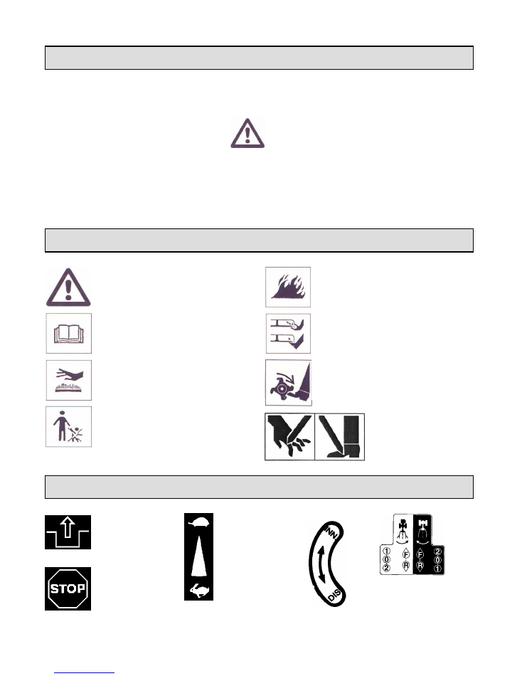
7 - WARNING SIGNS
“DANGER”
Fire risk.
“WARNING”
Comply with what
specified in safety warnings and warning
signs.
Read use instructions !
“DANGER
” Blades and rotating parts in
operation. Keep hands and feet away.
“DANGER”
Risk of burns
“DANGER”
Blades and rotating parts in
operation. Keep hands and feet away.
“DANGER”
Keep children away from
the machine.
“
DANGER
” due to working
knives and mowing bars!
Keep hands and feet away
from them.
8 - DRIVING SIGNS
ACCELLERATOR
HANDLE
ENGAGEMENT
DISENGAGEMENT
STOP
DISENGAGEMENT
ENGAGING
GEARS
- 5 -
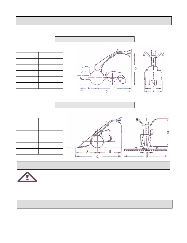
9 - OVERALL DIMENSIONS
MOTOCULTIVATOR VERSION
A 510
B 1225
C 1735
D 410-1240
E 450
F 400-500-600
MOWER VERSION
A 830
B 930
C 1760
D 410-1240
E 450
F 1070-1170
10 – PACKAGE OPENING
CRUSHING DANGER
NB: WEIGHT OF THE MACHINE 93 KGS.
-
Open the carton in its upper side. –Remove the bare machine and wheels to be assembled
to the same. -
ATTENTION
: use a lifting system to take the machine out of the carton
according to its weight and follow closely the safety and assembling rules on pages 9/10 .
11 - TRANSPORT
Always insert the appropriate blade protection (if in mower version).
When loading the machine into a lorry, use ramps of adequate stability and strength, or otherwise secure the machine on a
pallet and lift with an elevating trolley with the forks at the maximum possible opening.
- 6 -
12 - CONTROLS
1
6
7
3
5
IMPORTANT !
1.
Engine stop lever
2.
Clutch control lever
3.
Handlebar vertical lock lever
4.
Steering column horizontal lock lever
5.
Forward and reverse gear control lever
6.
Throttle control lever
7.
P.T.O. control lever
8.
Gear control lever
9.
Wheels disengagement lever
4
1
1
2
9
3
7
8
8
5
MOTOCULTIVATOR
MOTOMOWER
13 – ENGAGING GEARS
The motocultivator has 4 speed gearbox (2 forward + 2 RV) selected
by levers 5 and 8.
•
With handlebars in tilling position (white symbols on the plate)
:travel direction is selected with lever and the 1
st
and 2
nd
speed are
selected with lever 8.
•
With handlebars in front implements position (black symbols on
the plate): travel direction is selected with lever 5, and the 1
st
and
2
nd
speed are selected with lever 8.
ATTENTION
– To avoid unnecessary strain on the controls, make
sure that the P.T.O. is in idle position before engaging the reverse
gear (and vice versa).
N.B.: Use the clutch to make speed engagement easier. In order to
make the engagement of the direction selector easier, set the engine at
minimum running and operate the lever without using the clutch..
Avoid a protracted clutch disengagement in order to limit the wear of
the thrust bearing.
14 – ENGINE START-UP
3
2
- 7 -
When starting the engine, follow the
instructions contained in the engine’s “Use
and Maintenance” booklet, and after having
made sure that the gear control and P.T.O.
control levers are in idle position, lock the
motor stop lever 1 and clutch lever 2 by
using hook 3.
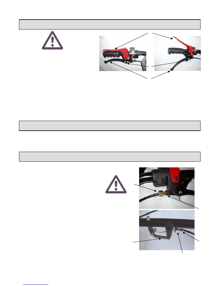
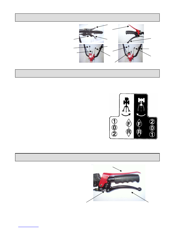
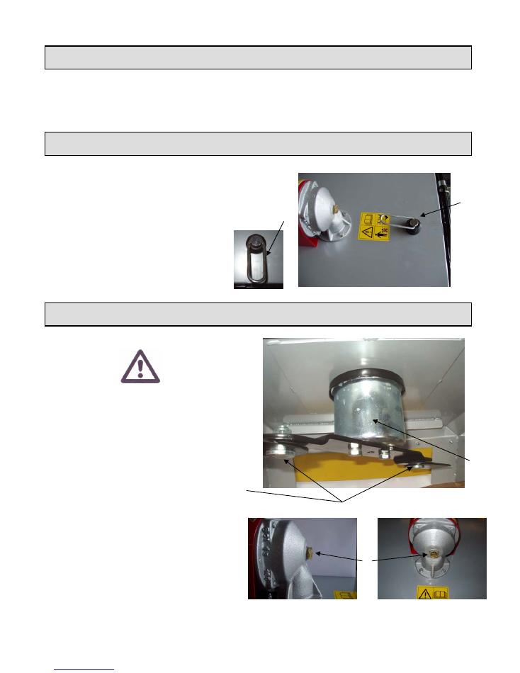
15 – ENGINE STOP SAFETY DEVICE
Often check that tyre pressure be within the limits of 1 – 1,2 Bar .
Main function of lever
“1”
is the engine to
be stopped when handlebars are left away.
Do not tie the engine stop lever “1” to the
handlebar handle..
Each time the engine is started, check that
the safety clutch
“3”
is into lever
“2”.
ENGINE STOP
: lever
“1”
up.
ENGINE RUNNING
: lever
“1”
down.
BEFORE USING THE MACHINE IT IS IMPORTANT TO
VERIFY WITH CLOSE ATTENTION THAT SAFETY
DEVICES ARE ALL WELL WORKING.
1
3
2
16 – TYRE PRESSURE
17 - CONTROLS ADJUSTMENT
CLUTCH:
Check the idle stroke of the
clutch lever regularly. This should be
approximately 5mm
•
In order to change adjustment , loosen
nut 5.
•
Set stroke to about 5mm by screwing or
unscrewing adjuster 4.
•
Lock nut 4 again..
POWER TAKE OFF CONTROL LEVER:
Periodically check the idle stroke of lever 8.
To change adjustment loosen nut 6 and
screw or unscrew adjuster 7. Then lock nut 6
again.
4
5
8
7
6
- 8 -
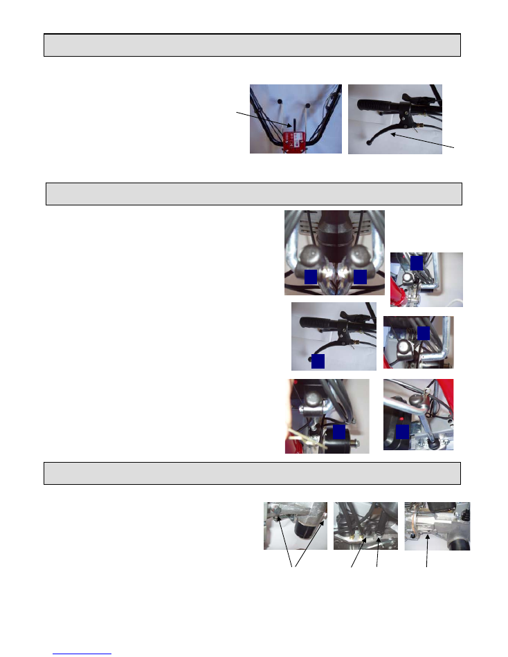
18 - HANDLEBARS
Adjustment in height (vertical sense) allows 5
positions, obtained with lever 9.
Side adjustment (horizontal sense) allows 6
positions (3 with handlebars in normal
positions + 3 with handlebars reversed by
180°) which are obtained with lever 10.
9
10
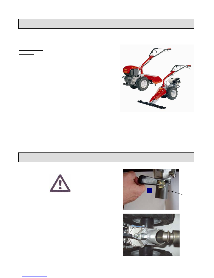
19 - ROTATION OF HANDLEBAR
In order to turn handlebars and to utilize the machine as
motor mower , please follow the below instructions:
1.
Take away cotter pins 11 and 12 and free laterally
the rods out from their position – see 13.
2.
Keep rods moving them towards levers of the
handlebar.
3.
Pick lever 10 and turn the handlebar by 180° as
indicated on the sticker placed on the handlebar
itself.
4.
Reach the right position, leave lever 10 after
putting the block system . The handlebar support
must not move.
5.
Put again rods in their previous position – see 14 -
and at last their cotter pins -15-.
12
11
13
13
10
13
14
15
20 - GEAR BOX OIL AND CLUTCH OIL REPLACEMENT
Oil must be replaced when hot by unscrewing fill caps A
and taking fill caps B and C away. When oil is completely
drained, replace caps A and fill with new oil through hole
B (clutch oil) and C (gear box oil) up. Check the clutch oil
level by using screw D and the gear box oil level by using
fill cap C equipped with a dipstick. This operation is to be
done with motor cultivator in horizontal position.
A
C B
D
- 9 -
21 - LUBRICATION
TYPE OF LUBRICANT
Engine: see engine manual.
Motor cultivator:
Oil replacement: AGIP ROTRA MP 80W/90
Clutch oil: AGIP ROTRA MULTI THT
1.
ENGINE
Each day: check level and top up if necessary.
Oil replacement: to be carried out according to intervals and
methods set out by the engine manufacturer.
2.
GEARBOX
Every 200 hours: check level and top up if necessary.
Every 500 hours : replace oil.
3.
POWER TAKE-OFF FOR IMPLEMENTS
Before attaching implements, fill up with multipurpose grease
AGIP GREASE MU EP 0.
4.
ROTARY HOE BOX
Every 200 hours: check level by unscrewing the cap of the rear
cover of the rotary hoe body. Replace if necessary.
Every 500 hours: replace oil (oil AGIP D. SIGMA SAE 30).
5. MOWING BAR BOX
Oil: AGIP ROTRA MP 80W/90
6. ROTO-MOWER BOX
Oil: AGIP SIGMA SAE 30
IMPORTANT !
22 - IMPLEMENTS COUPLING
16
To be greased
periodically
The machine is equipped with a quick implement
connection.
Before mounting the implement, make sure that the
P.T.O. engagement lever is in idle position.
When connecting or disconnecting the implements, it
is necessary to pull the knob 16 upwards and engage
the implement in the connection sleeve 17 and bring
the knob back to its original position. Make sure that
the shutter has gone into the stop hole.
17
- 10 -
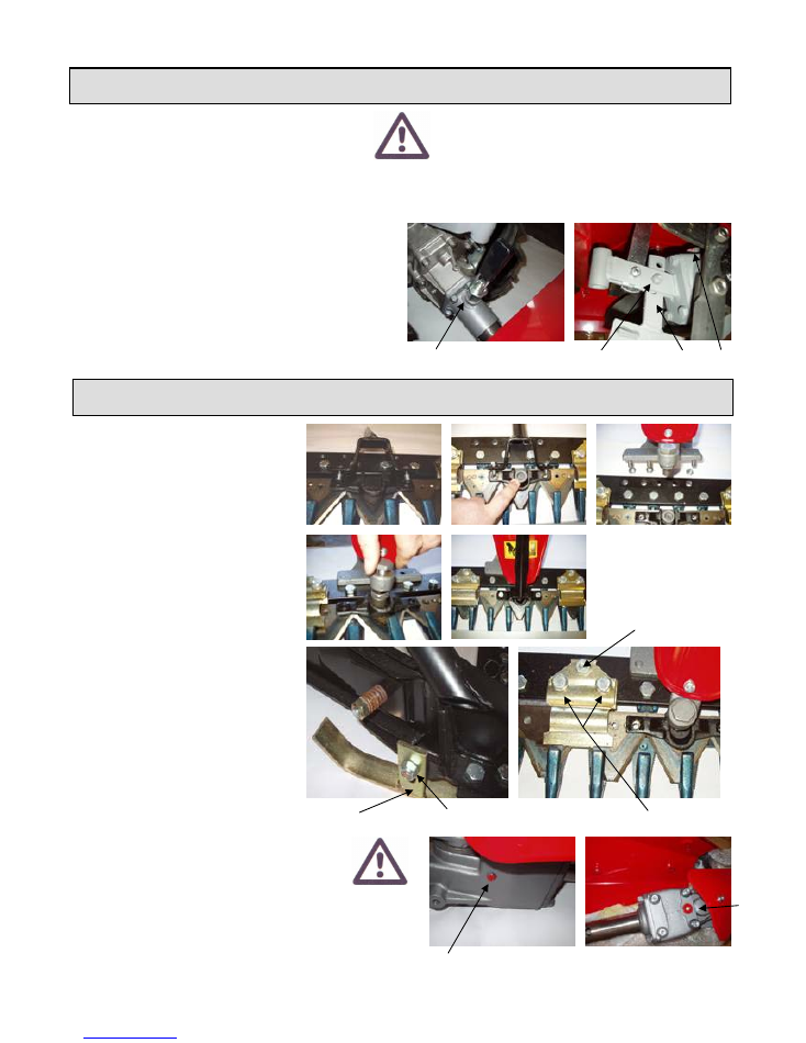
23 - ROTARY HOES
ROTARY HOE MAINTENANCE
ATTENTION – Maintenance operations must be
carried out with machine at standstill and engine
switched off. !
Each time the Rotary Hoe is used check that:
1.
The bolt Pos.1 is turned until it trips into gripped
position.
2.
The blade’s nuts and fixing screws are well
tightened.
3.
The oil of the valve collets box is at right level -0-
PIC. 3
IMPORTANT !
At first fit the transmission set to the
mowing bar (don’t forget the bushing)
following the side pictures.
Connection to the motor cultivator
The mower bar is attached to the motor
cultivator by means of the Quick fit
connection.
Mower-height adjustment
•
Loosen nut (1).
•
Bring the skid pad (2) back to
wanted position.
•
Lock the nut again.
•
Carry out adjustment on both skid
pads.
Blade holder adjustment
•
Loosen fixing screws (3).
•
Move the adjustable screw (4).
•
Lock the fixing screws again.
•
N.B.
: for a good work there must not be
too much rubbing between the blade-
holder and the blade itself around 0,1 –
0,2 mm. play.
PIC. 1
4
3
2
1
PIC. 5
PIC. 4
PIC. 2
24 - FRONTAL MOWER BAR APPLICATION
TECHNICAL CHARACTERISTICS:
Hood width: 40 – 50 – 60 cm.
Hoe diameter: 260 mm. N°blades:24
Working depth adjustment: in order to vary the working depth, adjust the central hoe’s inclination by removing
fixing screw (2) and shifting the perforated rod (3) until it meets a new hole. When working with hard terrain, to
prevent the machine from bounding forwards, adjust the central knife by moving it downwards into the last hole.
1
2
3
0
Check the oil level of the swinging ass.ly through the screw
“5” each 8 working hours and lubricate the blade bush “2”.
Top up with oil through the plug on the swinging ass.ly
part “6”, if necessary. Use oil AGIP ROTRA MPS SAE 85
W/90.
- 11 -
6
5
25 - FRONTAL ROTATING MOWER SET
CONNECTION TO THE MOTOCULTIVATOR
The rotating mower set is attached to the motor cultivator by means of the Quick Fit connection.
26 - CUTTING HEIGHT ADJUSTMENT
Cutting height is easily adjusted by tightening or
loosening the lever “
15
”.
27 - BLADE ASSEMBLY AND DISASSEMBLY
The blade can be easily removed by unscrewing the
two screws “16”;, to reassemble it, clean the cutter
hub “17” thoroughly and tighten the screws as far as
they are fully secured and cutting blades turn freely.
N.B.: Always change self blocking nuts with new
ones.
Check the mower set oil level every 200 hours
through the screw “18”. Add oil, if necessary.
Use oil SIGMA SAE 30.
AFTER 500 h. change whole oil.
15
15
18
IMPORTANT !
17
16
- 12 -

28 - USE OF THE MOTORCULTIVATOR
RUNNING-IN
During the first 80 hours of operation the following standards must be observed:
•
After every start from cold, run the engine slowly for some minutes without load.
•
Do not operate the engine at low speed for a long time.
•
Do not use the machine for long periods in heavy works.
•
Frequently checks that there are no oil losses and replace it the first time as suggested by the producer.
BEFORE STARTING THE ENGINE
Every day, before starting the engine, check:
•
The oil level in the engine sump.
•
The quantity of the fuel in the tank.
STARTING THE ENGINE
Verify that all the safety devices are perfectly working and inserted before engine starting up.
•
Make sure that all control levers are in neutral position.
•
Start the engine following the instruction listed in this instruction book.
•
With the engine cold, avoid abrupt accelerations.
•
If environmental temperature is low, do not use the machine under stress immediately.
USE OF CONTROLS
•
When using the motor cultivators controls, carefully comply with the standards
contained in this instruction book
.
CHECKS DURING USE
•
In case of incorrect operation of any part , stop the machine and take the necessary steps.
•
Excessive smoking at the exhaust may denote some irregularity in engine operation; consult the
instruction book or the engine.
ACCELERATOR
•
Do not use the engine at too low speed; this can lead to excessive oil consumption and other troubles.
•
Low speed is however necessary when engages are done, to avoid problems of mechanical nature.
SPEED CHANGING
•
The motor cultivator can generally be started in any gear. It is therefore advisable to start
working by immediately engaging the gear which allows traction speeds suitable for the work to be made.
N.B.: To avoid mechanical problems all engagement actions have to be done with the engine at low speed.
- 13 -

29 - MAINTENANCE OF THE MOTOR CULTIVATOR
ATTENTION!: Effect the maintenance operations when the motor cultivator is stopped and the engine shut-down.
GENERAL STANDARDS
•
To ensure constant efficiency of the motor cultivator and increase its life, carefully comply with the maintenance
operations described in this instructions manual.
•
The intervals established for each operation must be carefully observed, otherwise it may endanger the operation
and performance of the motor cultivator.
•
It is advisable to clean the machine every week, removing all dust, mud and other dirt that may have
accumulated.
•
For lubrication of the various components use only the products indicated in this instructions manual.
•
Checking the oil level in the different machine members must be carried out with machine cold and on the flat.
•
Oil changes must be made with hot oil; this facilitates drainage and favours the removal of deposits..
•
Carefully clean the greasers before putting grease in them; clean them again when the operation is completed in
order to avoid accumulation of dust.
ENGINE AND RELATED MEMBERS
Carefully comply with the maintenance instructions contained in the respective instructions book.
TYRES
•
The inflation pressure value is shown in this instructions manual.
•
A pressure lower than normal causes irregular wear of the tread, favours wear of the sides of the tyre and may, in
extreme cases, lead to sliding of the tyre on the rim with consequent bursting of inner tube.
•
Pressure higher than normal favours skidding of the tyre on the ground, with consequent loss of traction and wear
of the tread.
•
The pressure must be checked with the tyres cold.
•
Avoid bringing the tyres into contact with oil, grease or fuel.
•
Periodically check the conditions of the tread; remove stones, nails etc., which may become embedded.
30 - USE OF INTERCHANGEABLE ACCESSORIES
For the use, in safety conditions, of the motor cultivator, is necessary use the interchangeable accessories from the
Manufacturer. Use of accessories from other Manufacturers must be approved from the Technical Office of
Manufacturer with written permit.
31 - LONG INACTIVITY OF THE MOTOCULTIVATOR
When the motor cultivator has to remain inactive for a long period of time, take the following precautions:
•
Protect the engine as indicated in the appropriate instruction book.
•
Carry out general cleaning of the machine and place it in a suitable place (neither dusty nor dump).
•
Lubricate the machine (see this instructions manual).
•
If possible, raise the machine from the ground, arranging it on suitable trestles..
•
Cover the machine with a protective tissue .
- 14 -

32 - NOISE AND VIBRATIONS
Weighed equivalent steady acoustic pressure level at the driving place at 1 m from the handlebars and a height of 1.6
m from the ground.
MODEL
dB(A) max. VALUE
ENGINE
OTHER VALUES
Acoustic power level.
MODEL
dB(A) MAX.VALUE
ENGINE
OTHER VALUES
Frequency weighed root mean square of vibrations at handlebars.
Integration time 60 sec. Weighting in compliance with ISO 5349.
MODEL
m/sec. 2 MAX VALUE
ENGINE
OTHER VALUES
MOTOCULTIVATOR VERSION
Descriptions, figures and technical features mentioned herein are non-binding for the Manufacturer. These are mentioned as mere information. The
Manufacturer reserves the right to make any change at any time without being bound to update this publication.
Weighed equivalent steady acoustic pressure level at the driving place at 1 m from the handlebars and at a height of
1.6 m from the ground.
MODEL
dB(A) MAX VALUE
ENGINE
OTHER VALUES
Acoustic power level
MODEL
dB(A) MAX VALUE
ENGINE
OTHER VALUES
Frequency weighed root mean square of vibrations at handlebars.
Integration time 60 sec. Weighting in compliance with ISO 5349.
MODEL
m/sec. 2 MAX VALUE
ENGINE
OTHER VALUES
MOWER VERSION
Copyright of MECCANICA BENASSI S.P.A.
- 15 -
33 - DECLARATION
- GB - CE – DECLARATION OF CONFORMITY
In compliance with CEE 89/392 regulations and subsequent
changes
- CERTIFICATE OF ORIGIN -
140002001
From series-no.*:
MF 223
Model:
MECCANICA BENASSI S.p.A ,
I-44040 DOSSO (FE) via Statale , 325
DECLARES ,under is own responsibility, that the item called
MOTOR CULTIVATOR
is manufactured by the above company in compliance with basic safety and health
safeguard requirements specified in the regulation CEE 89/392 and subsequent changes.
* The number is printed on the machine’s gearbox .
For checking the conformity with the above regulations, have been examined the following
CEN rules: UNI EN 709:98/A1 : 2000 .
Dosso, (Italy) , the 24th March , 2005 MECCANICA BENASSI SPA
L’Amministratore Unico
U.T. 24/03/05
- 16 -