Full Text Searchable PDF User Manual
1. Safety Instructions
Operation Manual
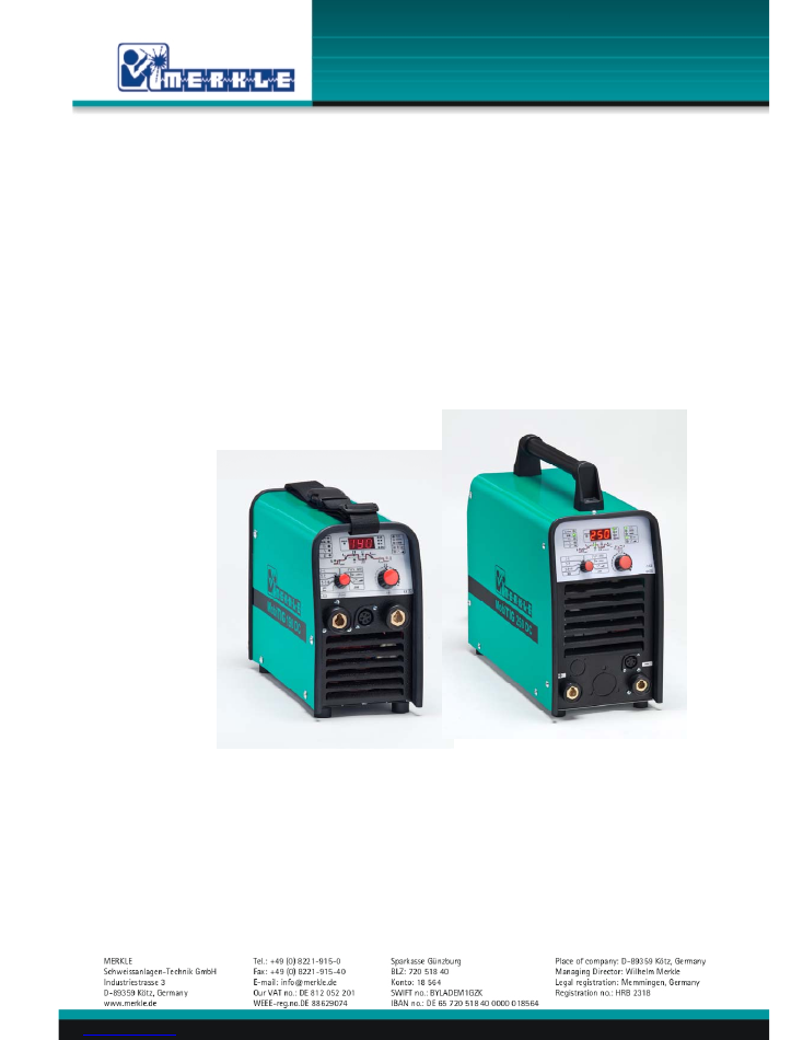
TIG-welding units
model MobiTIG 190 DC
model MobiTIG 250 DC

1. Safety Instructions
Security indications before introduction
The unit device is built after the recognized standards. Safe works are nevertheless only possible if
you read the operating instructions and the safety regulations contained in it entirely and obey
strictly. Install yourselves by trained staff of our establishments or appointed dealers.
Accident prevention regulations
The following accident prevention regulation is applied for welding unit, model TIG 160DC.
BGV D1 (earlier VBG 15)
*
Welding, cutting and allied processes.
A copy of this regulation should be readily accessible in every welding shop. The stipulations of
this regulation are to be observed in the interests of safe and correct welding operation.
* Available from the trade association responsible or
Carl Heymanns-Verlag, Luxemburger Strasse 449, 50939 Cologne.
Safety instructions
This unit is manufactured according to the requirements and stipulations of EN 60974.1 / VDE
0544 part 1. BGV D1 (earlier VBG 15) of the trade association for precision engineering and
electrical engineering are as well valid.
1) In case of an accident, the cutting unit must be disconnected from the mains immediately.
2) If electrical contact voltages arise, switch off the unit immediately, disconnect it from the
mains and proceed to inspection by a qualified electrician or by our Service Department.
3) Before opening the unit, disconnect it from the mains supply.
4) Repair work may only be carried out by a skilled electrician or by our Service Department.
5) Before the unit is put to operation, check it visually, as well as the torch and all cables and
connectors regarding possible external damages.
6)
Personal protective equipment in accordance with DIN EN 175, DIN EN 379 and
DIN EN 169.
During the work, the welder’s body must be completely protected against radiation and
burns by means of protective clothing and face protection. Long gloves, aprons and
welding shields with welding filters conforming to DIN EN 470-1 and BGR 189
must be worn.
Synthetic clothing are excluded. Shoes must be closed, not opened (due to spatters). If
necessary, protective headwear must be worn (e.g. for overhead welding). If cover glasses
are used, these must be in accordance with the norms specified above.
As additional protection for the eyes against UV radiation, safety goggles with side shields
and corresponding face protection in accordance with BGR 192 and BGI 553 must be worn.
Accident prevention regulation BGV D1 § 27 stipulates that it is the responsibility of the
employer to provide suitable personal protective equipment, while § 28 stipulates that it is
the responsibility of the insured to wear suitable clothing.

1. Safety Instructions
7) Protection when welding under increased electrical risks
Welding rectifiers and welding power sources which can optionally be used for either
direct or alternating current must be marked
"S"
in accordance with EN 60974-1 and BGI
534.
Use insulating materials to protect you against contact with electrically conductive parts
and damp floors. Wear dry, undamaged work clothing, long gloves and footwear with
rubber soles. Ventilate rooms, install extraction systems if required, and wear respiratory
protective equipment if necessary (see Procedural instructions BGV D1 § 27 and BGI 533,
Section 5).
8)
In order to prevent stray currents and the effects thereof (e.g. destruction of electrical
protective ground conductors), the welding return cable (workpiece cable) must be
connected directly to the workpiece to be welded or to the table (e.g. welding table, grid-
type welding table, workbench) supporting the workpiece (see BGV D1 § 20). When
installing the ground connection, assure that there is a good electrical contact (remove
rust, paint, etc.).
9) During welding pauses, the welding torch is to be laid down on an insulated surface or
hung up in such a way that it is not in contact with the workpiece and its support
connected to the welding power source (see § 20 BGV D1).
In the case of longer work pauses, the welding unit must be switched off and the gas
cylinder valve must be closed.
10) The shielding gas cylinder must always be protected against tumbling downing using a
safety chain.
11)
Under no circumstances the unit may be put into operation while it is opened
(e.g. for repair work). Apart from the safety regulations, sufficient cooling of the
electrical components provided by the fan cannot be guaranteed.
12)
In accordance with BGV D1 § 5, people in the vicinity of the arc must also be informed of
the hazards and protected against them. Safety partitions (“welding safety curtains”) must
be erected in accordance with DIN EN 1598.
1
3
)
N
o
welding work may be carried out on containers in which gases, fuels, mineral oils or
similar substances have been stored
Ö
even if they have been empty for a long time
Õ
(risk of explosion). See § 31 of accident prevention regulation BGV D1.
1
4
)
Welds which will be subjected to high loads and which need to meet specific safety
requirements may only be carried out by specially trained and qualified welders.
15) Never bring the torch close to your face.
16)
In areas at particularly high risk of fire, the welder must obtain a welding permit and have
this on his person throughout the duration of the welding work. On completion of welding,
a fire-guard must be delegated to ensure fire protection.
17)
Ventilation measures must be applied in accordance with BGI 553, Section 9.
18) The hazard to eyesight must be indicated by means of a sign at the work site
"CAUTION!
Do not look into the arc!"
.

1. Safety Instructions
Duty cycle
The duty cylce measurings have been carried out in accordance with
EN 60974-1 / VDE 0544 part 1 (10 min working period).
60% duty cycle means:
After a 6 min. welding period a 4 min welding pause must be respected. The electrical components
are thermally protected against overheating.
Instructions to avoid interferences due to electromagnetic influences EMC
The welding unit has been manufactured in accordance with the requirements of guideline
EN 60974-10 / VDE 0544 part 10 regarding electromagnetic compatibility. It is nonetheless the
responsibility of the user to ensure that the welding equipment is installed and operated in
accordance with the manufacturer’s instructions. If electromagnetic interference is detected, it is
the responsibility of the user of the welding equipment to find a solution with the technical
assistance of the manufacturer. In some cases, it may be sufficient simply to ground the welding
current circuit. In other cases, it may be necessary to build a complete shield for the welding
power source and workpiece using the input filters. In all cases, electromagnetic interference must
be reduced to avoid any possible malfunctions.
Note:
For safety reasons, the welding current circuit may or may not be grounded. No
modifications may be made to the grounding without the approval of an expert who is able to
determine whether the changes might increase the risk of accidents, e.g. by allowing parallel
welding current return paths which could destroy the ground conductors of other equipment.
Further instructions are contained in TEC 974-XX "Arc welding equipment – installation and use".
a)
Evaluation of the installation site
Before installing the welding equipment, the user must evaluate potential electromagnetic
problems in the vicinity. The following must be taken into consideration:
¾
Other power cables, control cables, signal and telecommunication cables above, below
and next to the welding equipment
¾
Radio and television transmitters and receivers
¾
Computers and other control devices
¾
The health of people in the vicinity, e.g. use of heart pacemaker and hearing aids
¾
Calibration and measuring equipment
¾
Interference immunity of other devices in the vicinity. The user must ensure the
electromagnetic compatibility of other devices used in the vicinity. This may require
additional safety measures.
b)
Procedures to reduce emitted interference
1)
Mains supply
Welding equipment is to be connected to the mains in compliance with the
recommendations of the manufacturer. If interference occurs, it may be necessary to take
additional precautions, e.g. filters for the mains connection. Make sure that the power
cable of welding equipment is installed in a fixed position shielded by means of a metal
conduit or similar. The entire length of the shield must be electrically connected. The shield
must be connected to the welding power source in the way to obtain a good electrical
contact between the metal conduit and the housing of the welding unit.

1. Safety Instructions
2)
Maintenance of the welding equipment
Welding equipment must be maintained regularly in accordance with the
recommendations of the manufacturer. All access and service doors and covers must be
closed and fastened securely when the welding equipment is in operation. No
modifications whatsoever may be made to welding equipment with the exception of
modifications and adjustments specified in the manufacturer’s operating instructions.
3)
Welding cables
Welding cables should be kept as short as possible and routed close together on or near
the floor.
4)
Equipotential bonding
It is advisable to interconnect all metallic parts in and next to the welding equipment.
Metallic parts connected to the workpiece can, however, increase the risk of the welder
receiving an electric shock by touching these metallic parts and the electrode
simultaneously. The welder must be electrically insulated against all these connected
metallic parts.
5)
Grounding the workpiece
If the workpiece is not connected to the ground for electrical safety reasons, or due to the
size and position of the workpiece, e.g. steel structure or outer wall of a ship, grounding
the workpiece may in some cases, but not all, reduce emitted interference. It must be
ensured that grounding the workpiece will not increase the risk of accidents for the user
and cannot cause the destruction of other electrical equipment. If necessary, the grounding
of the workpiece must be carried out by means of a direct connection to the workpiece. In
countries where a direct connection is prohibited, the connection must be made by means
of suitable reactors, selected in accordance with national regulations.
6)
Shielding
Selective shielding of other cables and devices in the vicinity can reduce interference
problems. For special applications, it may be worth considering shielding the entire welding
system.
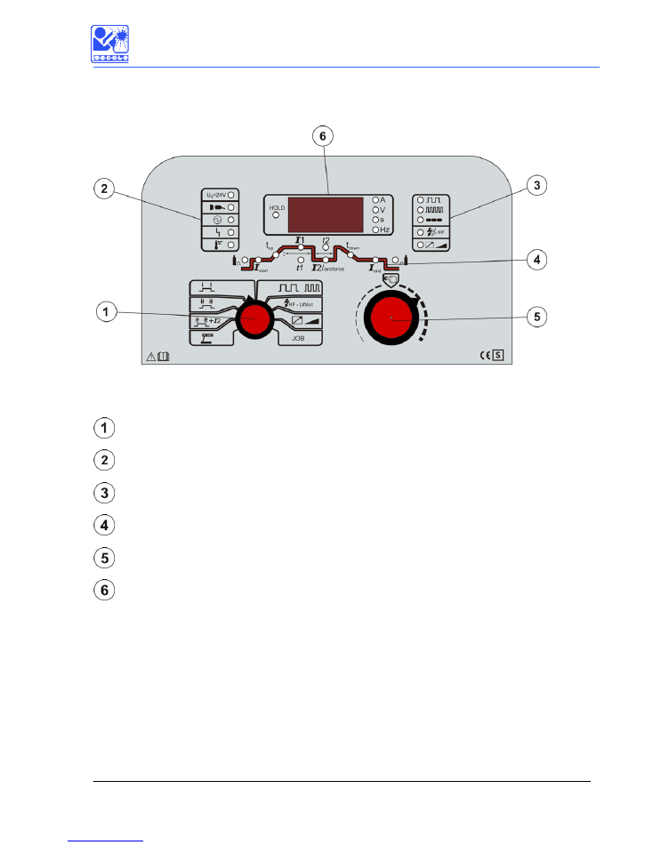
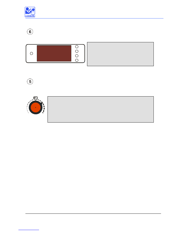
2. Control panel and display
6
1.1 Control panel and display
stepswitch for operation selection
status display
operation mode-display
programm-display
potentiometer with push-button
multifunctional-display
2. Control panel and display
7
Stepswitch for operation selection
With the stepswitch you can select the operation mode as well as additional functions:
TIG 2-stroke operation
TIG 4-stroke operation
TIG 4-stroke operation with 2nd current
Electrode hand welding
Slow pulse / fast pulse / spot welding operation
High frequency ignition /
LiftArc ignition
Energy adjustement with remote control / on the front panel
JOB
JOB-mode: Selection and editoring of welding jobs
Statusdisplay / Operation mode
„open voltage <24V“ for electrode welding is in use (optional)
Supply voltage present
Welding in use
Fault indicator: machine is not ready for use
overtemperatur : inverter overheated
Slow pulse activ
Fast pulse activ
Spot welding activ
TIG ignition with high frequency
Energy adjustment with remote control
Program flow display
2. Control panel and display
8
During the welding process it shows every step in the program flow that is currently in use.
When not in operation it shows which parameter can be adjusted with turning of the
potentiometer .
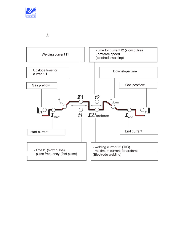
The following drawing explains the meaning of the symbols:
2. Control panel and display
9
Multifunctional-display
The multifunctional-display shows the welding parameters and machine setup.
HOLD
A
V
s
Hz
LED current in ampere
LED voltage
LED times in seconds
LED frequency in Hz or kHz
If the „HOLD“- display is lit, the last welded current is shown.
Potentiometer push-button
Parameter adjustement can be done by turning the potentiometer. Additionally by pressing the
potentiometer the following selections can be made:
push-button function
short pressing:
next step in the program flow will be shown on
the display
steady pressing:
Program flow will be shown until release of the
push-button.

Installation
10
Installation of the machine
Place the machine at least 0.80 m from a wall etc. to guarantee the cooling air can go through the
unit. The room temperature should not exceed 40°C.
Main supply voltage
The main supply must be connected by a trained person. The main supply voltage is displayed on a
sticker at the machine. The protection earth must be connected.
Earth lead (work cable) and stick electrode welding cable
The earth lead must have an excellent ground. The clamp should be atteched to a clean, paint
and rust free area on the workpiece or on the welding table.
Maintenance
The maintenance of the welding machine consists of a regular cleaning and inspection. It depends
on the enviroment of the working area and the working hours.
Operation at generators
The genarator must supply at least 10 % more power than the maximum power requirement of
the welding unit. For the operation of the MobiTIG 190 DC a minimum power of 6 kVA is required.
Switch on the welding unit after the generator has been switched on.
Operation outside the workshop
The unit can be placed and operated outside the workshop according to the protection class
IP 23. Make sure that all electrical parts are well protected against rain and water.

Installation
11
While in use for example after switching the operation mode, short messages will be shown in the
Display. Please find
there meaning in the below table:
display
2 t
2-stroke operation
4 t
4-stroke operation
4 t S
4-stroke with 2nd current
E L
Electrode welding
P u
Stepswitch for operation mode inposition
H F
Stepswitch for operation mode in position
HF - LiftArc
F r o
Energy control on the front panel
J o b
Job-mode in use
b t
Torch trigger is pressed

12
Current adjustment:
Please find here standard settings for the TIG manual welding in horizontal position of stainless
steel:
Mate-
rial-
thick-
nes in
mm
Weld
-form
Seam-
distance
in mm
Aprox.
welding-
current
in
A
Number
of layers
Welding-
rod
in mm
Tungsten
electrode
grey
in mm
Gas
nozzle
Argon
welding
gas
l/min.
0,6
I
-
20-30
1
1,6
1,0
4
5
0,8
I
-
40
1
1,6
1,0
4
5
1,0
I
-
45
1
1,6
1,0
4
5
1,5
I
-
50
1
1,6
1,6
4-6
6
2,0
I
-
80-100
1
2,4
1,6
6-8
7
2,5
I
-
100-130
1
2,4
1,6
6-8
7
3,0
I
-
140
two sided
2,4
2,4
8
7
4,0
I
V-
shaping.
180
1
2,4
3,2
8-10
10
6,0
I
V-
shaping.
220
2
2,4
3,2
8-10
10
8,0
I
X-
shaping.
280
2 (3)
3,2
3,2
8-10
10
13
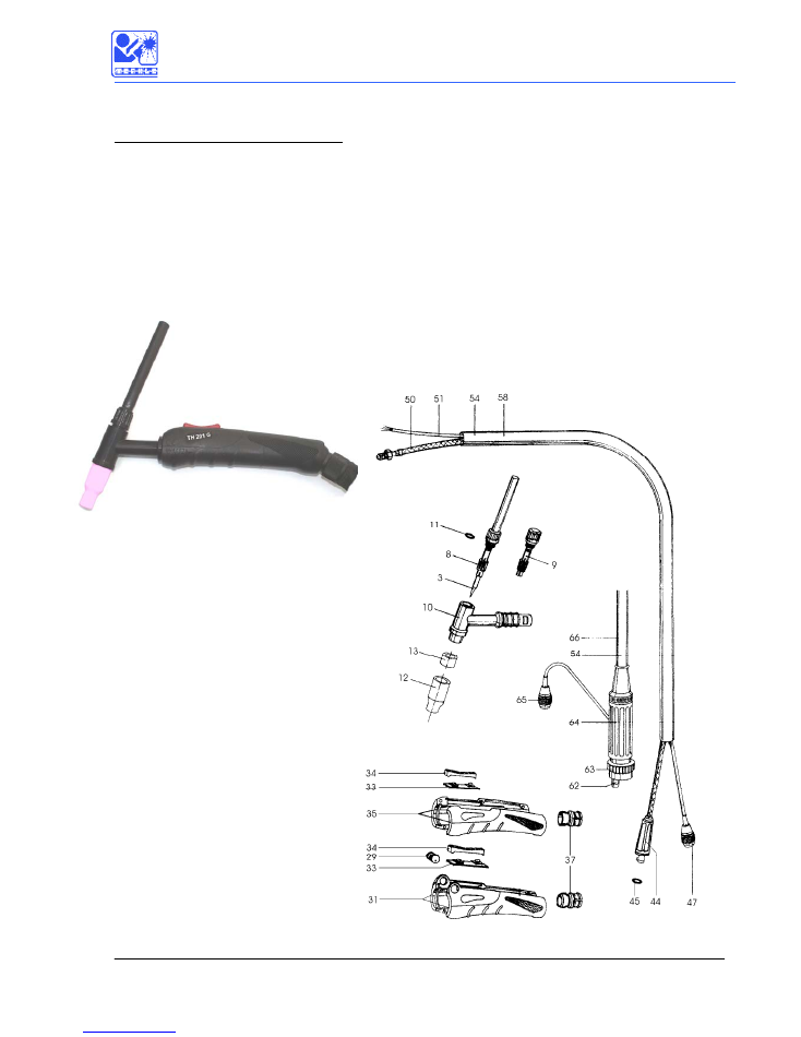
Spares and accessories
1.1 TIG-hand welding torch TH 201 G
Technical data:
Cooling:
gascooled
DC range:
200 A, 40 % ED
AC range:
180 A, 40 % ED (at 30 % positive polarity)
Tungsten electrodes:
1.0 – 2.4 mm
∅
Weight:
230
g
without
hose
assembly

14
TIG Hand Welding Torch, Model TH 201 G, gas cooled
Pos. Nr./no. Bezeichnung Description
Mit Merkle TCG-Anschluss: With Merkle TCG connector:
114.144 TIG-Handschweißbrenner TH 250 G, 4 m TIG hand welding torch TH 201 G, 4m
mit Merkle TCG-Anschluss, Leder/Textil with Merkle TCG connector,
mit Doppeldruckknopfschalter leather/fabric hose assembly
114.146 TIG-Handschweißbrenner TH 201 G, 8 m TIG hand welding torch TH 201 G, 8m
mit Merkle TCG-Anschluss, Leder/Textil with Merkle TCG connector,
mit Doppeldruckknopfschalter leather/fabric hose assembly
114.148 TIG-Handschweißbrenner TH 250 G, 8 m TIG hand welding torch TH 201 G, 8m
mit Merkle TCG-Anschluss, Leder/Textil with Merkle TCG connector
mit Schalter und Potentiometer and potentiometer,
leather/fabric hose assembly
Mit Euro-Zentralanschluss: With Euro Connector:
114.150 TIG-Handschweißbrenner TH 250 G-EURO, 4 TIG hand welding torch
mit Euro-Zentralanschluss, Leder/Textil model TH 201 G-EURO, 4 m
mit Doppeldruckknopfschalter with Euro connector,
leather/fabric hose assembly
114.152 TIG-Handschweißbrenner TH 201 G-EURO, 8m TIG hand welding torch
mit Euro-Zentralanschluss, Leder/Textil model TH 201 G-EURO, 8 m
mit Doppeldruckknopfschalter with Euro connector,
leather/fabric hose assembly
114.154 TIG-Handschweißbrenner TH 201 G-EURO, 8m TIG hand welding torch
mit Euro-Zentralanschluss, Leder/Textil model TH 201 G-EURO, 8 m
mit Schalter und Potentiometer with Euro connector & potentiometer
leather/fabric hose assembly
114.156 TIG-Handschweißbrenner TH 201 G-MAG, 8 m TIG hand welding torch
mit MIG/MAG Euro-Zentralanschluss model TH 201 G-MAG, 8 m
HighPULSE 330/PU 300 K, Leder/Textil with MIG/MAG Euro connector
for HighPULSE 330/PU 300 K
Erstausrüstung: 2,4 mm, Keramik LW 10 Standard equip.: 2.4 mm, ceramic 10
Ersatz- und Verschleißteile: Spare parts and consumables:
3.1 013.0.0111 Wolfram-Elektrode 1,0 x 175 mm grau Tungsten-electrode, grey
Ceroxyd 1.0 x 175 mm
3.2 013.0.0112 Wolfram-Elektrode 1,6 x 175 mm grau Tungsten-electrode, grey
Ceroxyd 1.6 x 175 mm
3.3 013.0.0113 Wolfram-Elektrode 2,4 x 175 mm grau Tungsten-electrode, grey
Ceroxyd 2.4 x 175 mm
8.1 114.184 Spannkappe "Quick TIG" 1,0 mm, lang Back cap "quick TIG" 1.0 mm, long
TH 161/201 G TH 161/201 G
8.2 114.186 Spannkappe "Quick TIG" 1,6 mm, lang Back cap "quick TIG" 1.6 mm, long
TH 161/201 G TH 161/201 G
8.3 114.188 Spannkappe "Quick TIG" 2,4 mm, lang Back cap "quick TIG" 2.4 mm, long
TH 161/201 G TH 161/201 G
9.1 114.190 Spannkappe "Quick TIG" 1,0 mm, kurz Back cap "quick TIG" 1.0 mm, short
TH 161/201 G TH 161/201 G
9.2 114.192 Spannkappe "Quick TIG" 1,6 mm, kurz Back cap "quick TIG" 1.6 mm, short
TH 161/201 G TH 161/201 G
9.3 114.194 Spannkappe "Quick TIG" 2,4 mm kurz Back cap "quick TIG" 2.4 mm, short
TH 161/201 G TH 161/201 G
10 114.196 Brennerkopf TH 161/201 G Torch neck TH 161/201 G
11 022.1.0704 O-Ring 9 x 1,5 (P 583) O ring 9 x 1.5
12.1 104.260 Keramik-Gasdüse 6,5 TH 161/201 G, Ceramic nozzle 6.5, TH 161/201 G,
TH 170/250 G und TH 450/451 W TH 170/250 G, TH 450/451 W
12.2 104.262 Keramik-Gasdüse 8,0 TH 161/201 G, Ceramic nozzle 8.0, TH 161/201 G,

15
TH 170/250 G und TH 450/451 W TH 170/250 G, TH 450/451 W
12.3 104.264 Keramik-Gasdüse 10,0 TH 161/201 G, Ceramic nozzle 10.0, TH 161/201 G,
TH 170/250 G und TH 450/451 W TH 170/250 G, TH 450/451 W
Pos. Nr./no. Bezeichnung Description
12.4 104.266 Keramik-Gasdüse 12,5 TH 161/201 G, Ceramic nozzle 12.5 TH 161/201 G,
TH 170/250 G und TH 450/451 W TH 170/250 G, TH 450/451 W
12.5 104.268 Keramik-Gasdüse 15,0 TH 250 G, TH 450 W Ceramic nozzle 15.0
TH 250 G und TH 450/451 W TH 250 G, TH 450/451 W
13 114.214 Gaslinse komplett Gas lense for
für TH 161/201 G, TH 451 W TH 161/201 G, TH 451 W
29 108.354 Regelrad komplett mit Potentiometer Adjustement wheel incl.
für TIG TH Brenner potentiometer for TH torch
31 108.368 Griffschalenpaar TIG-Brenner mit Poti Handle TIG torch, right and left
(geliefert ohne Kugelgelenk) side for torch with potentiometer
(delivered without ball joint)
33 107.992 Platine für TIG-Brenner mit und ohne pc board for TIG double button
Potentiometer (für Brenner mit Kugel- switch (for torch with ball joint)
gelenk)
34 107.994 Wipptaster rot für TIG-Brenner mit Switch button (red)
Kugelgelenk for TIG torch with ball joint
35 107.988 Griffschalenpaar TIG-Brenner, schwarz Handle TIG torch, right and left
(geliefert ohne Kugelgelenk) side (delivered without ball joint)
37 107.998 Kugelgelenk für TIG-Griffschale Kinking protection for TIG handle
wassergekühlt mit Überwurfmutter
groß, schwarz
44 109.554 Stecker für Merkle TCG-Anschluss Merkle TCG connector plug
(gasgekühlt) komplett mit Gummitülle (gas cooled) incl. rubber housing
und 2 O-Ringen and 2 o-rings
45 103.544 O-Ring 8 x 1,6 O-ring 8 x 1.6
47 021.1.0380 Brennerstecker 5-polig für Round plug 5-pole for TIG torch
TIG-Brenner (standard) (standard)
50.1 106.868 Gasstromkabel 4 m TH 201/250 G Power cable 4 m TH 201/250 G
für Einzel- u. TIG Euro-Zentralanschluss
50.2 106.872 Gasstromkabel 8 m TH 201/250 G Power cable 8 m TH 201/250 G
für Einzel- u. TIG Euro-Zentralanschluss
50.3 107.048 Gasstromkabel 8 m TH 201/250 G-MAG Power cable 8 m TH 201/250 G-MAG
für MAG Euro-Zentralanschluss
51.1 107.646 Steuerleitung 3 x 0,5 LIYY Control cable 3 x 0.5 LIYY
nicht abgeschirmt, farbig no shield
51.1 107.646 Steuerleitung 3 x 0,5 LIYY Control cable 3 x 0.5 LIYY
nicht abgeschirmt, farbig no shield
51.2 107.242 Steuerleitung 5 x 0,5 LIYY Control cable 5 x 0.5 LiYY
nicht abgeschirmt, farbig no shield
51.2 107.242 Steuerleitung 5 x 0,5 LIYY Control cable 5 x 0.5 LiYY
nicht abgeschirmt, farbig no shield
54.1 114.332 Überzugschlauch 4 m - Textil/ Leder Protection hose 4 m
für TIG Brenner leather/fabric for TIG torch
54.2 114.334 Überzugschlauch 8 m - Textil/ Leder Protection hose 8 m
für TIG Brenner leather/fabric for TIG torch
58.1 106.866 Schlauchpaket TH 201/250 G, 4 m Cable assembly 4 m, TH 201/250 G
Merkle TCG-Anschluss incl. Merkle TCG connector,
(Steuerleitung 3 x 0,5) control cable 3 x 0.5
58.2 106.870 Schlauchpaket TH 201/250 G, 8 m Cable assembly 8 m, TH 201/250 G
Merkle TCG-Anschluss incl. Merkle TCG connector,
(Steuerleitung 3 x 0,5) control cable 3 x 0.5
58.3 106.871 Schlauchpaket TH 201/250 G, 8 m Cable assembly 8 m, TH 201/250 G
Merkle TCG-Anschluss incl. Merkle TCG connector,
(Steuerleitung 5 x 1,5) control cable 5 x 1.5
Schlauchpaket mit Euro-Zentralanschluss: Cable assembly with Euro connector:
62.1 013.4.0048 Messingkörper Zentralanschluss TIG Brass body for TIG Euro connector
gasgekühlt mit 5/8"-UNF-Mutter incl. nut 5/8"
62.2 025.1.1401 Messingkörper Zentralanschluss MAG Brass body for MIG Euro connector
gasgekühlt incl. nut 5/8"
63 025.1.0300 Überwurfmutter schwarz Euro adapter nut

16
64.1 013.4.0049 Knickschutz maschinenseitig 3-teilig Kinking protection at machine side
für TIG-Euro-Zentralanschluss gasgekühlt TIG Euro connector (set 3 pieces)
(Gehäuse m. Bohrung, Mutter, TIG-Tülle)
64.2 025.1.1300 Knickschutz maschinenseitig 3-teil. Kinking protection at machine side
für MAG Euro-Zentralanschluss gasgekühlt MIG Euro connector (set 3 pieces)
(Gehäuse, Mutter, MAG-Tülle)
65 021.1.0380 Brennerstecker 5-polig für Round plug 5-pole for TIG torch
TIG-Brenner (standard) (standard)
66.1 108.504 Schlauchpaket TH 201/250 G-EURO, 4 m Cable assembly 4 m, TH 201/250 G
Euro-Zentralan. (Steuerleitung 3 x 1,5) incl. Euro connector,
Lederschlauch control cable 3 x 0.5
66.2 108.506 Schlauchpaket TH 201/250 G-EURO, 8 m Cable assembly 8 m, TH 201/250 G
Euro-Zentralan. (Steuerleitung 3 x 1,5) incl. Euro connector,
Lederschlauch control cable 3 x 0.5
66.3 108.507 Schlauchpaket TH 201/250 G-EURO, 8 m Cable assembly 8 m, TH 201/250 G
Euro-Zentralan. (Steuerleitung 5 x 1,5) for torch with potentiometer
für Brenner mit Potentiometer (Leder) incl. Euro connector,
control cable 5 x 0.5
66.4 107.047 Schlauchpaket 8 m kpl TH 250 G-MAG Cable assembly 8 m, TH 201/250 G-MAG
MAG-Zentralan. (Steuerleitung 3 x 0,5) incl. Euro connector,
control cable 3 x 0.5
Änderungen vorbehalten. Changes reserved.

17
2 Wire diagram
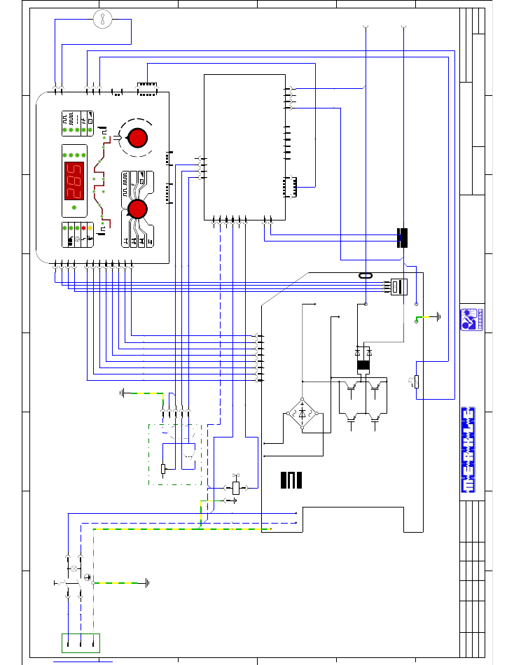
Projektnummer:
E
D
C
B
F
A
E
D
C
B
F
8
7
6
5
4
3
2
1
8
7
6
5
4
3
2
1
Bl.
Blatt
Norm
Gepr.
Bearb.
Datum
Name
Datum
Änderung
Zustand
Schweißanlagen-Technik GmbH
D-89359 Kötz
Industriestraße 3
Tel.: 08221-915-0
Fax.: 08221-915-40
www.merkle.de
1
Stromlaufplan
Stromquelle
MobiTIG 190DC
08.09.2009
Konrad Rudolf
9000768
1
Erdungsschraube
-L1
-X2
-
1
2
3
4
1
2
3
4
N
PE
L1
1
2
3
M
=
-M1
ME-BT-6.x
3
2
1
X5
230V-AC
2
1
X4
HF
HF
4
3
2
1
X6
BT2/Poti-Brenner
GND-Brenner
BT1-Brenner
4
230V-AC
5
Gasventil
6
4
3
2
1
X2
5
4
3
2
1
X1
-
+
1
20
X3
6
-A3
1
2
3
4
5
1
2
3
4
-X1
+
1
2
3
4
A
E
S
Schirm
1
1
1
2
1
2
3
4
5
6
7
8
ME-TIG-6.x
X5
4
3
5
4
7
6
8
2
1
2
1
3
1
2
1
2
3
X6
X4
X3
X7
20
1
X8
10
1
X2
6
1
X1
20
1
Uo>24
HF
A
V
s
Hz
Hold
I
Start
T
I1
t1
I2
t2
t
I
JOB
+15V
OutA
-24V
GND1
OutB
GND2
IPrA
GND
Iist
+15V
IPrB
-15V
NTC-IN
NTC-GND
OT-IN
Lüfter
GND
up
down
end
I2
HF-LiftArc
-A2
6
1
2
3
4
5
6
7
8
IN
-24V
GND1
+15V
OutB
OutA
GND2
IPrB
IPrA
2
3
4
1
DCM
DCP
Ferritring 3 Windungen
PE
+
-
Out+
Out-
AC1
AC2
AC3
AC4
ME-IC1-ELIN1.x
-A1
PE_2
1
2
3
4
5
6
7
8
1
-X3
2
3
4
5
-Q1
1
4
2
5
-Y1
Brenner
Werkstück
Netzanschluß
1PH-230V/50-60HZ/PE
Maschinengehäuse
Lüfter
blau
rot
Maschinenhaube
Gasventil
rot
weiß
gelb
grün
Befestigungsschraube
Fernreglersteckdose
1
2
3
4
5
Fußfernregler
BT
ws
bn
vio
rt
bl
-W1
bn
bl
gn/ge
gn
gr
gn-ge
sw
gn-ge
sw
sw
-W2
Flachbandkabel
ws
ws
ws
ws
ws
ws
ws
ws
gr
19
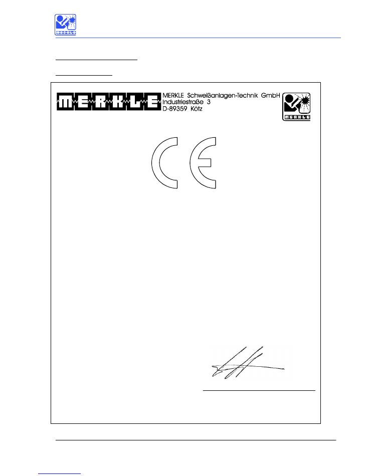
3 Conformity Attestation
3.1 MobiTIG 190 DC
EU
–
Conformity Attestation
Description of the unit:
TIG Welding Unit
Model:
MobiTIG
190
DC
The above mentionned unit complies with the following European Regulations:
EU-Low Voltage Regulation 73/23/EWG
EU-Electromagnetic Compatibility 89/336/EWG
In case of any modifications, incorrect repairs not exclusively authorized by Merkle, this attestation
looses its valdity.
Applied norms
EN 60974 - 1 / IEC 974 - 1 / VDE 0544 part 1
EN 60204 - 1 / IEC 204 - 1 / VDE 0113 part 1
EN 60974-10 / VDE 0544 Teil 10
K
ö
tz, September 21st, 2009
Wilhelm Merkle, Generalmanager
Merkle Schweissanlagen-Technik Gmb