Full Text Searchable PDF User Manual
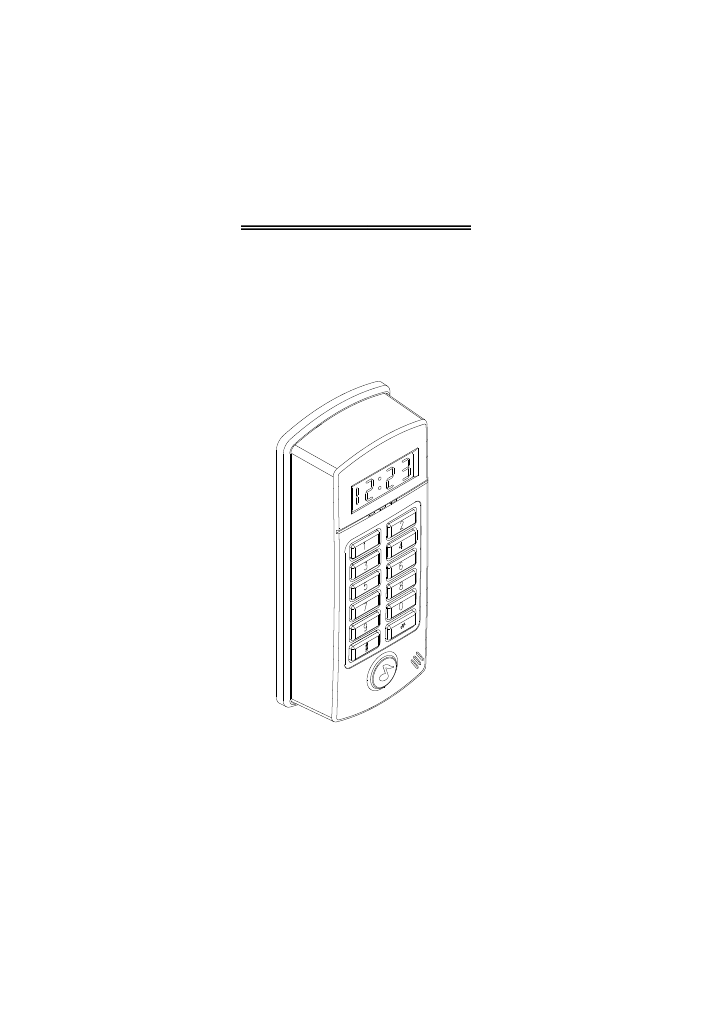
ST-780 Series
NETWORK PROXIMITY ACCESS CONTROL OPERATION
AND INSTALLATION MANUAL
VER 15.09.01

CONTENTS
ATTENTIONS
1. Features introductions
2. Installation procedures
3. Reader front panel & types of proximity card
4. Operation instructions
Start reader
Proximity
Anti-duress
Setup mode
5. Quick setting
6. Setting modes & functions
(01) Add New Card
(02) Delete Card
(04) Shunt Time
(05) Door Open Mode
(08) Change System Password
(10) Reader ID Number
(13) Total Cards
(15) Set Time
(16) Set Date
(18) Main Reader Location
(28) Display Card Number Mode
(00) Instant Door Open
(80) Communication Mode
(81) Wiegand Mode
(82) Card Number Door Open Mode
(83) Access Control Mode
7. Installation instructions
(1) Reader connector
(2) Wiring additional electric lock and push button
(3) Wiring for additional reed switch door sensing
(4) Wiring on for anti-duress alarm
(5) Wiring for alarm
(6) Wiring for linking with computer
(7) Additional door bell wiring
(8) Wiring for external subreader
(9) Example: Door Open point with external RELAY
8. Installation of the unit
9.Attentions
10.Troubleshooting
2
3
6
9
8
1
4
5
5
5
5
5
5
6
6
7
7
8
9
10
11
11
11
12
12
13
13
14
14
14
15
16
16
16
17
17
17
18
19
19
ATTENTIONS
1
+
Electric lock
Diode
500mA
Power supply
Electric Locks
+ External
Relay
AC 24V
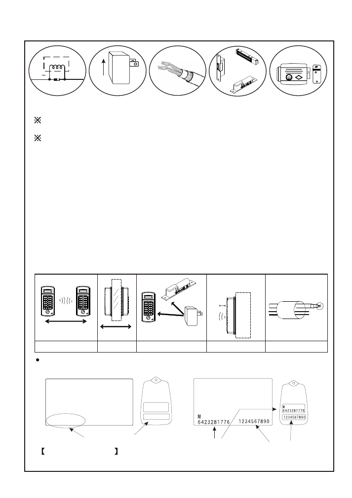
1.Power Supply requirement: DC 12V 500mA or above.
2.Door opening or alarm connector output: Maximum load of 1A@12VDC.
Connect with external RELAY to control higher voltage or current .
3.Electric Lock: Fail-safe or Fail-secure type (Refer to p13).
Please note: In order to protect the proximity unit, please connect one Diode
between two power supply connectors of electric lock to absorb surge.
4.Please use 24AWG and above of double shieled twisted pair wire for communication
wires.
5.Avoid installing the unit at the following environment:
A. Machines with the same frequency as the proximity unit around the neighborhood.
B. In the area of a base station with radio or wireless transmission.
C. On metal wall (proximity distance will be shorten).
6.It is suggested to separate the power supply of electric lock and proximity unit in order
to stabilize the power supply.
7.It is IP54 waterproof and its surface is completely waterproof. Please apply waterproof
silicone on its base if it is mounted on rough surface to make sure its base is waterproof.
8.Do not place communication and power supply wires at the same route in order to
prevent interference which might cause abnormal communication.
9.Communication methods: Use of RS-485, TCP/IP, USB interfaces to connect
with computer.
Too close
Too close
Sharing the same
power supply
Proximity distance
becomes short
Metal
1234567890
1234567890
18838:00722
Card number in the back of the card
Example of the card
The last 8-digit number of 1234567890 is 34567890.
125KHz(EM)
Card number
Chip serial number
(non-serial)
Card number
(serial)
13.56MHz(MIFARE)
X
X
X
DC 12V
X
X
AC
24AWG
Wires
Communication wire
DC 12V

1.Features introductions
2
Multiple waterproof design with built-in door bell button. It is suitable for both indoor
or outdoor use.
LED indicator to display time and card number. It displays setting modes when it is
used for standalone setting.
Frequency:125KHz or 13.56MHz
Proximity range: 1.5-7cm according to the types of card and frequency use.
Dimensions: 140L X 60W X 30H(mm)
Power supply : DC12V, Power consumption: 110mA (standby); 150mA (operation).
0-70 ,
85%Rh
Max.
When connecting with computer, it can be used for data inquiry and function setting
simultaneously. (Door open/close, activate alarm system, etc). It can also operate
solely to manage access control.
Function setting can be done by computer or reader itself. (Single registration or
deletion, door open time, etc).
The historical data can reach up to 9,000 by single reader operation. When linking
with computer, its data input/output capacity is unlimited.
Main reader has 4,500 card registrations capability. Each card is able to do self-setting
for personal password and effective in/out time.
Main reader has 48 units of time zone. Each time zone unit also has 5 time ranges for
user to set.
Example: It can be set from"G" hour "H" minute to "I" hour "J" minute on Mondays,
Wednesdays, Saturdays in periodical of "A" year "B" month "C" day to
"D" year "E" month "F" day as effective in/out time range.
Equipped with hardware self-testing function.
Internal batteries will provide power supply when power cut occurred to prevent any
data from being erased and system time can operate as normal.
Main reader access control's range:
Card number - It must be registered before use.
Password - Personal password has to key in to open the door.
Time zone - Setting the effective year, month, day, time range, Monday-Sunday.
Special holidays- User could set any holidays as to prevent any unauthorized access.
Error control - Alarm will activate when"N" times of consecutive error password
entering occurred.
Main reader's sensing range:
Anti-tamper - When the reader is tampered , alarm will be activated.
Anti-duress - It will operate when password and duress code are entered to send help
signal to the nearest police station. It must be done manually to disable anti-duress
function.
Door open button sensing - Door will open immediately when the button is pushed.
Anti-theft - Alarm will be activated when sensing any abnormal operations.
Exceed door shut time - Alarm will be activated, when door is not closed exceeding
initial time setting control.
External sub-reader available to connect.
Operation temperature :
Humidity:
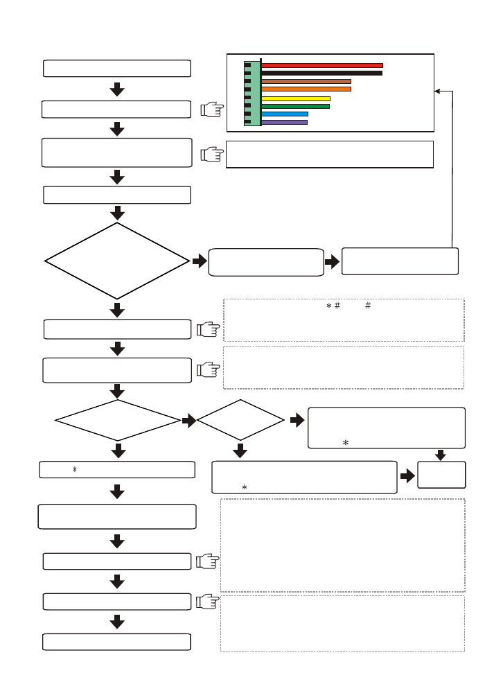
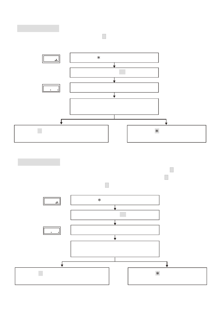
2.Installation procedures
Mount the unit (Page 17)
Wiring (Page 13-1 6)
Power supply to the reader
Enter setting mode
Adding new cards(standalone)(Page 6)
If not, disconnect the
power supply immediately.
Ensure the adapter's voltage
and polarity are correct.
R
BK
BR
O
Y
G
BL
P
12VDC
GND
Enter system password (
5678
), then a beep sound
and yellow indicator light to enter into setting mode.
If there isn't any activation, this system will automatically
escape from the setting mode.
Door open Relay output jump
(Page 13)
Door Open Relay output as N.O.(default)
Default reader number is 001. Enter 10 and then 3-digit
reader number to change reader number(each reader
has its own reader number for software to recognise ).
Operation with
computer online
Standalone
mode
Deleting cards
(standalone)
(Page 6)
Enter 01 and proximity card or enter
card number. One beep sound to
complete registration.
Press
button to escape.
Enter 02 and proximity card or enter card number.
One beep sound to complete deletion.
Press
button to escape.
Completion of setting
3
NO
NO
YES
YES
Check if power
(RED)indicator is on.
Then, the screen will
show time
Completion
of setting
Press
button to exit setting mode
Activate the software
(default account:USER,password:0000)
Add new user and reader
Send all settings to the reader
Send all data to the reader when all settings are
completed in order to operate.
Data which need to be sent are:1. Time 2. User's data
3. Time Zone 4. Parameter
Please refer to the software manual for detailed operation.
1.Default reader number is 1 and communication interface is
Com1 when entering into the software.
2.Reader number 1 will respond when both interface and time
are correct. Please check the wiring and its interface and
reader number when there is no response from the reader.
3.Click Basic Information setting ->User->Add new user
Information / Data.
4.Click Basic Information Setting ->Reader->Add New Reader.
Reader number or change reader
number(
Page 8
)
Wiring
Communication
Door open RELAY
Wiegand input
3.
Reader front panel & types of proximity card
4
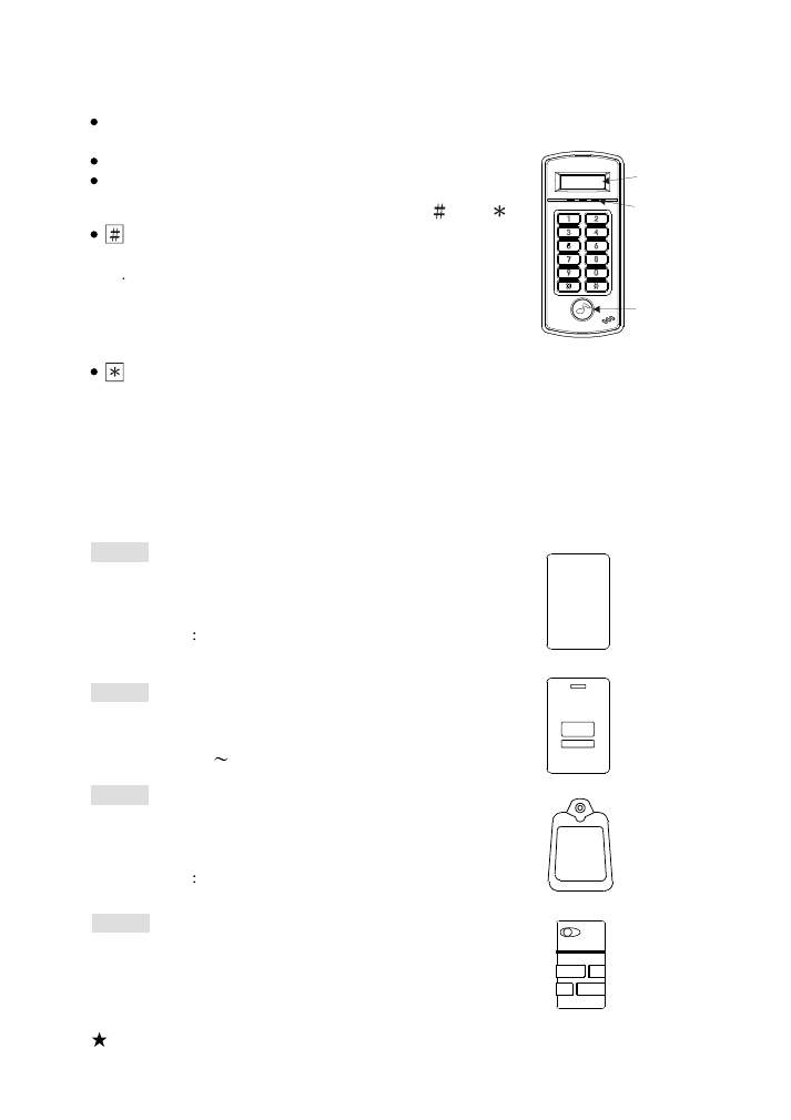
(1) Front Panel Indicator Lights
POWER (Red) : Power indicator(On).
Operation error (Flashing).
OK (Green) : Door open indicator.
STATUS (Yellow) : Enter system setting mode.
(2) 10 entry (button), two function keys : "
" & "
".
key:
A. Enter data confirmation button (ENTER)
B Card number will be displayed on the screen when
the card is proximity and # button is pressed.
(The function is available when "Display Card Number
Door Open Mode" function is set as ON;
please refer to P9 for setting Function 28).
key: clear or escape button (CLR/ESC)
Display Screen
LED Lights
Door Bell
Push Button
(4) Types of proximity card
SC-30
Key tag, dimensions: 51L X 32W X 7.8H (mm).
Ultrasonic connection, waterproof,
shock- proof. Read range :
EM 125KHz
2-3.5cm
Mifare 13.56MHz:1.5-2.5cm
12345678
SC-20
Thick card, thickness of 1.78 mm, ISO standard
card dimensions. Read range :
EM 125KHz : 5
7cm
12345678
SC-10
Thin card, thickness of 0.8 mm, ISO standard
card dimensions. It can be printed directly
from card printer. Read range :
EM 125KHz
5- 7cm
Mifare 13.56MHz:3-5cm
SC-50
Key tag, dimensions: 46L X 25W X 7H (mm).
Ultrasonic connection, waterproof,
shock- proof. Read range :
Mifare 13.56MHz:1.5-2.5cm
ST-780 :125KHz EM-Marin format
ST-780MF:13.56MHz Mifare SOCA format
ST-780MH:13.56MHz Mifare SOCA V.2 format
ST-780M :13.56MHz Mifare format
(3) Model series
The above read range stated is for reference and it is varied according to
the different environment it is used.
4.Operation instructions
Start reader
It begins self-testing function when power is on. Display current time
on the screen when it is completed.
Proximity :
Sense the card near the unit. The following states are shown below.
A. Green light (OK) is on to display card number and open the door.
It is a valid card.
B. Continuous beep sound (DENY). It shows invalid or unregistered card or invalid
time or under access control.
Anti-duress
When under duress, presses
button before entering password
to activate alarm. (Default value of duress code is
, it can be changed by user)
Example : Anti-duress code is 1, password is
1 2 3 4. In order to activate anti-duress
alarm, user should key in
1 2 3 4
.
Note:This function is only available for Door Open Mode 3-proximity and password mode.
5
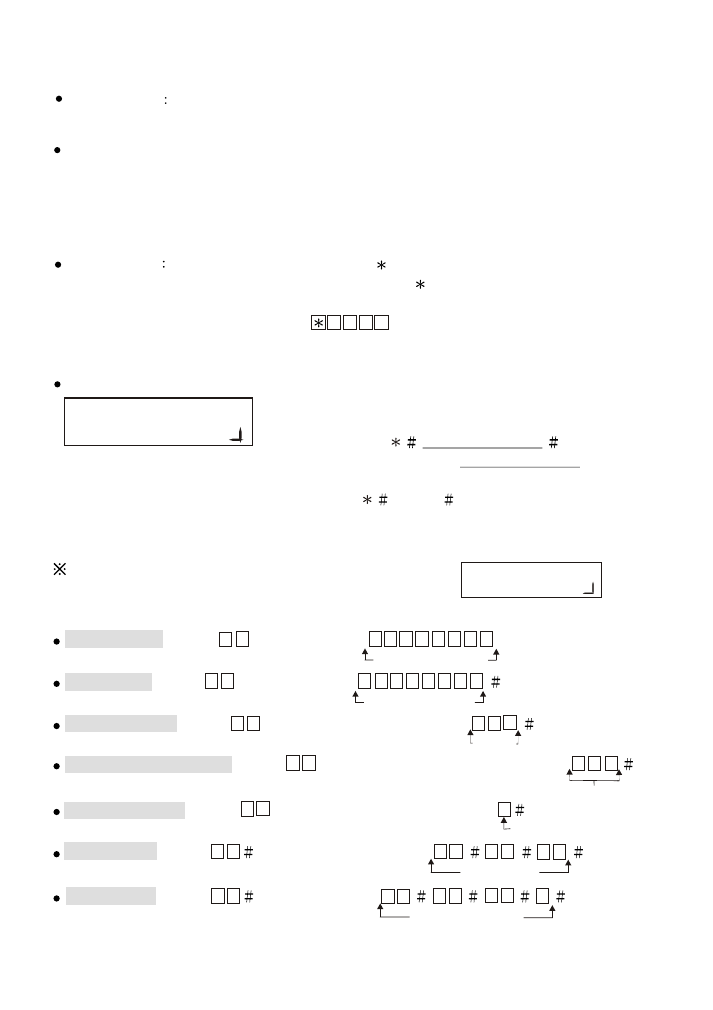
Setup mode:
User must enter into setting mode first before changing
any system functions.
User must enter
system password
for system
function selection. Default system password as 5 6 7 8 .
(Example: User can enter into the set up mode
by entering
5 6 7 8
).
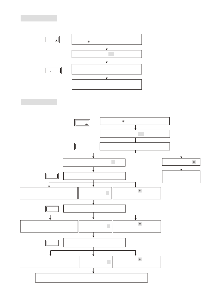
Add new card , enter
0 1
and then enter
0 0 0 0 0 0 0 1
or proximity card.
8-digit card number
Delete card , enter
0 2
and then enter
0 0 0 0 0 0 0 1
8-digit card number
Door open time , enter
0 4
and then enter the seconds
0 0 3
Seconds
Change reader number , enter
1 0
and then enter the reader number
0 0 2
Door open mode , enter
0 5
and then enter the mode code
2
Door open mode
Time setting , enter
1 5
and then enter the time
1 3
0 0
1 5
13:00:15
Date setting , enter
1 6
and then enter
0 0
0 1
0 1
6
2000/01/01 (6)
5.Quick setting
User must enter into the setup mode as the right diagram
shown for any settings to be set.
.
Reader number
..
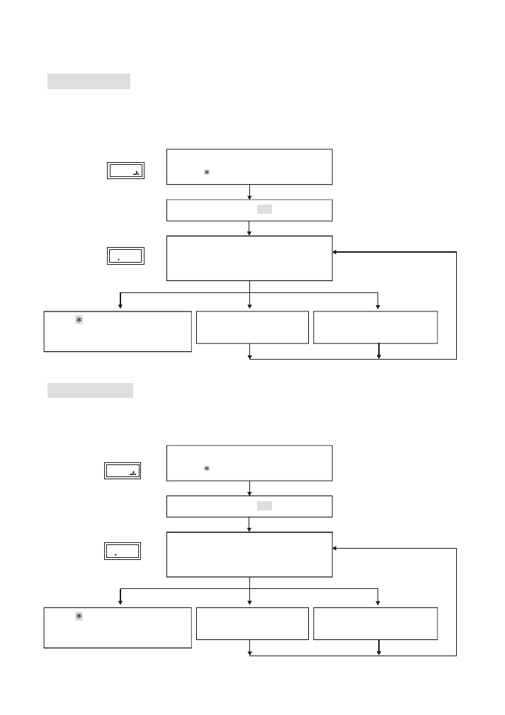
6.
Setting modes & functions
Function
(01)
Add New Card
6
Either enter 8-digit card number or use proximity card to register, both can be accepted
but should be registered prior use.
Function (02)
Delete Card
Deletion of user's card (such as loss of card or to prevent specific user to gain access)
can be achieved by entering 8-digit card number indicated on the proximity card.
Enter
1 #
Proximity card or
enter 8-digit card number
and press # manually
Proximity card or
enter 8-digit card number
and press # manually
Registration completed,
one beep sound.
Repeated registration,
continuous beep sound.
Enter
# system password #
Display
Display
2
Display
Display
1
Enter
to clear.
It goes back to system function
selection when nothing is entered.
Enter 2
#
Deletion
completed,
one beep sound.
Error.
Continuous beep sound.
Enter
# system password #
Enter
to clear.
It goes back to system function
selection when nothing is entered.
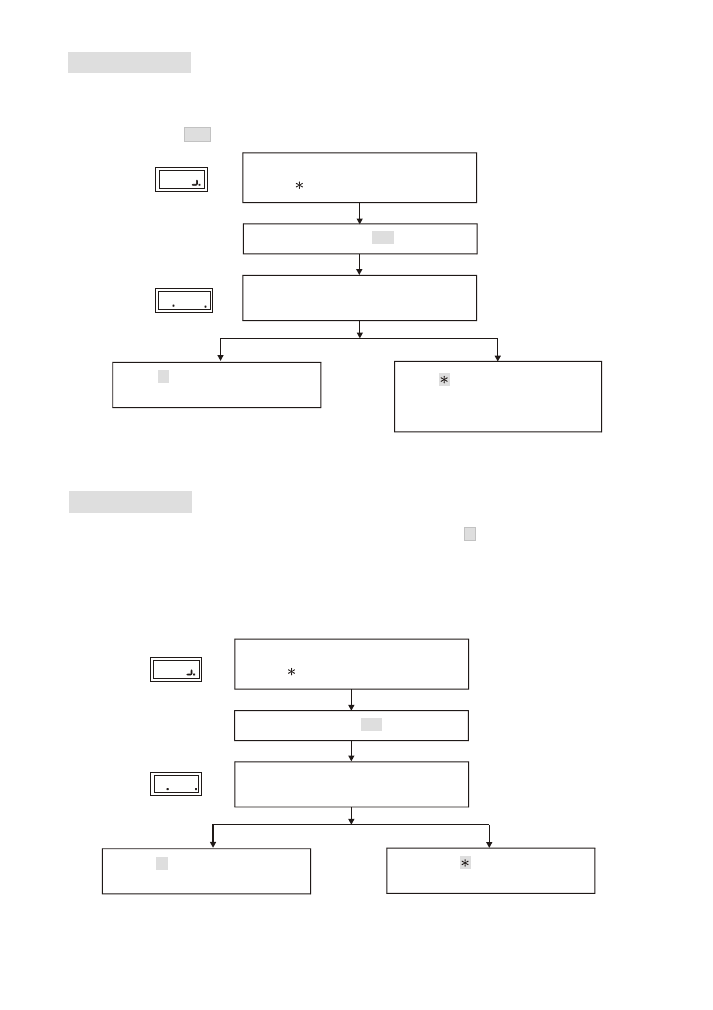
Function (04)
Shunt Time
Setting of relay's ON/OFF time in the proximity reader can be set from 0-255 seconds.
Set 000 as toggle function as the door is always open until the next proximity.
(default value as 003 )
Function (05)
Door Open Mode
Reader has 2 types of identification modes. (default value as 2 )
Mode (2). Card proximity door open: The
door opens, when the card is sensed.
Mode (3).
Door open by proximity card and password: The door opens by entering
additional 4-digit password after sensing the
registered card.
Enter shunt time(0-255)
Enter
# system password #
Enter # to go
Enter # to go
back to system function selection.
back to system function selection.
Enter
to clear.
It goes back to system function
selection when nothing is entered.
Enter
to goes back to
system function.
Enter door open mode(2 or 3)
Enter
# system password #
Enter
4 #
Enter
5 #
4 00
5
2
Display
Display
Display
Display
7
Function (08)
Change System Password
Default system password as
5 6 7 8
.
In order to enter into system setting mode for the first time, user must enter the default
system password
5 6 7 8
. User may change the system password after entering into
system setting mode.(4-6-digit password to set)
Function (10)
Reader ID Number
Each reader has a reader ID number for computer identification and the number should not be
repeated. Setting range 1-255, default value as 001.
8
Enter
8 #
Enter
# system password #
Nothing is entered
Enter
Back to system function selection.
Enter new system password (4-6 digits)
Press # button after entering.
Nothing is entered
Enter
Enter 1-255
and then
#
button.
Enter 10
#
Back to system function selection.
Enter
# system password #
8
Display
Display
10
0
Display
Display
Setting completed,
one beep sound.
Error.
Continuous beep sound.
Setting completed,
one beep sound.
Error.
Continuous beep sound.
back to system function selection.
Press any key to go
Function (13)
Total Cards
Display total number of current registered cards.
Display total number of
current registered cards.
Enter 13
Enter
# system password #
Display
Display
13
00
9
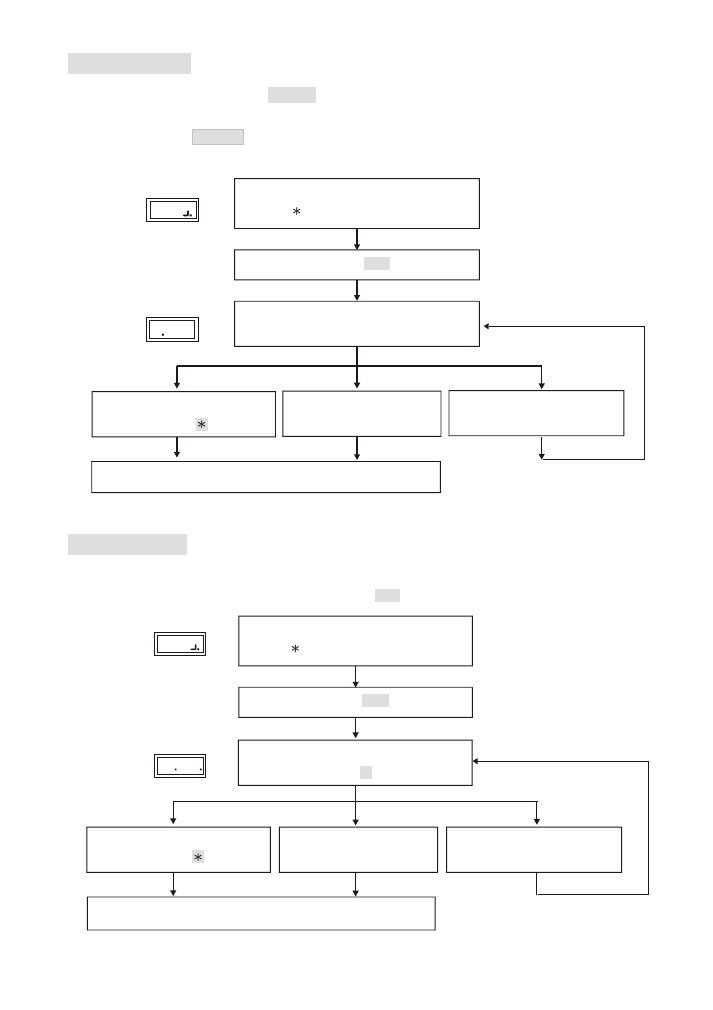
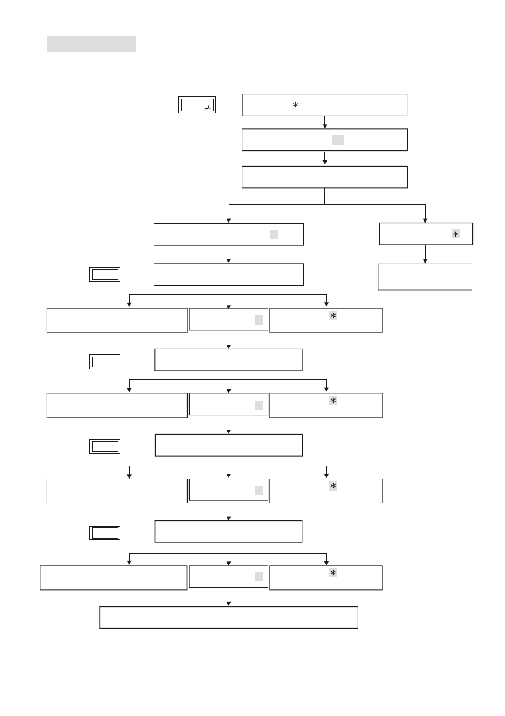
Function (15)
Set Time
Example: 18 hour 00 minute 00 second => 18:00:00 (
default value as
00:00:00)
Enter 15
Back to system
function selection.
Display
Display
Display
Display
Enter
# system password #
Change setting, enter #
Escape. Enter
Escape. Enter
to go back
to system function selection.
Escape. Enter
to go back
to system function selection.
Escape. Enter
to go back
to system function selection.
Display current time
Display
00:00
Enter hour (00-23)
Enter minute (00-59)
Enter seconds (00-59)
Confirm Enter #
Confirm Enter #
Confirm Enter #
Error. Continuous beep sound
and go back to hour entering.
Error. Continuous beep sound
and go back to minute entering.
Error. Continuous beep sound
and go back to seconds entering.
15.
2
1.
15.
3
15.
15.
1
One beep sound to go back to system function selection.
10
Enter 16
Back to system
function selection.
Display
Enter
# system password #
Escape, enter
Display current date
2007.01.01 1
Y
M
D
W
Function (16)
Set Date
Example 2012/04/30 Monday => 2012/04/30 (1) (
default value as
2007/01/01 (1))
Error. Continuous beep sound
and go back to year entering.
Error. Continuous beep sound
and go back to month entering.
Error. Continuous beep sound
and go back to date entering.
Error. Continuous beep sound and
go back to day of the week entering.
Confirm Enter #
Confirm Enter #
Confirm Enter #
Confirm Enter #
Change setting,enter #
Enter year (00-99)
Enter month(01-12)
Enter date(01-31)
Enter Day of the week (1-7)
One beep sound to go back to system function selection.
Display
16.
1
Display
16.
2
Display
16.
3
Display
16.
4
Escape. Enter
to go back
to system function selection.
Escape. Enter
to go back
to system function selection.
Escape. Enter
to go back
to system function selection.
Escape. Enter
to go back
to system function selection.
Enter
to goes back to
system function.
Enter
to goes back to
system function.
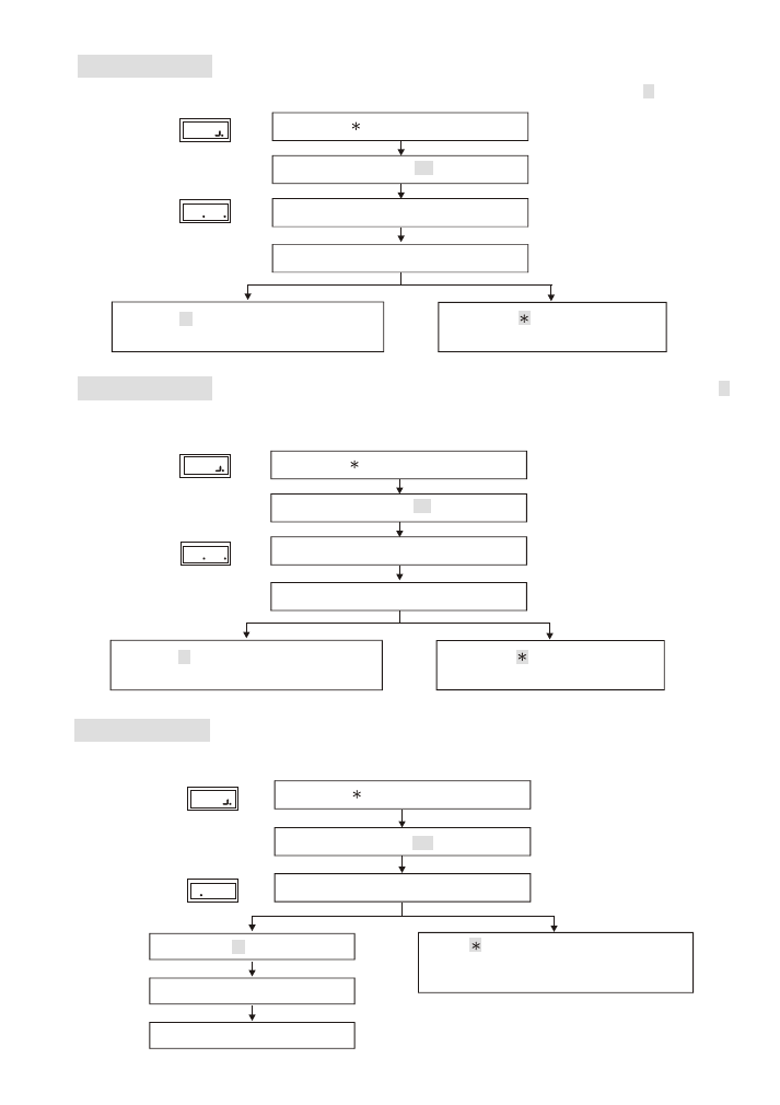
Function (18)
Main Reader Location
Function (28)
To show the location of the reader: (0) Indoor, (1) Outdoor. (
default value as
1 )
Enter 18
Enter main reader location code. (0 or 1)
0
Display
18 1
Display
Display
28 0
Display
Display
Display
Enter
# system password #
Enter # to confirm
Back to system function selection.
Display Card Number Mode:
(0)ON,(1)OFF. (default value as 0)
Card number is not displayed on the screen when it is set as OFF.
Enter
# system password #
Function (00)
Instant Door Open
Authorized personnel could get into the setup mode to open the door for emergencies.
Enter
or any key to clear.
It goes back to system function selection
when nothing is entered.
Enter 00
Open door
Back to the display screen
11
Display location code
Enter 28
Enter Display Card Number Mode (0 or 1)
Enter
# system password #
Enter # to confirm
Back to system function selection.
Enter # to confirm
Display Card Number Mode
Display System Door Open
Function (80)
(1)N.8.1 , (2) N.8.2 .
efault value as 2 .
Communication Mode
D
Function (81)
(0)
, (1)
.
Default value as 1 .
Wiegand Mode
Wiegand 26bit
Wiegand 34bit
Display
Display
80 2
Enter Communication mode(1 or 2)
Enter 80
Enter
# system password #
Enter # to confirm
Back to system function selection.
Display Communication Modes Setting
Enter
to goes back to
system function.
Display
81 1
Display
Enter Wiegand mode(0 or 1)
Enter 81
Enter
# system password #
Enter # to confirm
Back to system function selection.
Display Wiegand Mode
Enter
to goes back to
system function.
12
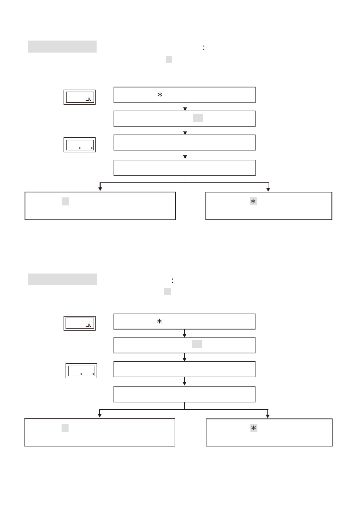
Function (82)
Card Number Door Open Mode
:
(0)ON, (1)OFF.
(default value as 1 ) Enter registered card's 8-digit card
number to open door when the function is set as ON.
Enter 82
Enter
# system password #
Enter # to confirm
Back to system function selection.
Display Card Number Door Open Mode
82 1
Display
Display
Enter Card Number Door Open Mode
(0 or 1)
Enter
to goes back to
system function.
Function (83)
Access Control Mode
: All access for all card holders
including unregistered card when it is set as 0 . Only valid or
registered card to access when it is set as 1 .
(Default value as 1 )
Enter 83
Enter
# system password #
Enter # to confirm
Back to system function selection.
Access Control Mode
83 1
Display
Display
Enter Code of Access Control Mode
(0 or 1)
Enter
to goes back to
system function.
13
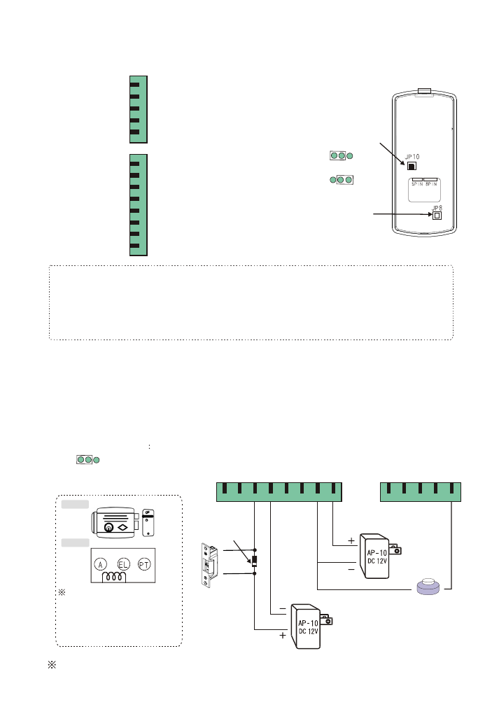
7.Installation instructions
(1) Reader connector
A. N.O.Connector (please use jump to adjust)
Suitable for : Fail-secure electric lock or electric lock requires N.O. point to trigger.
14
Jump Adjustment
JP10
N.O Output
(2)
Wiring additional electric lock and push button
As of different types of electric lock, the wiring methods are also different .
Overall, there are two types of wiring instructions as below:
Purple
Blue
Green
Yellow
Orange
Brown
Black
Red
Wiegand input (1)
Wiegand input (0)
Door open relay (N.O or N.C) terminal
Door open relay (Common) terminal
Signal (data-) receiver
Signal (data+) transmitter
Input power,negative GND
Input power,positive 12V
8-PIN
CONNECTOR
Purple
Blue
Green
Brown
Red
5-PIN
CONNECTOR
Push button door open point
Alarm output
Anti-duress output terminal
Door sensing input
Door Bell Button Output
Back
Anti-tamper
Switch
Note
:
(1)Current for Door Open RELAY point is 1A/12VDC.
Please connect to a relay if a device with 24 VDC or current is exceeding.
(Please refer to p16 for wiring)
(2)The current for Anti-tamper switch is 0.1A/12VDC.
Push button
Strike lock
Rim lock
The current of rim lock is
larger than 1A (please refer to
External RELAY is used
and both points of A. EL of
the electric lock.
p16)
Door Open Relay as dry contact with maximum load of 1A@12VDC.
Diode's white
color terminal
Bla R
Br
O
Y
G
Blu
P
5-PIN
8-PIN
P Blu G Br R
Internal
External
Door Open
Output JUMPER
N.O Output
N.C Output
15
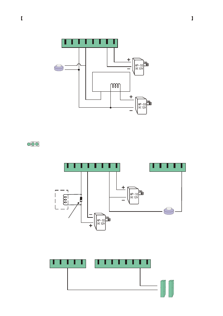
Example:
Micro-computer Fail-safe electric lock (use of N.O point to trigger).
B. "N.C" Connector(Please use jump to adjust)
Suitable for: Fail-safe electric lock such as electromagnetic lock.
(3) Wiring for additional reed switch door sensing
N.C Output
Jump Adjustment (Jp10)
Dead bolt lock
or Electro- Magnetic lock
N.O. type
reed switch
Push button
Microcontroller lock
8-PIN
P
S
Bla R
Br
O
Y
G
Blu
P
Push button
Diode's white
color terminal
Bla R
Br
O
Y
G
Blu
P
5-PIN
8-PIN
P Blu G Br R
5-PIN
P Blu G Br R
Bla R
Br
O
Y
G
Blu
P
8-PIN
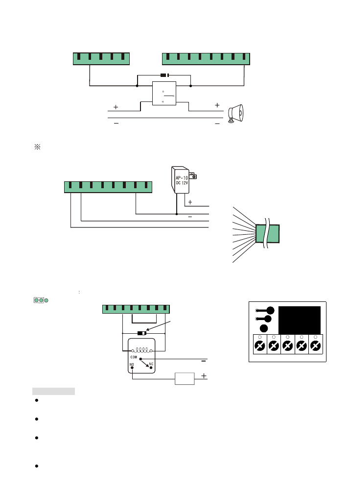
(4)
Wiring for anti-duress alarm
16
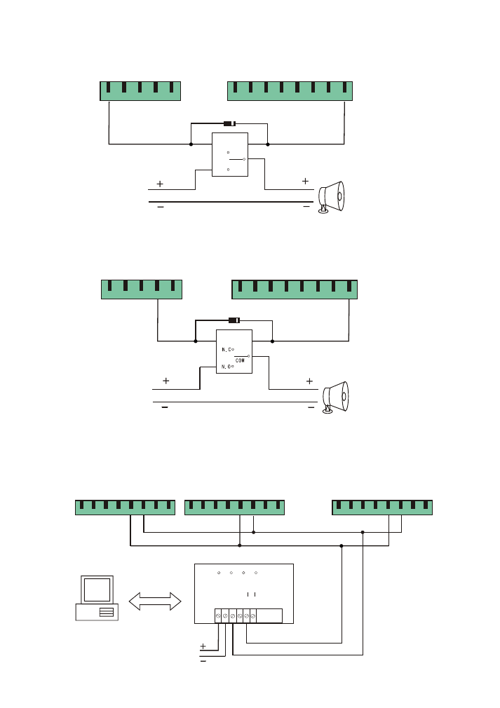
(6)
linking with computer
Wiring for
AP30 CONVERTER
RS-232 to RS-485
RS-232
V
C
C
G
N
D
D
T
+
D
T
+
D
T
D
T
DC12V
POWER TXD
RXD
(5)
Wiring for alarm
COIL
DC12V
COIL
N.C
COM
N.O
DC12V
RS-485 interface transit connector
Door bell
Door bell
Device 1
Device 2
Device N
Diode's white color terminal
Diode's white color terminal
5-PIN
P Blu G Br R
5-PIN
P Blu G Br R
Bla R
Br
O
Y
G
Blu
P
8-PIN
Bla R
Br
O
Y
G
Blu
P
8-PIN
Bla R
Br
O
Y
G
Blu
P
8-PIN
Bla R
Br
O
Y
G
Blu
P
8-PIN
Bla R
Br
O
Y
G
Blu
P
8-PIN
PC
RS-232
communication line
Bla R
Br
O
Y
G
Blu
P
8-PIN
(7)
(
)
Additional door bell wiring
External Relay is required
Red
Black
Gray
Purple
Green
Yellow
White
Blue
Orange
17
Door bell
Diode's white color terminal
5-PIN
P Blu G Br R
Bla R
Br
O
Y
G
Blu
P
8-PIN
COIL
N.C
COM
N.O
DC12V
Bla R
Br
O
Y
G
Blu
P
8-PIN
Subreader
(8) Wiring for external subreader
Suggested maximum length between the reader and the subreader as 50m and
24 AWG twisted pair wire is used.
Load
External power
(Voltage > DC12V or Current > 1A)
(9)
RELAY
Example: Door Open point with external
CNT+ CNT- N.C COM. N.O
CNT-
CNT+
AP-51(Optional)
Precautions
Maximun load of the door open RELAY as DC 12V / 1A . Please connect an external RELAY for
high voltage or current to prevent any damage to the internal parts(optional of AP-51 is available).
Examples of the wiring in this manual are for reference. Please refer to the electric lock's
manual for the actual wiring.
If the loading of the door open RELAY is not being used by an electric lock but for lift,
automatic door, please make sure its voltage loading range. If user is unable to specify its range,
it is suggested to connect an external RELAY.
Please connect a Diode for the external RELAY to absorb surge (please make sure its direction).
Diode's white color terminal
Jump Adjustment
JP10
N.O Output
18
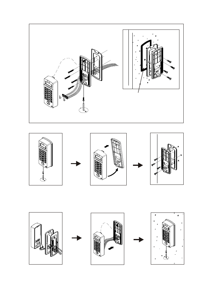
8. Installation of the unit
Step1:
Step4:
Use attached screwdriver
to unscrew the screws.
Separate the panel base
from the unit.
Screw the panel base and
waterproof rubber cushion
tight on the wall.
Place the wires through the
waterproof rubber cushion and
panel base in order. Connect
the wires with the unit.
Push the remaining wires in
the case and place both panel
base and the unit back together.
Use attached screwdriver
to tighten the screws.
Please apply waterproof silicone between
the mounted wall and rubber cushion on
rough wall to prevent water leakage to the
wiring hole in the back.

19
9.Attentions
(1) Confirm the power supply voltage and polarity before installation to prevent any wrong
connection that may cause damage to the reader.
(2) Use separate power supply to the electric lock and the proximity reader.
(3) Do not install the reader near any metal equiments or detector area to prevent
interference of read distance.
(4) Do not try to fix or modify the reader without authorized electrician.
The reader is guaranteed for one year.
(1) Reader has no reaction or door does not open with proximity card.
Solution:
(A) Please check if the red light is on. If not, please check the power supply to
turn the reader on.
(B) Please check if the proximity card is defected. User may use another proximity card
to test.
(C) Please check if personal password is entered incorrectly or the user is still in the
setup mode.
(D) Continuous proximity. Please remove the card from the reader and try again.
(E) Check if the yellow light is on and continuous beep sound occurred.
This indicates the user's proximity card is not registered yet.
(F) Please check if green light is on and door-opening sound can be heard at the
same time. If door is still not opened, please ensure that if the wiring or power supply
of electric lock is installed properly or broken.
(2) System password is entered but user cannot enter into various function selection of
the setting mode.
Solution:
(A) System password is entered incorrectly. Please check if the following step has been
entered correctly. # XXXX # .(XXXX represent system password),or press
button
first and then enter the correct system password # 5678 # .
(B) Bad wiring arrangement may affect key enter data.
Please confirm that the power supply wire and the control wire have been arranged to
the space at the back of the LCD (this is the wiring arrangement area of this unit).
This is to prevent the wires pressing on the wiring on the PC board causing bad
contact, short circuit and interference.
10.Troubleshooting