Full Text Searchable PDF User Manual
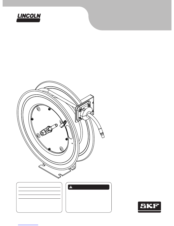
Air and water reels
Models 83753 and 83754
Series B
Installation and maintenance guide
Read manual prior to installation or use
of this product. Keep manual nearby for
future reference. Failure to follow
instructions and safety precautions may
result in death or serious injury.
D A N G E R
Date of issue
June 2014
Form number
404665A
Section
E35
Page
83A
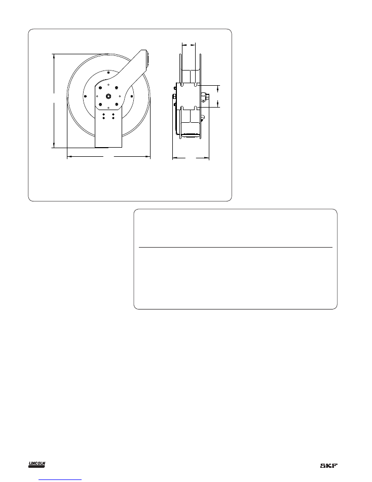
Dimensions
A
20.51 in.
(520,9 mm)
B 19.30 in.
(490.2 mm)
C
4.72 in.
(119,8 mm)
D 2.99 in.
(75,9 mm)
E
8.13 in.
(206,5 mm)
Safety
Personal injury and/or equipment damage
may result if proper safety precautions are
not observed.
• Ensure that reel is properly installed
before connecting input and output
hoses.
• Bleed air/water pressure from system
before servicing reel.
• Before connecting reel to supply line,
ensure that pressure does not exceed
maximum working pressure rating of reel.
• Remember, even low pressure is very
dangerous and can cause personal injury
or death.
• Be aware of machinery and personnel in
work area.
• If a leak occurs in the hose or reel, remove
system pressure immediately.
• A high tension spring assembly is con-
tained within the reel. Exercise extreme
caution.
• Pull hose from reel by grasping the hose
itself, not the control valve.
• Ensure that reel, hose, and equipment
being serviced are properly grounded.
• Use an ohmmeter to check ground
continuity.
• If reel ceases to unwind or rewind,
remove system pressure immediately.
Do not pull or jerk on hose! Treat the hose
reel as any other piece of machinery,
observing all safety practices.
A
B
E
C
D
Specifications
Model
Maximum
pressure
psi (
bar
)
Delivery
hose
Weight
lbs. (
kg
)
Deliver hose
outlet
external threads
Connecting
hose inlet
external threads
83753 300 (
21
)
3
/
8
in. x 50 ft.
(
9,5 mm x 15,2 m
)
34.5 (
15,6
)
1
/
4
in. NPTF
1
/
4
in. NPTF
83754 300 (
21
)
1
/
2
in. x 50 ft.
37 (
16,8
)
1
/
2
in. NPTF
1
/
2
in. NPTF
(
12,7 mm x 15,2 m
)
1)
Maximum operating temperature is 150 °F (
66 °C
).
2
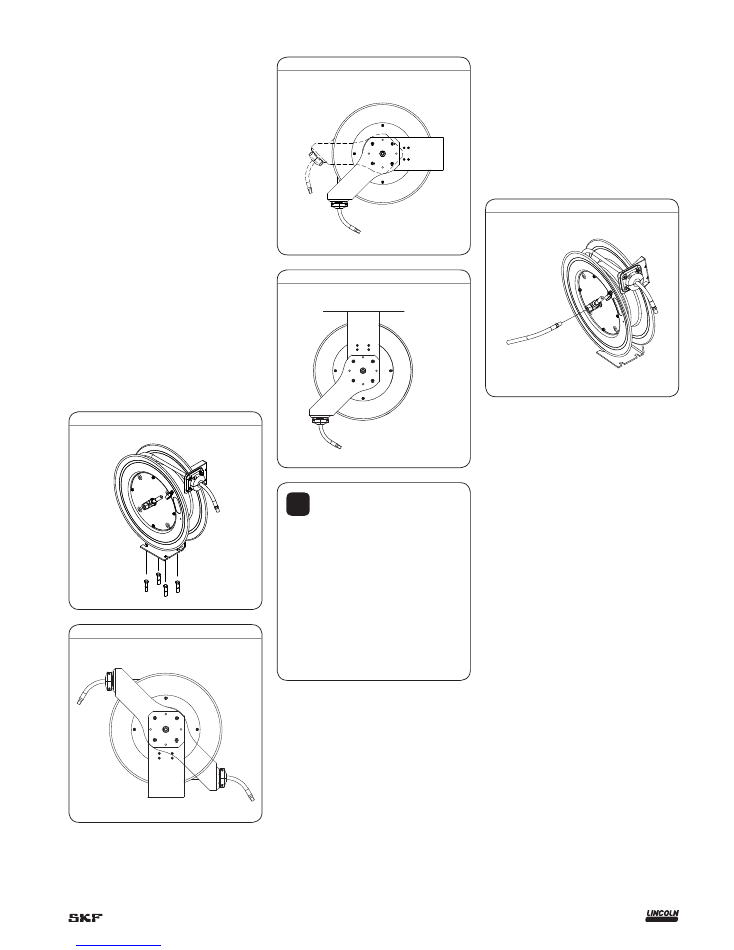
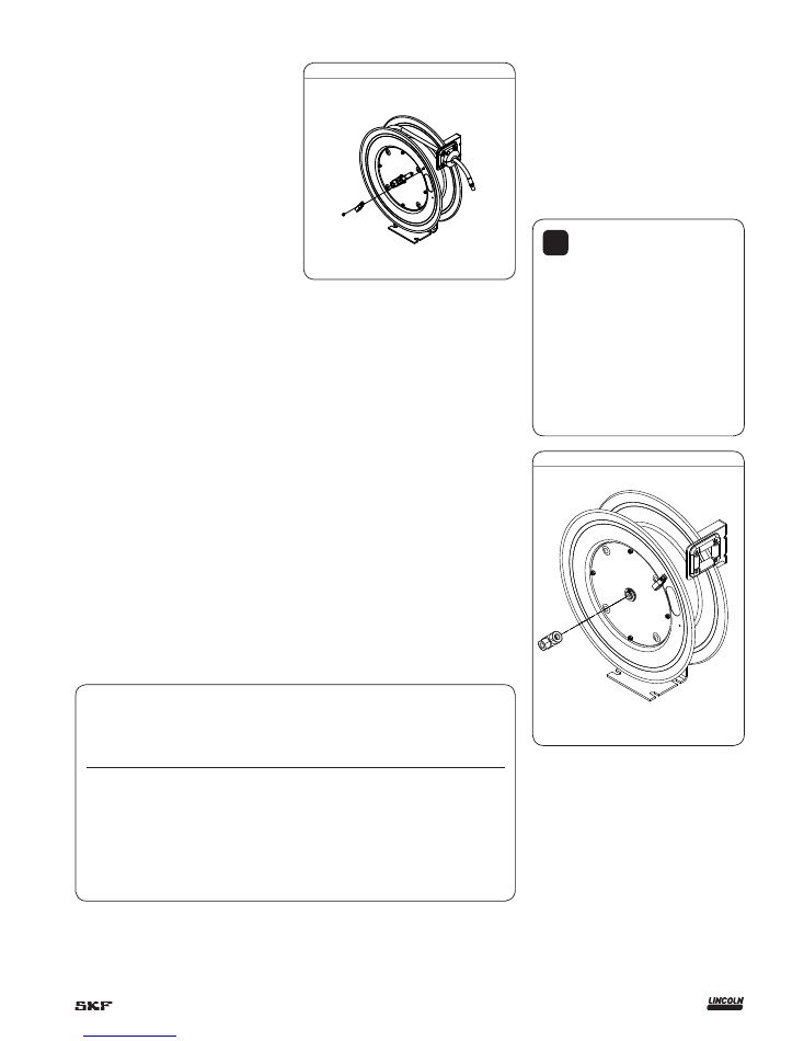
Fig. 1
Mount hose reel
Prior to mounting the hose reel, ensure that
the supply line pressure does not exceed the
maximum working pressure of the hose
reel.
Do not exceed the maximum installation
height of 16 ft.
(4,8 m)
.
Unpack and inspect the reel for damage.
Turn the spool by hand to check for a
smooth operation.
Position the reel on the floor, wall or
ceiling (not recommended for mobile
applications).
Secure into place using four mounting
bolts (not included).
Depending on where the reel is placed, it
may be necessary to adjust the hose
bumper and guide arm to use the hose
properly.
Refer to
page 4
to adjust the hose
bumper and reposition the guide arm.
Fig. 2
Mounting applications
Fig. 3
Mounting applications
Fig. 4
Mounting applications
!
Notice
Do not use rigid plumbing
.
Use flexible hose connection at input.
Do not exceed recommended torque
of 70 ft.lbf.
(94 Nm)
.
Model 83753 requires
1
/
4
inch NPTF
hose and Model 83754 requires
1
/
2
inch
NPTF hose.
Connecting hose not included.
Fig. 5
Install connecting hose
1
Apply pipe thread sealant to threads on
reels.
2
Thread connecting hose onto input
† figure 5
.
3
Tighten connecting hose fitting to a
torque of 70 ft.lbf.
(94 Nm).
3
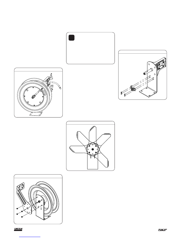
Adjust hose bumper
1
Pull out hose until latch pawl engages.
2
Loosen slotted screws shown in
fig. 6
.
3
Slide the bumper to desired position.
4
Tighten screws.
5
Pull hose to disengage latch pawl.
6
Allow hose to retract into reel.
Fig. 6
Remove guide arm
1
Pull out hose until latch pawl is engaged.
2
Remove slotted screws holding bumper in
place (
† fig. 6
).
3
Remove bumper.
4
Allow hose to retract into reel.
5
Remove 4 nuts holding guide arm on
base (
† fig. 7
).
6
Pull guide arm off of base.
Fig. 7
Position guide arm
1
Remove the guide arm.
Fig. 8
!
Notice
Recommended guide arm
positions for mounting applications are
shown in
figures 2, 3, and 4 on page 3
.
2
Position guide arm in one of five positions
shown in
fig. 8
.
3
Install and tighten four nuts on guide
arm.
4
Tighten drive spring by turning spool two
or three revolutions to engage latch pawl.
5
Pull hose through roller opening in guide
arm.
6
Position bumper on hose.
7
Install and tighten screws in bumper.
Refer to (
† fig. 6
)
Replace latch pawl
1
Retract hose onto reel until bumper is
against guide rollers and latch pawl is not
engaged.
2
Remove nuts that fasten latch pawl
assembly with socket-head cap screws.
3
Replace latch pawl assembly and tighten
nuts.
Fig. 9
4
Replace hose
Remove the hose
1
Pull out the hose leaving 2 to 3 ft.
(0,6
to
0,9 m)
on the spool.
2
Engage the latch pawl.
3
Remove the screw nuts on the inside of
the spool (
† fig. 10
).
4
Remove the hose clamp.
5
Unthread the hose at the connection to
the swivel.
6
Use a wrench on both fittings or the
swivel may be damaged.
7
Remove the hose.
Install hose
1
Route the hose through the guide arm
rollers and opening of the spool.
2
Apply thread tape or sealant to hose
threads.
3
Screw hose fitting into threaded fitting on
swivel.
4
Tighten connection with a wrench on both
fittings.
5
Install the hose clamp (
† fig. 10
).
6
Install hose bumper on working end of
hose.
7
Disengage latch pawl and allow hose
to retract.
Fig. 10
Replace swivel
1
Remove the hose (
† Replace hose
).
2
Remove swivel by unscrewing the
threaded stem from the main shaft
(
† fig. 11
).
3
Replace swivel by screwing threaded stem
of swivel into main shaft of reel.
4
Replace the hose.
Fig. 11
Service parts
Model
Model
Item
Number
Description
Quantity
83753
3
/
8
in. x 50 ft.
(
0,37 mm x 15,24 m
)
83754
1
/
2
in. x 50 ft
(
12,7 mm x 15,24 m
)
1
Swivel assembly
1
/
4
inch NPT 1
279135
279136
15
Hose clamp
1
272167
272168
18
Ratchet and spacer assembly 1
279134
279134
28
Hose assembly
1
278749
278752
29
Bumper assembly
1
278665
278664
32
Latch pawl assembly
1
279133
279133
!
Notice
Do not use rigid plumbing
.
Use flexible hose connection at input.
Do not exceed recommended torque
of 70 ft.lbf.
(94 Nm)
.
Model 83753 swivel assembly has
1
/
4
inch NPTF internal threads and Model
83754 swivel assembly has
1
/
2
inch
NPTF internal threads.
Connecting hose not included.
5
1
2
3
4
5
6
7
8
9
10
11
12
13
14
15
16
17
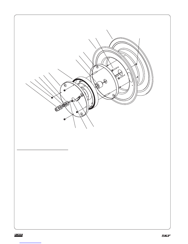
Parts
Illustrated parts breakdown
Item no. Description
Quantity
1
Swivel assembly
1)
1
2
Nut M6
2)
4
3
Snap ring 19
2)
1
4
Washer 18
2)
1
5
Adjust washer
2)
3
6
Spring case cover
2)
1
7
Drive spring assembly
2)
1
8
Arbor
2)
1
9
Spring case stud
2)
4
10
Spring case
2)
1
11
Spring case sheave
2)
1
12
Hex washer screw
2)
3
13
Sheave flange
2)
1
14
Screw M5 x 12
2)
1
15
Hose clamp
1)
1
16
Nyloc nut M5
2)
1
17
Screw M10 x 30
2)
1
1)
Refer to service parts table on
page 5
for part numbers.
2)
Not available for order.
6
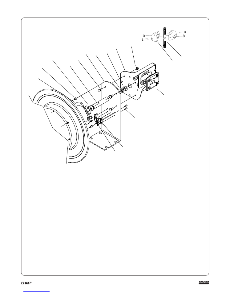
18
19
20
21
22
23
24
25
26
27
30
31
32
33
28
29
Illustrated parts breakdown
Item no. Description
Quantity
18
Ratchet and spacer assembly
1)
1
19
Step nut
2)
4
20
Main shaft spacer
2)
1
21
Main shaft
2)
1
22
Bolt GB/T 12 M8 x 18
2)
4
23
Base
2)
1
24
Washer GB/T 93 16
2)
1
25
Nut GB/T6170 M16
1
26
Guide arm
2)
27
Nyloc nut M8
2)
4
28
Hose assembly
1)
1
29
Bumper assembly
1)
1
30
Universal roller
2)
1
31
Screw M5 x 12
2)
4
32
Latch pawl assembly
1)
1
33
Nyloc nut M5
2)
5
1)
Refer to service parts table on
page 5
for part numbers.
2)
Not available for order.
7

This page intentionally left blank.
8

This page intentionally left blank.
9

This page intentionally left blank.
10

Lincoln industrial
standard warranty
Standard limited warranty
Lincoln warrants the equipment manufac-
tured and supplied by Lincoln to be free
from defects in material and workmanship
for a period of one (1) year following the
date of purchase, excluding there from any
special, extended, or limited warranty pub-
lished by Lincoln. If equipment is deter-
mined to be defective during this warranty
period, it will be repaired or replaced, within
Lincoln’s sole discretion, without charge.
This warranty is conditioned upon the
determination of a Lincoln authorized rep-
resentative that the equipment is defective.
To obtain repair or replacement, you must
ship the equipment, transportation charges
prepaid, with proof of purchase to a Lincoln
Authorized Warranty and Service Center
within the warranty period.
This warranty is extended to the original
retail purchaser only. This warranty does not
apply to equipment damaged from accident,
overload, abuse, misuse, negligence, faulty
installation or abrasive or corrosive material,
equipment that has been altered, or equip-
ment repaired by anyone not authorized by
Lincoln. This warranty applies only to equip-
ment installed, operated and maintained in
strict accordance with the written specifica-
tions and recommendations provided by
Lincoln or its authorized field personnel.
This warranty is exclusive and is in lieu
of any other warranties, express or
implied, including, but not limited to, the
warranty of merchantability or warranty
of fitness for a particular purpose.
War-
ranty on items sold by Lincoln, but not
manufactured by Lincoln are subject to
the warranty consideration, if any, of
their manufacturer (such as hoses,
hydraulic and electric motors, electrical
controllers, etc.) Assistance in making
such warranty claims can be offered as
required.
In no event shall Lincoln be liable for inci-
dental or consequential damages. Lincoln’s
liability for any claim for loss or damages
arising out of the sale, resale or use of any
Lincoln equipment shall in no event exceed
the purchase price. Some jurisdictions do
not allow the exclusion or limitation of inci-
dental or consequential damages, therefore
the above limitation or exclusion may not
apply to you.
This warranty gives you specific legal
rights. You may also have other rights that
vary by jurisdiction.
Customers not located in the Western
Hemisphere or East Asia: Please contact
Lincoln GmbH and Co. Kg, Walldorf,
Germany, for your warranty rights.
Special limited warranties
Special limited 2 year warranty
SL-V series, single injectors
–
85772,
85782, and replacement injectors
–
85771, 85781
Lincoln warrants the SL-V Injector series to
be free from defects in material and work-
manship for two (2) years following the date
of purchase. If an injector model (single or
replacement) is determined to be defective
by Lincoln, in its sole discretion, during this
warranty period, it will be repaired or
replaced, at Lincoln’s discretion, without
charge.
Special limited 5 year warranty
series 20, 25, 40 bare pumps, pmv bare
pumps, heavy duty and 94000 series bare
reels
Lincoln warrants series 20, 25, 40 bare
pumps, PMV bare pumps, heavy duty
(82206), mini bench (81133, 81323), and
all 94000 LFR series (single arm and dual
arm) bare reels to be free from defects in
material and workmanship for five (5) years
following the date of purchase. If equipment
is determined by Lincoln, in its sole discre-
tion, to be defective during the first year of
the warranty period, it will be repaired or
replaced at Lincoln’s discretion, without
charge. In years two (2) and three (3), the
warranty on this equipment is limited to re-
pair with Lincoln paying parts and labor
only. In years four (4) and five (5), the war-
ranty on this equipment is limited to repair
with Lincoln paying for parts only.
Special limited 5 year warranty
limited oil meters, limited fluid control
valves, aod (air-operated diaphragm
pumps)
Lincoln warrants the 712 series control
valves, 912 series lube meters, electronic
lube meters (980, 981, 982 series), our
universal inline digital meters (812/813
series), and our AOD pump offering to be
free from defects in material and workman-
ship for five (5) years following the date of
purchase. If either is determined to be
defective by Lincoln, in its sole discretion,
during the warranty period, they will be
repaired or replaced, at Lincoln’s discretion,
without charge.
Special DEF (diesel exhaust fluid) limited
warranty
DEF products are warranted to be free from
defects in material and workmanship for a
period of one (1) year following the date of
purchase. The following exceptions to the
standard warranty period are in effect:
• 85700-30/85700-50 DEF hose reels
(bare reel only),
277251/277252 AC DEF pumps, and
277256 and 277257 DEF meters are
warranted for two (2) years from date of
purchase.
• 85623 DEF AOD
(air operated diaphragm) pumps
are covered under the standard five (5)
year AOD pump warranty.
If either is determined to be defective by
Lincoln, in its sole discretion, during the
warranty period, they will be repaired or
replaced, at Lincoln’s discretion, without
charge.
Lincoln Industrial contact information
To find Lincoln Industrial’s nearest service
center call the following number;
customer service 314-679-4200
(international number 01-314-679-4200)
or you may also use our website
www.lincolnindustrial.com
11

® SKF is a registered trademark of the SKF Group.
® Lincoln is a registered trademark of Lincoln Industrial Corp.
© SKF Group 2014
The contents of this publication are the copyright of the publisher and may not be reproduced (even extracts) unless prior written permis-
sion is granted. Every care has been taken to ensure the accuracy of the information contained in this publication but no liability can be
accepted for any loss or damage whether direct, indirect or consequential arising out of the use of the information contained herein.
SKF
PUB LS/I1 14723 EN.R1
· June 2014 ·
Form 404665A
.
Seals
Bearings and
housings
Lubrication
systems
Mechatronics
Services
The Power of Knowledge Engineering
Combining products, people, and application-
specific knowledge, SKF delivers innovative
solutions to equipment manufacturers and pro-
duction facilities in every major industry world-
wide. Having expert ise in multiple competence
areas supports SKF Life Cycle Management, a
proven approach to improv ing equipment reliabil-
ity, optimizing operational and energy efficiency
and reducing total cost of ownership.
These competence areas include bearings and
units, seals, lubrication systems, mecha tronics,
and a wide range of services, from 3-D computer
modelling to cloud-based condition monitoring
and asset management services.
SKF’s global footprint provides SKF customers
with uniform quality standards and worldwide
product availability. Our local presence provides
direct access to the experience, knowledge and
ingenuity of SKF people.
SKF BeyondZero is more than our climate strategy
for a sustainable environment: it is our mantra; a
way of thinking, innovating and acting.
For us, SKF BeyondZero means that we will
reduce the negative environmental impact from
our own operations and at the same time, increase
the positive environmental contri bution by offering
our customers the SKF BeyondZero portfolio of
products and services with enhanced envir on-
mental performance characteristics.
For inclusion in the SKF BeyondZero portfolio,
a product, service or solution must deliver signifi-
cant environmental benefits without serious
envir onmental trade-offs.
lincolnindustrial.com
skf.com/lubrication