Full Text Searchable PDF User Manual
www.LEGALETT.com
Operating voltage ...............................1 P - 230V 60Hz
Fan motor power consumption ............................225W
Breaker rating (GFI required) ................................. 30A
Output, electrical.......................................... 4 x 1250W
Air flow with:
8 - 100 mm (4") pipes.................
≥
900 m
3
/h / 530 CFM
Air flow with:
20 - 50 mm (2") pipes.................
≥
750 m
3
/h / 440 CFM
TECHNICAL DATA
FUNCTION
1 P - 230V 60Hz
Thermostat 1-4
30A Circuit Breaker
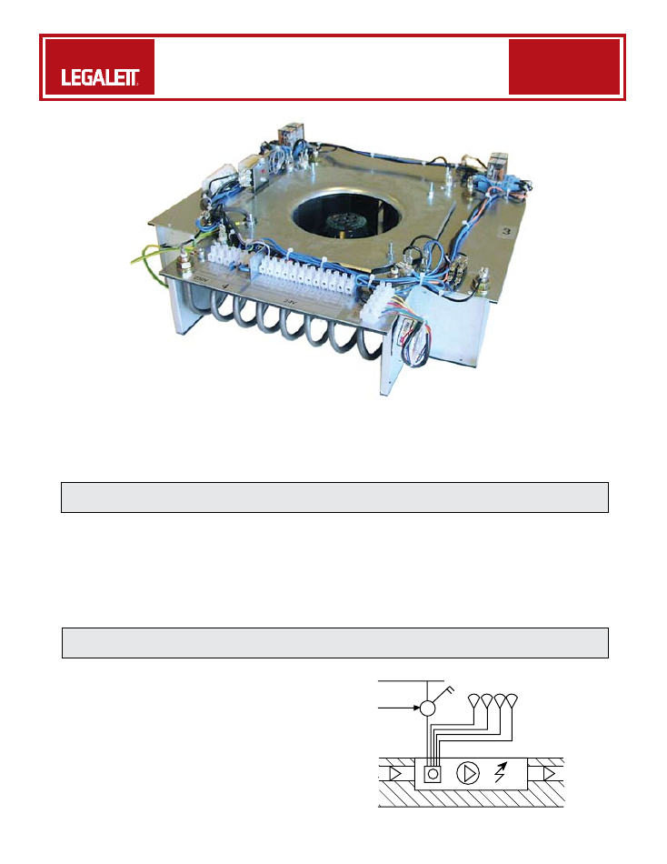
The 4000E-24 heating-unit is installed in the foundation
slab or suspended floor, and contains a fan and
four heating elements, with contactors that are
controlled by 1 - 4 external electric room thermostats.
This data is generic.
Each Legalett installation is unique. Refer to customized
specifications on your installation design drawing for
actual design parameters.
The 4000E-24 is controlled by one (single zone) to four
(quad zone) external electric room thermostats. These
external thermostats operate the contactors in the unit,
energizing the heating coil and fan when the room needs
heat. The unit is also equipped with seven overheating
protection devices.
When controlled by a programmable thermostat, the
4000E-24 can benefit from two-tiered energy rates for
night storage of less expensive energy in the LEGALETT
heated floor.
It is used together with heating unit box 4000A 100/100
(4"/100 mm spiral pipes) or with heating unit box
4000A 50/50 (2"/50 mm plastic pipes).
June, 2007
Revised:June, 2008
Form № 0535
Page 1 of 2
HEATING UNIT - 4000E-24
25
www.LEGALETT.com
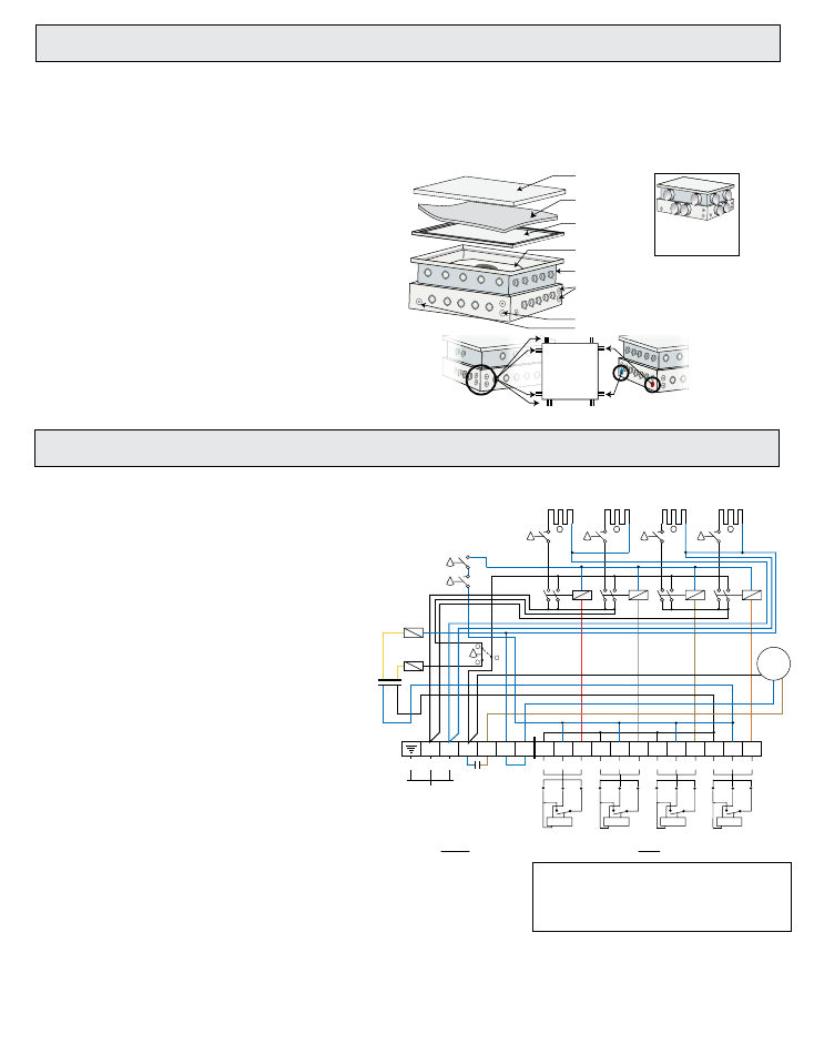
ASSEMBLY
ELECTRICAL CONNECTIONS
Install the heating unit boxes in the correct location,
with the height adjusted so that the lid is flush with the
concrete surface, before pouring the concrete. Refer
to the instructions on the box cover.
1. Run conduit from one of the cable inlets on the
box to the local disconnect for 230V power. Run
conduits from the remaining cable inlets to a
convenient location above the slab for each of the
24V thermostats.
2. (Optional) For future conversion to water insert,
connect the sleeves for the inlet and outlet water
pipes to the water pipe connections of the furnace
box. Install the water pipes, and make sure they
extend at least 100 mm (4") into the box. As well, run
a conduit for optional signal wiring to the boiler.
3. After the concrete has dried sufficiently with the
construction heater, prepare the box for the heating
unit according to the steps below, which are to
be performed by an authorized electrician and
plumber.
1. Check the electrical data on the unit so that
other installation materials are compatible. The
installation must be performed by an authorized
electrician.
2. Install a properly sized two-pole local disconnect to
enable total isolation for servicing. GFI protection
is required.
3. Use properly sized copper wire for connection to
the panel.
4. Connect thermostats.
5. Seal the conduits which run into the unit using a duct
sealing compound for both water and electrical, after
the water and electrical connections have been made,
for sound attenuation.
6. Install the heating unit cover. Test run for 1 hour
and then open for a check. If necessary clean,
check for dryness, and test run again. If moisture
is still present, re-install construction heater and
run until the system is dry.
7. Install the sound insulating foam-rubber mat
between the heating unit cover and the floor
hatch.
8. Install the floor hatch. If desired, use standard
transition trim between the hatch and the floor.
Overheating Protection
If the overheating protection has tripped, then complete
the following steps:
1. Turn off the power.
2. Carefully investigate the reason for the overheating.
Any repairs should only be performed by an
authorized electrician.
1
3
2
4
sound insulation
mat, 30 mm (1")
floor hatch
heating unit
cover
electrical connections
heating insert
heating unit box
hole for water pipe return for future
hole for water pipe inlet for future
water pipe
connections
for future
conversion to
water
electrical
connections
4000E-24
heating unit box
4000A 50/50 (2")
Heating unit box
4000A 100/100 (4")
is similar
4. Clean the furnace box carefully. No water or
dampness should be in the box or pipe system when
installing the permanent insert.
5. Install the heating unit insert with the terminal block
turned towards the electric connection conduit
openings.
26
1
2
3
4
5
6
7
8
9
10
11
12
L2
L1
1
1
1
1
1
1
1
K1
K2
K3
K4
1250W
1250W
1250W
1250W
75
° C
(167° F)
O.H.
110
º
C (230
º
F)
O.H.
50
o
T.B.
24V
Black
Blue
Br
o
w
n
1
2
3
R
C
W
C
230V
60Hz
30A
230V
24V
Thermostat 1
R
C
W
Thermostat 2
R
C
W
Thermostat 3
R
C
W
Thermostat 4
M
400mA
R C
W
R C
W
R C
W
R C
W
Fan
1
2
4
1
2
3
4
230V
400mA
75
° C
(167° F)
O.H.
75
° C
(167° F)
O.H.
75
° C
(167° F)
O.H.
110
º
C (230
º
F)
O.H.
Contactors marked K1 - K4
O.H.= Overheating protection device
If 1 - 3 thermostats are used, or if more than one thermostat
is installed in the same room, install a jumper between the
connection blocks 3, 6, 9 and 12 as required.
Refer to the floor plan for thermostat locations.