Full Text Searchable PDF User Manual

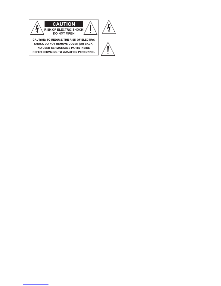
The lighting flash with arrowshad symbol within an
equilateral triangle is intended to alert the user to the
presence of uninsulated “dangerous voltages” within the
product’s enclosure, that may be of sufficient magnitude to
constitute a risk of electric schok to persons.
The exclamation point within an equilater triangle is
intended to alert the user to the presence of important
operating and maintenance (servicing) instructions in the
literature accompanyng the appliance.
IMPORTANT SAFETY INSTRUCTIONS
INSTRUCTIONS PERTAINING A RISK OF FIRE, ELECTRIC SHOCK OR INJURY A PERSONS
WARNING
- When using electric products, basic precautions should always be followed, including the fol-
lowing.
1
. Read all the SAFETY INSTRUCTIONS before using the product.
2.
A reduce the risk of injury, close supervision is necessary when the product is used near children.
3.
Do not use this product near water - for example, near a bathtub, washbowl, kitchen sink, in a wet base-
ment or near a swimming pool or the like.
4.
This product in combination with an amplifier, may be capable of producing sound levels that could cause
permanent hearing loss. Do not operate for a long period of time at high volume level or at level that is
uncomfortable. If you experience any hearing loss or ringing in the ears, you should consult an audiologist.
5.
This product should be located so that its location or position does not interfere with its proper ventilation.
6.
This product should be located away from heat sources such as radiators, heat register or other product
that produce heat.
/.
The product may be connected a power supply only of the type described on the operating instructions or
as marked on the product.
8.
The product may be equipped with a polarized line plug (one blade wider then the other). This is a safety
feature. If you are unable a insert the plug into the outlet, contact an electrician a replace your obsolete
outlet. Do not defeat the safety purpose of the plug.
9.
The power-supply cord of the product should be unplugged from the outlet when left unused for a long
period of time. When unplugging the power-supply cord, do not pull on the cord, but grasp it by the plug.
10.
Care should be taken so that object do not fall and liquid are not spilled into the enclosure through
openings.
11.
The product should be serviced by qualified service personnel when:
A.
The power-supply cord or the plug has been damaged; or
B.
Objects have fallen, or liquid has been spilled into the product; or
C.
The product has been exposed to rain; or
D.
The product does not appear to operate normally or exhibits a marked change in performance; or
E.
The product has been dropped or the enclosure damaged.
12.
Do not attempt to service the product beyond that described in the user-maintenance instructions.
All other servicing should be referred to qualified service personnel.
13. WARNING
- Do not place objects on the product’s power cord or place it in a position where anyone
could trip over, walk on or roll anything over it. Do not allow the product to rest on or to be installed over
power cords of any type. Improper installations os this type create the possibility of fire hazard and/or per-
sonal injury.
SAVE THESE INSTRUCTIONS
2
Connection to the mains supply
The apparatus has its own built-in power supply. Before switching on the unit, make certain that the mains voltage matches
that shown on the rear (a tolerance of up to ±10% is acceptable).
Before connecting or disconnecting the power cord, make certain the ON/OFF switch is in the OFF position OFF.
Switching on and off
CAUTION: before switching on or off, make certain the sound system’s amplifiers are off or turned down: this will avoid
signal peaks, which are annoying and sometimes dangerous (particularly for speaker enclosures).
Connecting and preventing or identifying interference
First of all, check that the apparatus is installed in a place free from industrial or RF (radio frequency) interference. Avoid
installing your equipment very near radio or TV sets, mobile phones, etc., as these can cause noisy interference.
When connecting the other parts of your sound system, watch out for the so-called “ground loops”, which could cause hum
and jeopardize the products’s excellent Sound-to-Noise and low distortion characteristics.
The best way (even if not always feasible) to avoid ground loops is to connect the electric ground of all the equipment to a
single central point (“star” system). In this case, the central point can be the mixer.
To avoid or solve hum and buzzing troubles, try different combinations of lifting grounds on units that are supplied with
ground lift switches or make sure all chassis are connected to earth ground, either through the A.C. power cord ground or by the
front panel rack mount screws.
CAUTION: before changing your grounds around, always turn your amplifiers down.
Protection and maintenance
Don’t force knobs, switches or connectors: these are designed and manufactured to respond to light pressure and could be
damaged if used with excessive force.
Take care of your connector cables, a very frequent cause of small/big problems. Always grip them by the connector, avoid
pulling them forcefully and wind them without forming knots or sharp bends: they’ll last longer this way, and be more reliable, which
is a definite advantage.
Avoid exposing the product to strong direct sunlight, high temperatures or intense vibrations, in very dusty or particularly
damp surroundings or, even worse, in the rain: this will help to avoid the risk of faulty operation, deterioration or even shock electric
shocks and fires.
The product is built in shock-resistant material. Nevertheless, protect it during transport with a flight-case to avoid the risk of
any casual accidents.
When you’ve finished using the apparatus, it’s always advisable to protect it from dust, but any dust that does form should
be removed using a cloth or a soft brush. Never use alcohol, acetone or any solvents.
The apparatus does not require any other maintenance.
In the event of breakdown
All user-adjustable parts are external and easily accessed (except for the shorting connector CN4 -see “Low-Summing”
configuration). In the event of a breakdown, do not open the apparatus, but contact the nearest Generalmusic/Lem Service
Centre.
Keeping the documentation
Keep this user’s manual for future consultation. Also remember that the mixer will get a better price on the secondhand
market if (as well as being in good condition) it has its original documentation and packaging.
Warnings and Installation
Warnings and Installation
3
READ BEFORE USING
Before starting to use the crossover in your sound system there is some information you should know and procedures you
should follow.
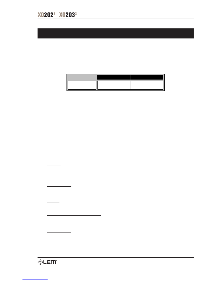
The XO 202 and XO 203 are fourth order Linkwitz-Riley electronic crossovers.
These units can be used both in stereo and in mono modes, allowing the following configurations:
XO 202
XO 203
STEREO MODE
2-WAY
3-WAY
MONO MODE
3-WAY
4-WAY
Stereo an mono modes can be easily set by pushing a switch and connecting Inputs and Ouputs properly: no patch cords
required.
Inputs & Outputs
All inputs and outputs are floating and balanced when connected (via a tip, ring, ...) to other floating and balanced equip-
ment. Any combination of balanced and unbalanced operation is permitted (see also “Connection Cables”).
CD Boost
The Constant Directivity horn equalization circuit is to be used with horns that require a high frequency boost. The provided
boost is +3dB @ 3.5kHz rising 6dB per octave to 22.5kHz.
Consult your horn manufacturer to determine whether it is needed in your circumstance.
No changes need to be made to operate without the constant directivity boost.
If the constant directivity equalization circuit is desired on a particular channel then depress the corresponding switch
labeled “CD BOOST”. There is one switch for each channel located near to the input socket. If two or more channels are ganged
together, then use only the switch near to the used input socket (the switch near to the unused input socket has no effect on the
circuit when ganged).
Clip LED
This LED will light when output capability is being exceeded with clipping distortion. Occasional flickering of the Clip LED is
acceptable, but if it remains on continuously you should turn down the level control or reduce the output level of the preceding
component to avoid audible distortion.
Range x1 & x10
(XO 202 only)
This switch sets the cut off frequency adjusted by the LOW-HIGH Crossover frequency knob as follows:
OFF
: Frequency x1 =
80Hz
-
920Hz
ON
: Frequency x10
=
800Hz
-
9200Hz
CAUTION: to prevent transients and possible equipment damage, never change the frequency range switch from the x1
position to x10 (or vice versa) with the crossover output levels passing signal.
LOW, MID & HIGH Phase Inversion
The Phase switches invert the phase between the speakers. Use them when you feel a bad sound continuity between the
LOW, MID and HIGH ranges.
LOW Summing
(for qualified personnel and/or advanced users only)
The XO 202 and XO 203 are designed to sum alI or any of the LOW outputs if desired.
The shorting connector “CN4” must be removed from the channels being summed and should, for best results, be in place
when no summing is desired. Shorting connector “CH4” is located nearly in the center at the two pieces board. You can easily find
it while the top plate opened.
Getting Started
Getting Started
4
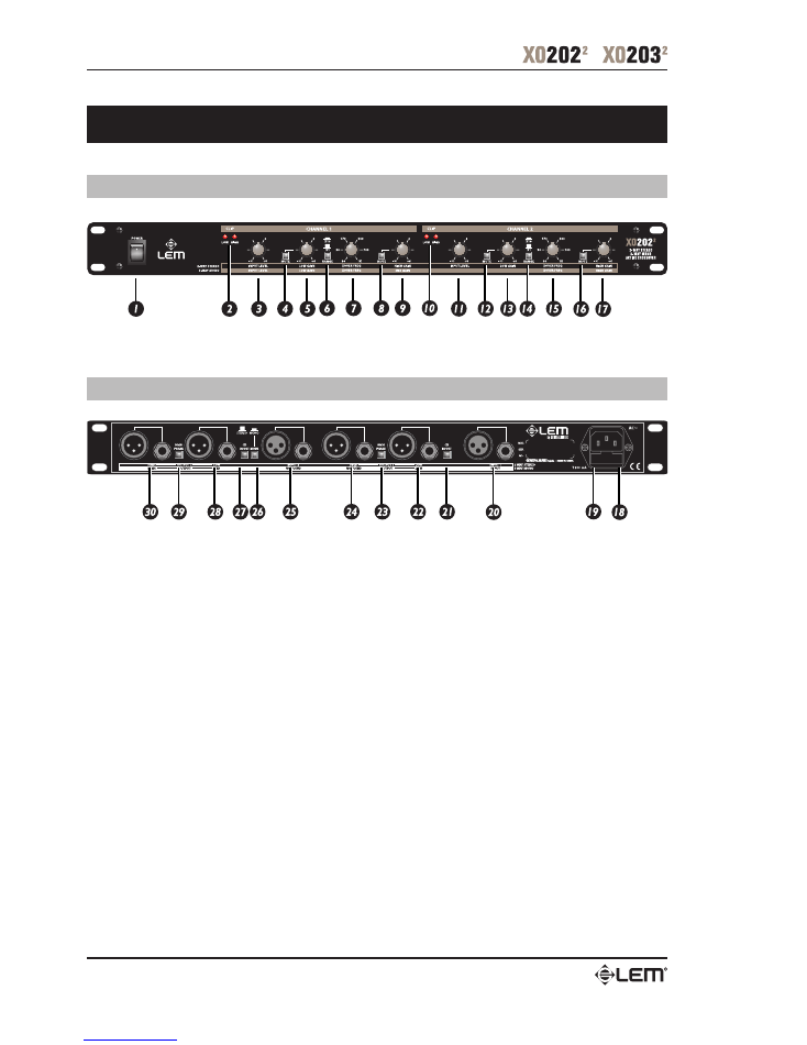
XO 202
2-way stereo / 3-way mono active crossover
XO 202 Front Panel
XO 202 Rear Panel
XO 202 2-way stereo / 3-way mono active crossover
5
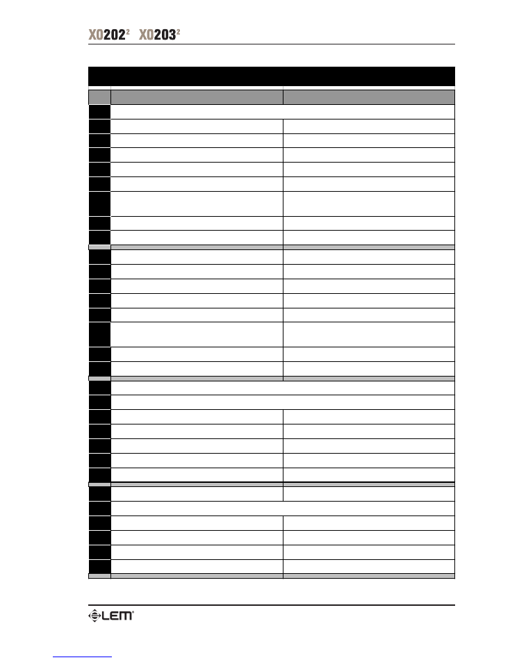
2-WAY STEREO MODE
3-WAY MONO MODE
1
2
Ch1 LOW & Ch1 HIGH Clip LEDs
LOW & MID Clip LEDs
3
Ch1 Input Level
Input Level
4
Ch1 LOW Mute
LOW Mute
5
Ch1 LOW Gain
LOW Gain
6
Ch1 LOW-HIGH Crossover Range
LOW-MID Crossover Range
7
Ch1 LOW-HIGH Crossover Frequency
800Hz - 10kHz (Range x10)
LOW-MID Crossover Frequency
80Hz - 1kHz (Range x1)
8
Ch1 HIGH Mute
( not used )
9
Ch1 HIGH Gain
( not used )
10
Ch2 LOW & Ch2 HIGH Clip LEDs
(ignored) & HIGH Clip LED
11
Ch2 Input Level
( not used )
12
Ch2 LOW Mute
MID Mute
13
Ch2 LOW Gain
MID Gain
14
Ch2 LOW-HIGH Crossover Range
MID-HIGH Crossover Range
15
Ch2 LOW-HIGH Crossover Frequency
800Hz - 10kHz (Range x10)
MID-HIGH Crossover Frequency
800Hz - 10kHz (Range x10)
16
Ch2 HIGH Mute
HIGH Mute
17
Ch2 HIGH Gain
HIGH Gain
18
19
20
Ch1 Line Input (Linked XLR-F & Jack)
Line Input (Linked XLR-F & Jack)
21
Ch1 Constant Directivity Boost
Constant Directivity Boost
22
Ch1 LOW Output (Linked XLR-M & Jack)
LOW Output (Linked XLR-M & Jack)
23
Ch1 HIGH Phase Inversion
MID Phase Inversion
24
Ch1 HIGH Output (Linked XLR-M & Jack)
( not used )
25
Ch2 Line Input (Linked XLR-F & Jack)
( not used )
26
27
Ch2 Constant Directivity Boost
( not used )
28
Ch2 LOW Output (Linked XLR-M & Jack)
MID Output (Linked XLR-M & Jack)
29
Ch2 HIGH Phase Inversion
HIGH Phase Inversion
30
Ch2 HIGH Output (Linked XLR-M & Jack)
HIGH Output (Linked XLR-M & Jack)
STEREO / MONO MODE
XO 202 • 2-way stereo / 3-way mono active crossover
Power Switch
Power Cord
Fuse holder
XO 202 2-way stereo / 3-way mono active crossover
6
XO 202 - Connection Examples
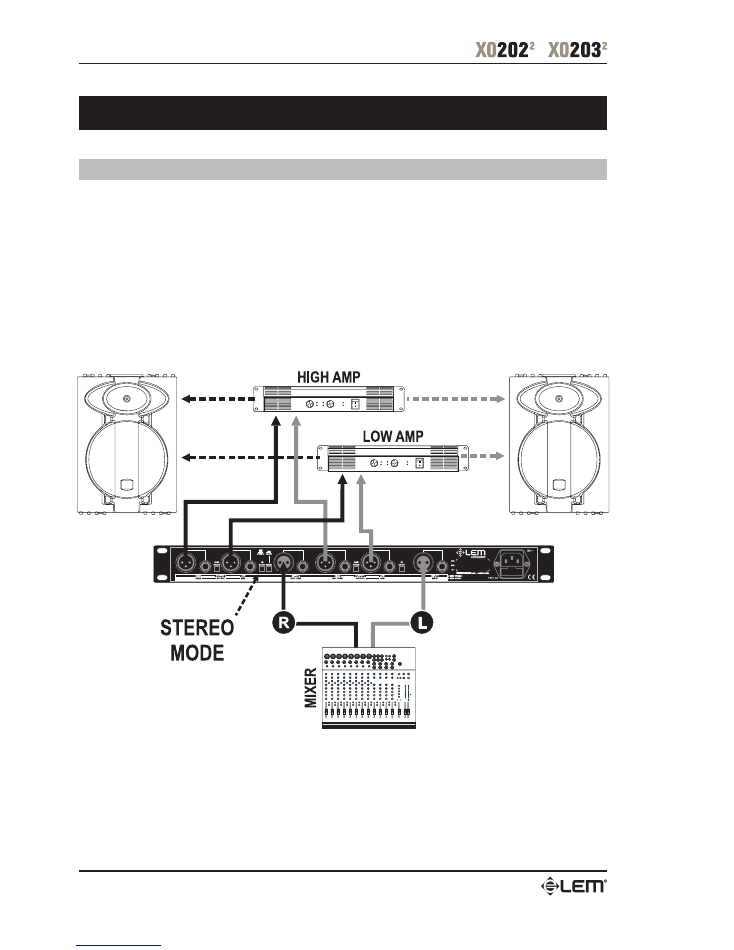
XO 202 - 2-way stereo
+
Set Mode switch to stereo Mode.
+
Plug the Left line-in to INPUT 1 and the Right line-in to INPUT 2.
+
Connect the LOW OUT 1 to the Left input of the Low frequency amplifier, and the LOW OUT 2 to the Right input of the Low
frequency amplifier.
+
Connect the HIGH OUT 1 to the Left input of the High frequency amplifier, and the HIGH OUT 2 to the Right input of the High
frequency amplifier.
+
Set the XOVER FREQ 1 and the XOVER FREQ 2 to x10 - LOW-HIGH Crossover control.
No patch cord required.
XO 202 - Connection Examples
7
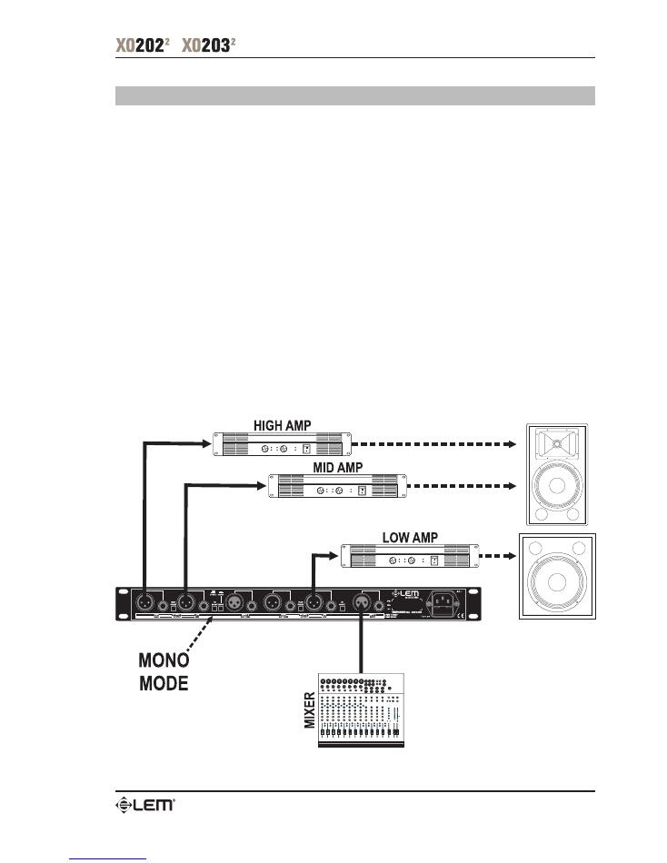
XO 202 - 3-way mono
Rear Panel
+
Set Mode switch to mono Mode.
+
Plug the line-in into INPUT 1.
+
Connect LOW OUT 1 to the Low frequency amplifier.
+
Connect LOW OUT 2 to the Midrange frequency amplifier.
+
Connect HIGH OUT 2 to the High frequency amplifier.
NOTE:
Do not connect anything into INPUT 2.
Do not connect anything from HIGH OUT 1.
(These inputs/outputs are automatically normalled when unplugged).
Front Panel
+
INPUT 1
main input level control
+
LOW Gain 1
Low frequency amplifier level control
+
XOVER FREQ 1
set to x1 - LOW-MID Crossover control
+
HIGH Gain 1
set to 0 and Mute
+
INPUT 2
set to 0
+
LOW Gain 2
Mid frequency amplifier level control
+
XOVER FREQ 2
set to x10 - MID-HIGH Crossover control
+
HIGH Gain
High frequency amplifier level control
No patch cord required.
XO 202 - Connection Examples
8
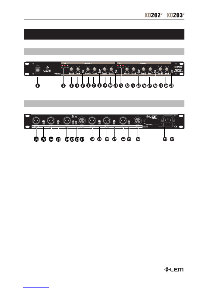
XO 203
3-way stereo / 4-way mono active crossover
XO 203 Front Panel
XO 203 Rear Panel
XO 203 3-way stereo / 4-way mono active crossover
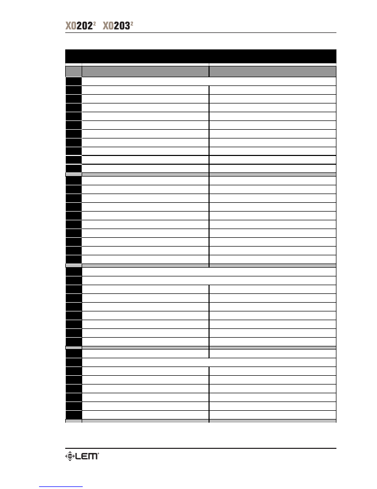
9
3-WAY STEREO MODE
4-WAY MONO MODE
1
2
Ch1 LOW, Ch1 MID & Ch1 HIGH Clip LEDs
HIGH Clip LED
3
Ch1 Input Level
Input Level
4
Ch1 LOW Gain
( not used )
5
Ch1 LOW Mute
( not used )
6
Ch1 LOW-MID Crossover Frequency
( not used )
7
Ch1 MID Gain
( not used )
8
Ch1 MID Mute
( not used )
9
Ch1 MID-HIGH Crossover Frequency
MID-HIGH Crossover Frequency
10
Ch1 HIGH Gain
HIGH Gain
11
Ch1 HIGH Mute
HIGH Mute
12
Ch2 LOW, Ch2 MID & Ch2 HIGH Clip LEDs
SUB, LOW & MID Clip LEDs
13
Ch2 Input Level
( not used )
14
Ch2 LOW Gain
SUB Gain
15
Ch2 LOW Mute
SUB Mute
16
Ch2 LOW-MID Crossover Frequency
SUB-LOW Crossover Frequency
17
Ch2 MID Gain
LOW Gain
18
Ch2 MID Mute
LOW Mute
19
Ch2 MID-HIGH Crossover Frequency
LOW-MID Crossover Frequency
20
Ch2 HIGH Gain
MID Gain
21
Ch2 HIGH Mute
MID Mute
22
23
24
Ch1 Line Input
Line Input
25
Ch1 Constant Directivity Boost
Constant Directivity Boost
26
Ch1 LOW Output
( not used )
27
Ch1 MID Phase Inversion
( not used )
28
Ch1 MID Output
( not used )
29
Ch1 HIGH Phase Inversion
( not used )
30
Ch1 HIGH Output
HIGH Output
31
Ch2 Line Input
( not used )
32
33
Ch2 Constant Directivity Boost
( not used )
34
Ch2 LOW Output
SUB Output
35
Ch2 MID Phase Inversion
LOW Phase Inversion
36
Ch2 MID Output
LOW Output
37
Ch2 HIGH Phase Inversion
MID Phase Inversion
38
Ch2 HIGH Output
MID Output
STEREO / MONO MODE
XO 203 • 3-way stereo / 4-way mono active crossover
Power Switch
Power Cord
Fuse holder
XO 203 3-way stereo / 4-way mono active crossover
10
XO 203 - Connection Examples
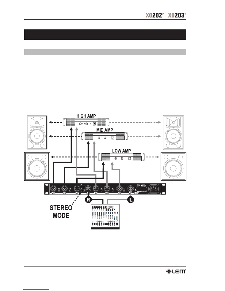
XO 203 - 3-way stereo
+
Set Mode switch to stereo Mode.
+
Plug the Left line-in to INPUT 1 and the Right line-in to INPUT 2.
+
Connect the LOW OUT 1 to the Left input of the Low frequency amplifier, and the LOW OUT 2 to the Right input of the Low
frequency amplifier.
+
Connect the MID OUT 1 to the Left input of the Mid frequency amplifier, and the MID OUT 2 to the Right input of the Mid
frequency amplifier.
+
Connect the HIGH OUT 1 to the Left input of the High frequency amplifier, and the HIGH OUT 2 to the Right input of the High
frequency amplifier.
No patch cord required.
XO 203 - Connection Examples
11
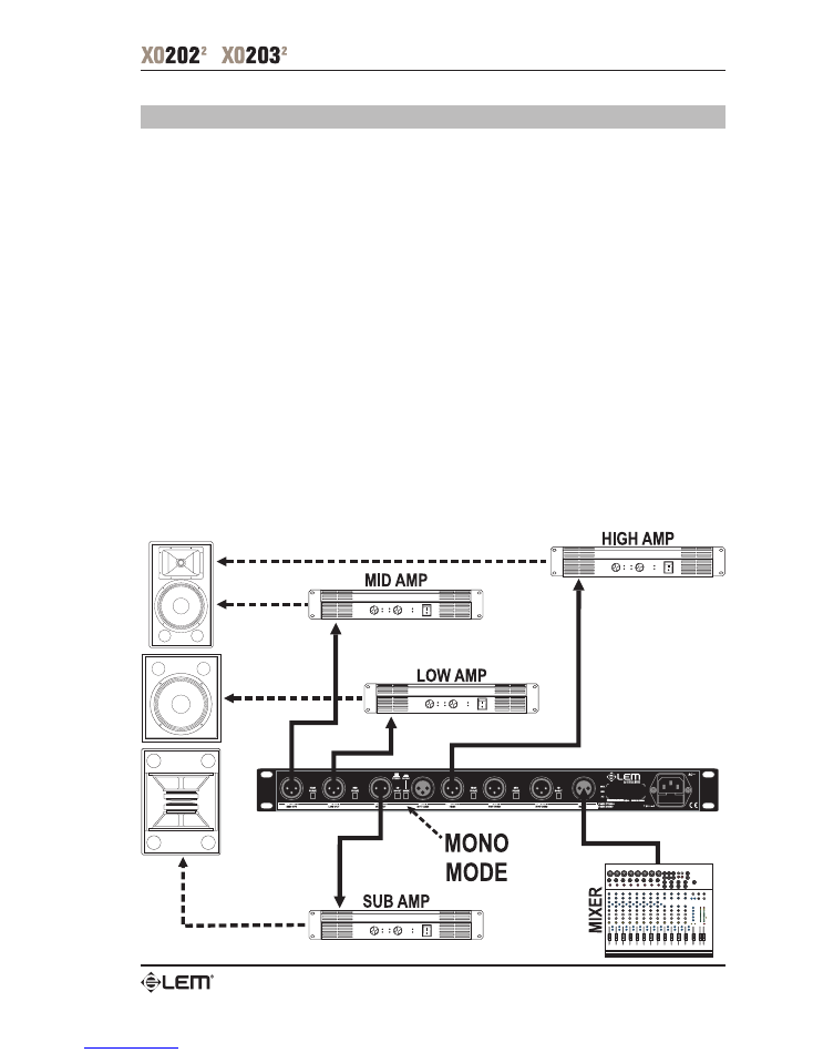
XO 203 - 4-way mono
Rear Panel
+
Set Mode switch to mono Mode.
+
Plug the line-in into INPUT 1.
+
Connect LOW OUT 2 to the Sub frequency amplifier.
+
Connect MID OUT 2 to the Low frequency amplifier.
+
Connect HIGH OUT 2 to the Midrange frequency amplifier.
+
Connect HIGH OUT 1 to the High frequency amplifier.
NOTE:
Do not connect anything into INPUT 2.
Do not connect anything from LOW OUT 1 and from MID OUT 1.
(These inputs/outputs are automatically normalled when unplugged).
Front Panel
+
INPUT 1
main input level control
+
LOW Gain 1
set to 0 and Mute
+
LOW-MID XOVER FREQ 1
(not used)
+
MID Gain 1
set to 0 and Mute
+
MID-HIGH XOVER FREQ 1
MID-HIGH Crossover control
+
HIGH Gain 1
High frequency amplifier level control
+
INPUT 2
set to 0
+
LOW Gain 2
Sub frequency amplifier level control
+
LOW-MID XOVER FREQ 2
SUB-LOW Crossover control
+
MID Gain 2
Low frequency amplifier level control
+
MID-HIGH XOVER FREQ 2
LOW-MID Crossover control
+
HIGH Gain 2
Mid frequency amplifier level control
No patch cord required.
XO 203 - Connection Examples
12
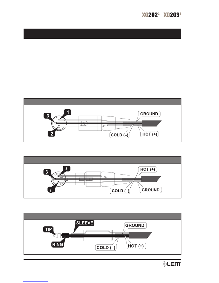
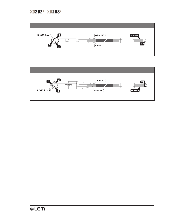
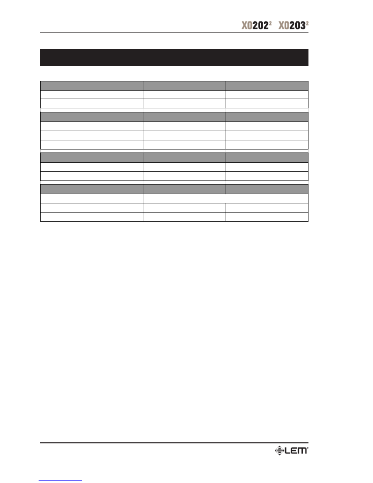
In this chapter you’ll find the wiring diagrams for the connectors to be used with your crossover.
Take care of the connector cables, always holding them by the connectors and avoiding knots and twists when coiling them:
this gives the advantage of increasing their life and reliability, which is always to your advantage.
Periodically check that your cables are in good condition, that they are correctly wired and that all their contacts are perfectly
efficients: a great number of problems (faulty contacts, ground hum, discharges, etc.) are caused entirely by using unsuitable or
faulty cables
Connection Cables
Balanced XLR-M
Balanced XLR-F
Balanced JACK
Connection Cables
13
XLR-M - JACK unbalanced link
XLR-F - JACK unbalanced link
Connection Cables
14
Technical Specifications
CROSSOVER FREQUENCY
XO 202
XO 203
LOW-MID
Range x1 80Hz - 1kHz
90Hz - 1kHz
MID-HIGH
Range x10 800Hz - 10kHz
800Hz - 10kHz
OUTPUT @ 0dB
LOW SECTION
< -106dBu
< -98dBu
MID SECTION
< -95dBu
HIGH SECTION
< -97dBu
< -93dBu
HUM & NOISE (20Hz - 20kHz)
Av=0dB, fc=800Hz
Av=0dB, fc=230Hz, 2.3kHz
S/N RATIO
118dB
114dB
POWER SUPPLY
DIMENSIONS ( W x H x D ) mm
483 x 44.5 x 216
483 x 44.5 x 216
WEIGHT
2.5 kg
2.5 kg
see label on the apparatus
Technical Specifications

FEDERAL COMMUNICATIONS COMMISSION
NOTE
: This equipment has been tested and found to comply with the limits for a Class A
digital device, pursuant to Part 15 of FCC Rules. These limits are designed to provide
reasonable protection against harmful interference when the equipment is operated in a
commercial environment. This equipment generates, uses and can radiate radio frequency
energy and, if not installed and used in accordance with the instruction manual, may cause
harmful interference in which case the user will be required to correct the interference at his
own expense.
CAUTION
: Changes or modifications to this product not expressly approved by the
manufacturer could void the user’s authority to operate this product.
Le informazioni contenute in questo documento sono state attentamente redatte e controllate. Tuttavia
non è assunta alcuna responsabilità per eventuali inesatezze.
Tutti i diritti sono riservati e in questo documento non può essere copiato, fotocopiato, riprodotto per intero
o in parte senza previo consenso scritto della
GENERALMUSIC
S.p.A.
GENERALMUSIC
si riserva il diritto di apportare senza preavviso cambiamenti e modifiche estetiche,
funzionali o di design a ciascun proprio prodotto.
GENERALMUSIC
non assume alcuna responsabilità sull’uso o sull’applicazione dei prodotti o dei circuiti
qui descritti.
STAMPATO IN ITALIA
The information contained in this publication has been carefully prepared and checked. However no
responsibility will be taken for any errors.
All rights are reserved and this document cannot be copied, photocopied or reproducted in part or
completely without written consent being obtained in advance from
GENERALMUSIC
S.p.A.
GENERALMUSIC
reserves the right to make any aesthetic, functional or design modification to any of its
products without prior notice.
GENERALMUSIC
assumes no responsibility for the use or aoolication of the products or circuits
described herein.
PRINTED IN ITALY

Sales Division: 47842 S.Giovanni in Marignano (RN) – Via delle Rose, 12 – tel. +39-0541-959511 – fax +39-0541-957404
Internet: http://www.lemaudio.com