Full Text Searchable PDF User Manual
PPE2
KDE
PPVE
KDE2
ELECTRIC INSTANTANEOUS WATER HEATER
Assembly and operating manual
Used product can’t be treated as general communal waste.
Disassembled appliance has to be delivered to the collec-
tion point of electrical and electronic equipment for recycling.
Appropriate utilisation of used product prevents potential
negative environmental influences that may occur as a result
of inappropriate handling of waste. In order to get more detailed
information about recycling this product you should contact the
local government unit, waste management service or the shop
where this product has been purchased.
This appliance is not intended for use by
persons (including children) with reduced
physical, sensory or mental capabilities
or lack of experience and knowledge,
unless they have been given supervision
or instruction concerning use of the appliance by a
person responsible for their safety. Children should
be supervised to ensure that they do not play with
the appliance.

3
GB-045BC_f.854
Safety instructions
1. Read and strictly follow the installation and operating instructions to ensure
a long life and reliable unit operation.
2. The unit is designed to be wall mounted.
3. The unit can only be used when in perfect technical condition and correctly
assembled.
4. If there is a non-return valve installed on the water supply pipe the safety valve
must be fitted between unit and non-return valve. This relates to KDE only.
5. Inlet and outlet pipes should not be made of plastic. This relates to KDE only.
6. The maximum inlet water temperature should not exceed 70°C.
7. The unit should always be vented before initial start-up. Vent the unit each time
after the water has been emptied from the heater or pipes (e.g. when water supply
system has been repaired or maintained).
8. Connection to the mains and measurement of fire protection effectiveness should
be made by a qualified person.
9. The unit has to be earthed.
10. The unit must be permanently connected to the mains which is equipped with
earth clamp.
11. Electric installation should be equipped with residual current protective devices
and other solutions which will ensure disconnecting the heater from the source
of power (intervals between all their poles should not be less than 3 mm).
12. The unit must not be installed in the place which is exposed to the danger of
explosion and place in which the temperature may go down below 0°C.
13. The unit must be kept in a place in which the temperature never go down below
0°C (there is a water inside the unit).
14. Do not use when the water has been emptied from the unit or pipes (e.g. when
water supply system has been repaired or maintained).
15. Unit’s cover must not be taken off while power is on.
16. Failure to install the filter on water supply pipe can cause unit damage.
17 Accumulation of limescale in parts of the water heater may cause limited water
flow and failure of the water heater. Failure of the heater and damages caused
by the limescale will not be covered by the warranty. The water heaters and
fittings must be descaled on the regular basis, the frequency of limescale removal
depanding on the quality of water.
18. Appropriate precaution must be taken while using hot water. Temperature of
water over 40°C may cause hot feeling and can be dangerous for children.
4
Installation - Assembly
1. Apply templete on place the unit will be
fitted. Mark points for drilling the holes for
fixing screws.
2. Bring the water system pipes and electric
supply cables to the marked places.
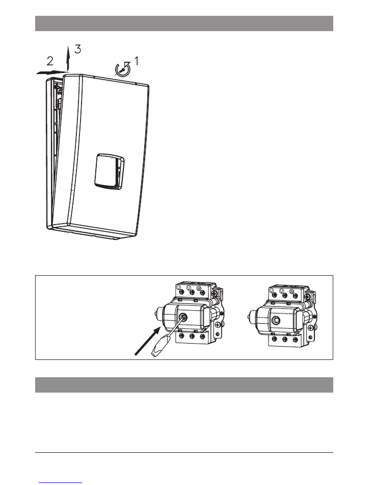
3. Take off the unit’s cover.
4. Run the supply wire through the hole and
fix the unit on the wall.
5. Connect the unit to the electric mains.
6. Remove rubber plugs from cold and hot
water fittings.
7. Connect the unit to the water supply system.
8. Open the cold water valve and check for
leaks.
9. Vent the water system. See section „Venting”
10. Make sure that the WC3 or WT3 temp.
limiter is at working position (the knob
should be pushed in).
11. Put the unit’s cover back.
12. Make sure that there is no access to live
parts through the holes at the back plate.
2
3
1
Safety temperature limiter
WC3/WT3
a) to switch on
b) WC3/WT3 on
a)
b)
Venting
1. Shut off electric supplies to the heater
2. Turn the flow on (turn the hot water tap on) in order to vent the water installation
(for about 15-30 seconds), until the flow of water becomes constant and even.
3. Switch on the electric supplies.
5
GB-045BC_f.854
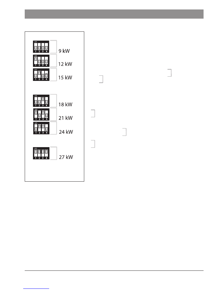
Configuration
Heating box size 15 kW
Heating box size 24 kW
Heating box size 27 kW
P
P
P
P
P
P
P
Before you supply voltage for the first time, make sure that
you set the heater’s power at appropriate value (always
consider the capacity of your home’s electrical system).
Notice: Configuration must be performed before initial
start-up when power supply is switched off. Set 2 (two)
switches at proper position to configure a heater. The
switches are located on electronic board. Each switch has
4 (four) positions, they are described as
P
(power settings)
and
F
(other settings). Switch on a power supply to upgrade
configuration. After you supply power to PPE2 or PPVE
a display will show: (PW...) - software version of control
panel, (MSP...) - software version of controller and the
value of rated power that has been set for the heater
(PPE2; PPVE).
P
switches settings (for PPE2, KDE2, PPVE):
•
1, 2 - rated power of heater,
•
3, 4 - type of heating box,
Do not reset
P
switches for KDE - keep factory
settings intact.
F
switches settings:
•
1, 2, 3 - do not change! keep factory settings intact,
•
4 - ON - blocks access to the heater’s settings.
In this case for PPE2 or PPVE, the display shows
the desired temperature value (which has been
adjusted before the heater is off), the heating icon
and other possible working characteristics.
grey square shows the switch
position
The heater is factory set at NORMAL mode (range of temperature regulation
from 30-60ºC) To use the heater for shower purposes it has to be changed to
SHOWER mode (range of temperature regulation from 30-55ºC). Change of the
modes can only be done by authorised service.
6
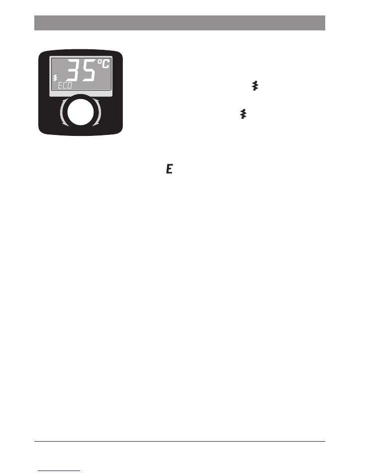
PPE2 Operation
The heater switches on automatically straight after reaching
the flow rate over 2,5 l/min. The temperature control system
adjusts the power rate according to the water flow rate,
required temperature and the temperature of water in
the mains. The LCD backlight and icon signalises the
heating operation. If the unit reach the maximum power
value which is too low for a given operating conditions the
LCD display will show flickering icon. The LED display
backlight also turns on while pushing or turning the setting
knob. The backlight will automatically turn off when the
heating operation is turned off, or if more than 50 seconds
have passed since the last adjustment.
If you block the unit by master appliance (NA entry) the display will show „NA BLOCK”.
If the fault occurs the display will show icon and error message.
Error messages:
•
ER>T INLET - inlet sensor failure,
•
ER> T MAX - temperature has exceeded the maximum value,
•
ER> AIR 1 - air bubbles in the heating box ,
If the display shows ER> T MAX, ER> AIR 1 the unit will stop heating.
The unit will not heat again until the failure is resolved and the appropriate value of
water flow is reached.
Temperature adjustment
Turn the knob to the right to increase the temperature value, or to the left to decrease it.
Push the knob to read the temperature value that is stored in memory. Push it again
to read the next stored value. You can switch between the following settings „ECO”,
„SINK” and „BATH”.
To change the temperature setting in memory:
•
select the temperature setting by pushing the control knob,
•
push the knob and keep for about 3 seconds until the value starts to flashing,
•
turn the knob to adjust the value,
•
push the knob to save the value.
Notice: save the new value within 10 seconds, otherwise you will lose it.
Configuration and parameters view
Set the minimum temperature value then push and keep knob for about 5 seconds
until the display shows „>SET TEMP”. Turn a knob to select the required value.
There are some parameters that are not changeable by the user (e.g. >T INLET, >FULL
POW), or can be used to change the work configuration only (e.g. display brightness,
electronic

7
GB-045BC_f.854
language version). To change the parameters value push (position flickering) and turn
the knob. Push the knob to confirm a changes.
Notice: confirm a new parameter value within 10 seconds, otherwise you will lose it.
The new parameter value will be saved when you exit menu using [>EXIT].
You can switch between the following parameters:
•
[>SET TEMP] temperature (min-max) - °C,
•
[>T INLET] inlet temperature value - °C,
•
[>T OUTLET] outlet temperature value - °C,
•
[>FLOW] flow rate - l/min,
•
[>FULL POW] percentage of maximum power with which the unit currently heats, -%,
•
[>T - h] work time,
•
[>BRIGH MIN] minimum brightness / stand-by-mode (0 - BRIGH MAX),
•
[>BRIGH MAX] maximum brightness / active (BRIGH MIN -25),
•
[>ENGLISH] select language version (POLSKI, FRANCAIS, ENGLISH, DEUTCH,
РУССКИИ, CESKY, ESPANOL),),
•
[>TEMP LIMIT] maximum temperature limit (min setting - max setting)
Notice: a new maximum temperature value will be saved in memory for other
temperature settings as well,
If you try to set the temperature above the adjusted maximum value the display will
show for about 1 second.
•
[>HE TEST] for authorized service only,
•
[>POWER SET] configured power value,
- push knob to check a software version (PW...,MSP...),
- restore to factory settings [FACTORY SET] or to restart controllers [RESET],
- push and keep knob (for about 5sec., until the display show [--]) to up grate
[FACTORY SET] and [RESET] function,
•
[>EXIT] save a new parameters and menu exit.
Notice: parameters view mode will automatically exit (without saving changes) after
5 minutes since the last adjustment.
8
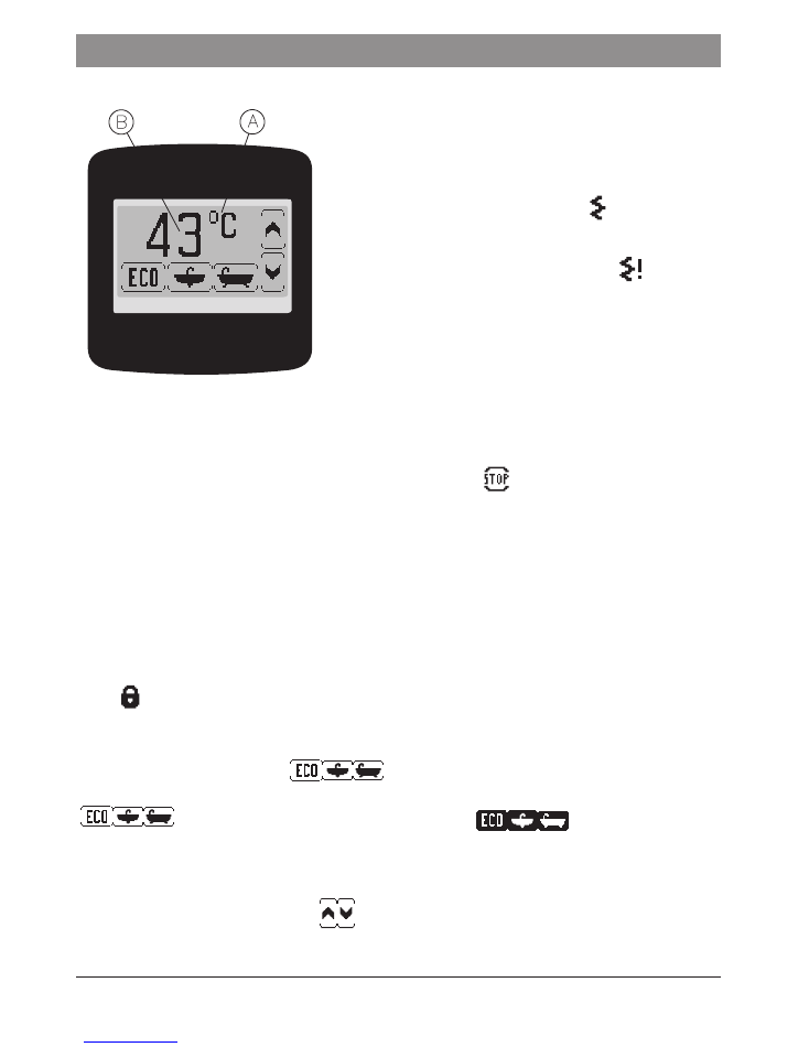
PPVE Operation
The heater switches on automatically straight after
reaching the flow rate over 2,5 l/min. The temperature
control system adjusts the power rate according to the
water flow rate, required temperature and the water
temperature in the mains.
The LCD red colour backlight and icon signalises
the heating operation. If the unit reach the maximum
power value which is too low for a given operating
conditions the LCD display will show . The LED
display backlight also turns. The heater switches
on automatically straight after reaching the flow
rate over 2,5 l/min. The temperature control system
adjusts the power rate according to the water
flow rate, required temperature and the water
temperature in the mains.
The LED display backlight also turns on while pushing or turning the setting knob.
The backlight will automatically turn off when the heating operation is turned off, or
if more than 30 seconds have passed since the last adjustment. If you block the unit
(NA entry) by master appliance the display will show
.
If the fault occurs the display will show error message:
•
ERR
Tin
- inlet sensor failure,
•
ERR
Tout
- outlet sensor failure,
•
ERR
Tmax
- temperature has exceeded the maximum value,
•
ERR
AIR1
- air bubbles in the heating box - equipment detection,
If the display shows
ERR
Tmax
,
ERR
AIR1
the unit will stop heating.
The unit will not heat again until the failure is resolved and the appropriate rate of
water flow is reached.
If you try to set the temperature above the adjusted maximum value the display will
show .
Temperature setting
Display shows three icons:
You can set the desired temperature value
(which has been stored in memory for each icon) by pressing one of them
- the icons will be displayed in inverse
.
To change the desired temperature value:
•
push the icon,
•
push the icon again and keep (for about 3 seconds) until the value starts to flicker,
•
to set the new value press
,
•
to save the value press icon.
Notice: save the new value within 10 seconds, otherwise you will lose it.
electronic
A
B
9
GB-045BC_f.854
The heater switches on automatically straight after reaching the flow rate over
2,5l/min. The temperature control system adjusts the power rate according to the water
flow rate, required temperature and the water temperature in the mains.
There are two indicators on the case:
-
green - power supply „on”,
-
red - heating „on”.
Other modes are shown by flickering green light.
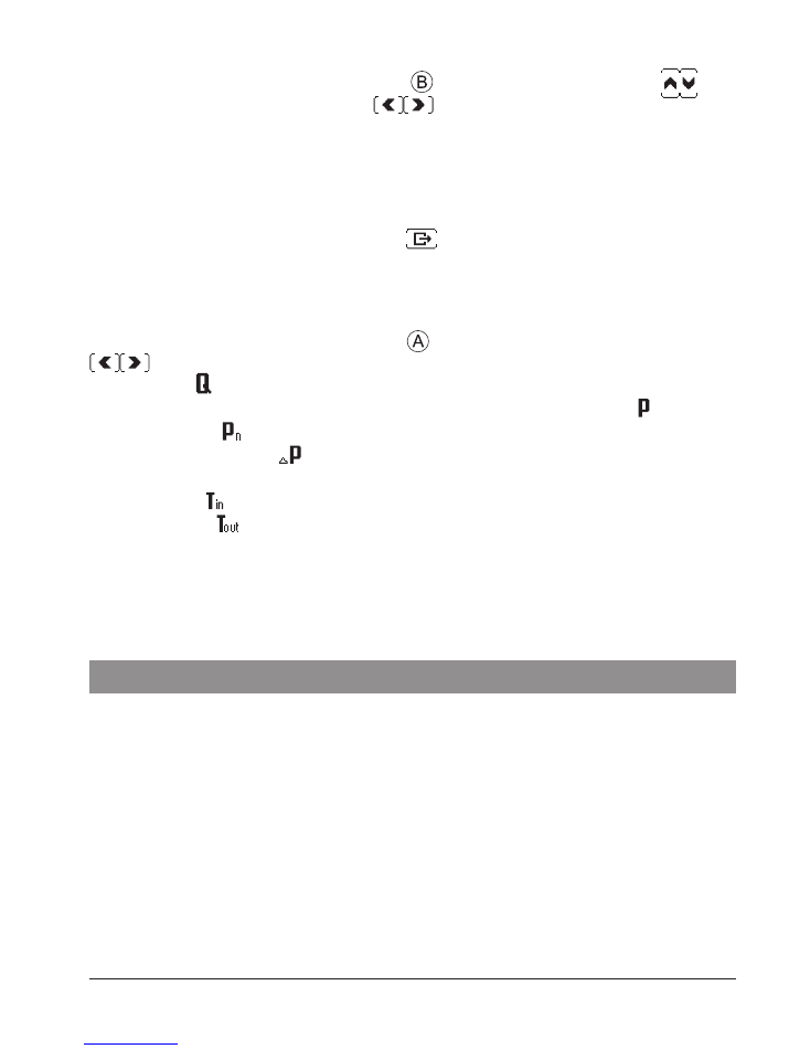
KDE, KDE2 Operation
Configuration
To enter the configuration mode press
. To adjust the value press
The
parameters will switch as you press
. You can switch between the following
parameters:
•
maximum temperature value,
•
display contrast (0-20),
•
display brightness in stand-by-mode (0-20) /brightness min. / (0 – brightness max.),
•
display brightness in active mode (0-20) /brightness max. / (brightness min. –20).
To exit parameters setting mode press
Notice: parameters setting mode will
automatically exit after 20 seconds since the last adjustment.
Parameters view
To enter the parameters view mode press .The parameters will switch as you press
. You can switch between the following parameters:
•
flow rate ,
•
percentage of maximum power with which the unit currently heats ,
•
rated power ,
•
correction of power ,
•
software details and work time,
•
inlet temp ,
•
outlet temp .
10
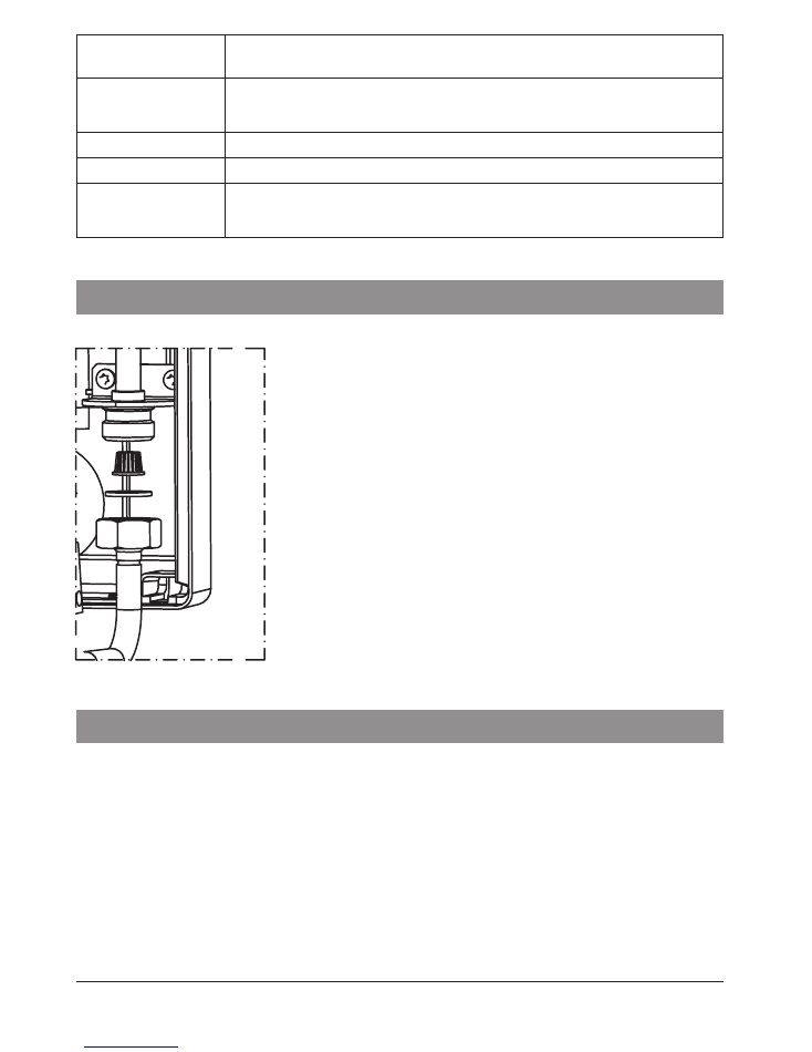
Maintenance
Filter cleaning:
1. Cut off power and cold water supplies.
2. Take off the unit’s cover.
3. Undo the inlet fitting - on the cold water side.
4. Take the filter out from the inlet fitting.
5. Clean up the filter.
6. Fix the filter back, put the gasket and do up the inlet
fitting.
7. Open the cut-off valve on cold water supply pipe -
check connections for leaks.
8. Fix the unit’s cover back.
9. Vent the water system - see Venting section.
Co-operation with other appliances
Unit is equipped with the BLOK and NA clamps.
BLOK - relay input that switches off the slave appliance, the circuit that is connected
to the BLOK clamps (max. 0,1A 250V-) will be opened at the time of heating operation
starts up.
NA - input that locks the unit operation, opened NA contacts locks the heating operation
- co-operation with the master appliance.
Wire (2 x 0,5mm
2
) for BLOCK and NA clamps should be run inside the unit on the
right side.
The wire connections must be performed by a qualified person.
Number of impulses
(green indicator)
description
1
The unit was switched off because the temperature has exceeded the
maximum value (fault signal will not disappear until the appropriate rate
of water flow is reached).
2
The unit was switched off by a master appliance.
3
The inlet temperature sensor failure.
4
The unit was switched off because the air bubbles in the heating box (the
unit will not heat again until the fault is resolved and the appropriate rate of
water flow is reached).
Technical data
The minimal resistivity of water at 15
0
C for PPE2, KDE2 , PPVE is 1100 Ω cm.
KDE.4
9
12
9
12
Rated power
kW
9
12
9
12
Rated voltage
240V~
230V~
Rated current
A
37,5
50
39,1
52,2
Efficiency (at Δt = 40°C and water pressure at 0,4 MPa) l/min
3,3
4,3
3,3
4,3
Min. connecting wires section
mm
2
3 x 10
3 x 6
3 x 10
Max. connecting wires section
mm
2
3 x 25
3 x 16
PPE2, PPVE, KDE2
9/11/12/15
17/18/21/24
27
Rated power
kW
9
11
12
15
17
18
21
24
27
Rated voltage
400V 3~
Rated current
A 3x13,0 3x15,9 3x17,3 3x21,7 3x24,7 3x26,0 3x30,3 3x34,6 3x39,0
Rated voltage
380V 3~
Rated current
A 3x13,7 3x16,7 3x18,2 3x22,8 3x25,8 3x27,3 3x31,9 3x 36,5 3x41,0
Efficiency (at Δt = 40°C and water
pressure at 0,4 MPa)
l/min 4,3
5,2
5,8
7,2
8,1
8,7
10,1 11,6
13
Min. connecting wires section
mm
2
4 x 2,5
4 x 6
Max. connecting wires section mm
2
4 x 16
The maximum allowed network
impedance
Ω
0,43 0,37 0,30
Overall dimension (height without
tap set x width x depth
mm
440 x 245 x 126
Weight
kg
~4,0
KDE
9
12
15
18
21
24
27
Rated power
kW
9
12
15
18
21
24
27
Rated voltage
400V 3~
Rated current
A
3x13,0 3x17,3 3x21,7 3x26,0 3x30,3 3x34,6 3x39,0
Rated voltage
380V 3~
Rated current
A
3x13,7 3x18,2 3x22,8 3x27,3 3x31,9 3x 36,5 3x41,0
Efficiency (at Δt = 40°C and water
pressure at 0,4 MPa)
l/min
4,3
5,8
7,2
8,7
10,1
11,6
13,0
Min. connecting wires section mm
2
4x1,5
4x2,5
4x4
4x6
Max. connecting wires section mm
2
4x16
The maximum allowed
network impedance
Ω
0,43
0,37
0,30
Overall dimension (height with-
out tap set x width x depth
mm
440 x 245 x 120
Weight
kg
~5,2
Pressure in the water mains
MPa
0,1 ÷ 0,6
Activation point (min. rate of flow)
l/min
2,5
Temperature
adjustment range
NORMAL mode
°C
30 ÷ 60
SHOWER mode
30 ÷ 55
Water fittings
G 1/2” (distance between inlet and outlet 100 mm)

KOSPEL S.A. 75-136 Koszalin, ul. Olchowa 1
tel. +48 94 31 70 565
serwis@kospel.pl www.kospel.pl