Full Text Searchable PDF User Manual
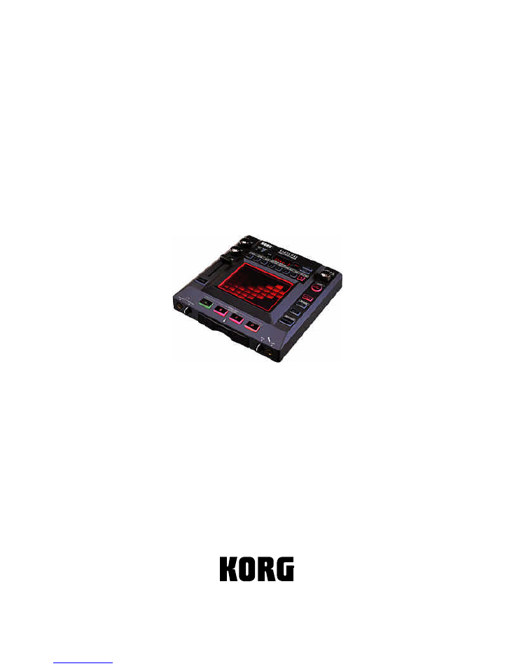
KORG KP3
SERVICE MANUAL
TABLE OF CONTENTS
ASSEMBLY SKETCH (HOOKUP): 2
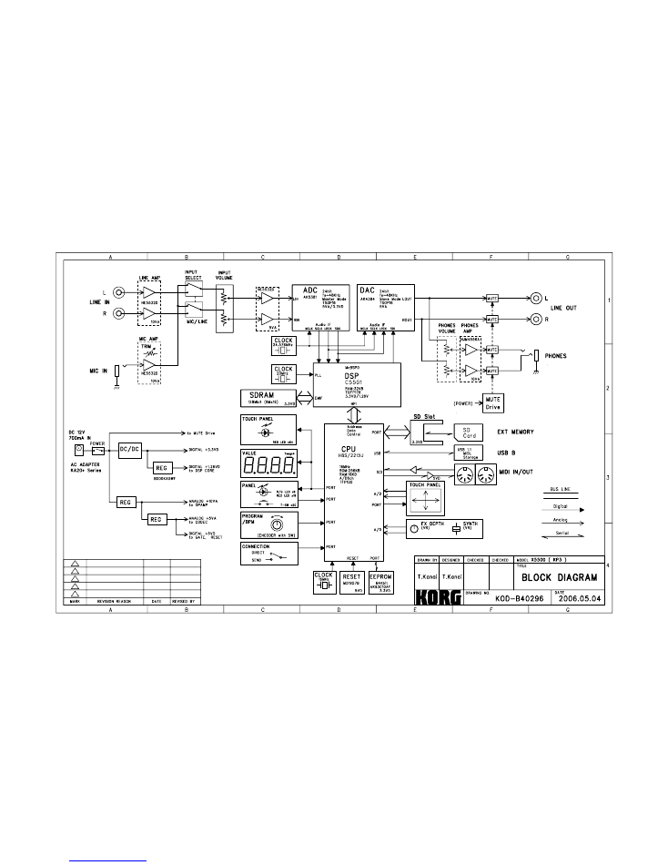
BLOCK DIAGRAM:
3
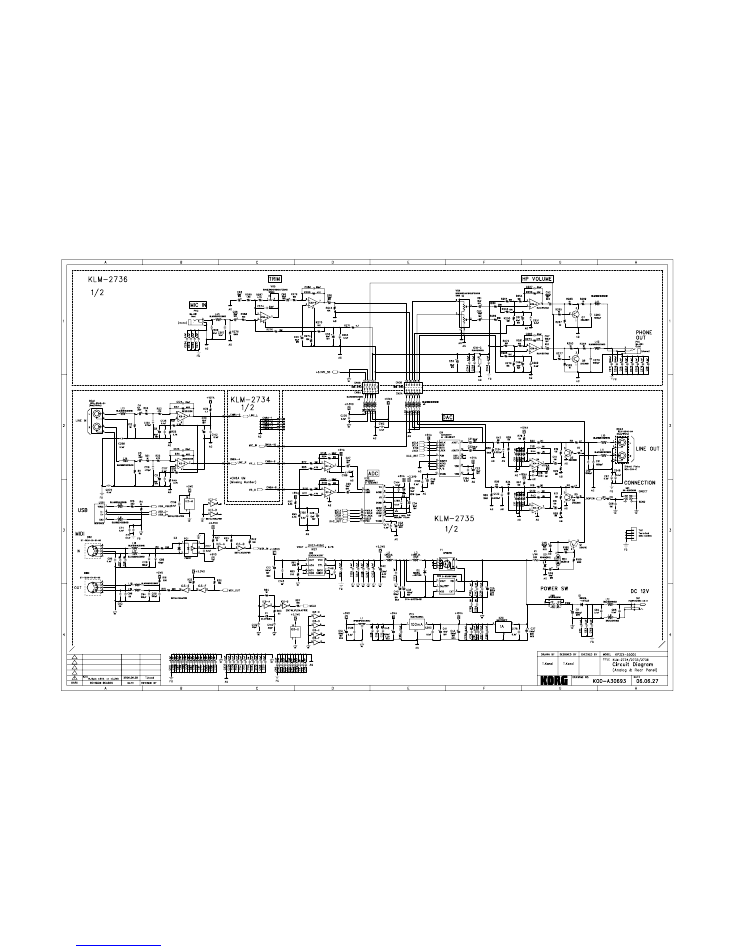
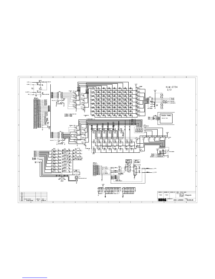
SCHEMATIC DIAGRAM: 4-6
TEST MODE: 7-10
PAD CALIBRATION: 11-12
PARTS LIST: 1
3
-1
4
Issued
Nov.6
, 2006
Ver.
2 Changed P11
Added Pad Cal 3/13/08 - GA
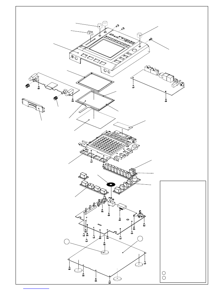
X-5500 Hookup
①
②
③
④
⑤
⑥
⑦
⑩
⑧
⑨
⑪
⑫&⑬
⑭
⑮
⑯
⑰
⑲
⑱
⑳
21
22
①:
UPPER CASE
②:
SLIDER KNOB
③:
VR KNOB
④:
ENCODER KNOB
⑤:
BTB 3BBC 3
×
8
⑥:
PAD FRAME
⑦:
SPONGE SEAL A
⑧:
SPONGE SEAL B
⑨:
TOUCH PANEL
⑩:
VR KNOB(2Color)
⑪:
SD FRAME
⑫:
SUPPORT PLATE
⑬:
SHEET
⑭:
WINDOW
⑮:
LED FRAME
⑯:
RUBBER KEY 1
⑰:
RUBBER KEY 2
⑱:
RUBBER KEY 3
⑲:
RUBBER KEY 4
⑳:
SWITCH MASK
:
URETHANE LEG
:
BOTTOM PLATE
21
22
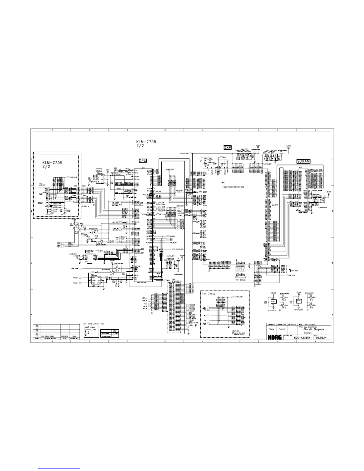
R86 68Ω→33Ωに変更
2006.7.25
T.Kanai
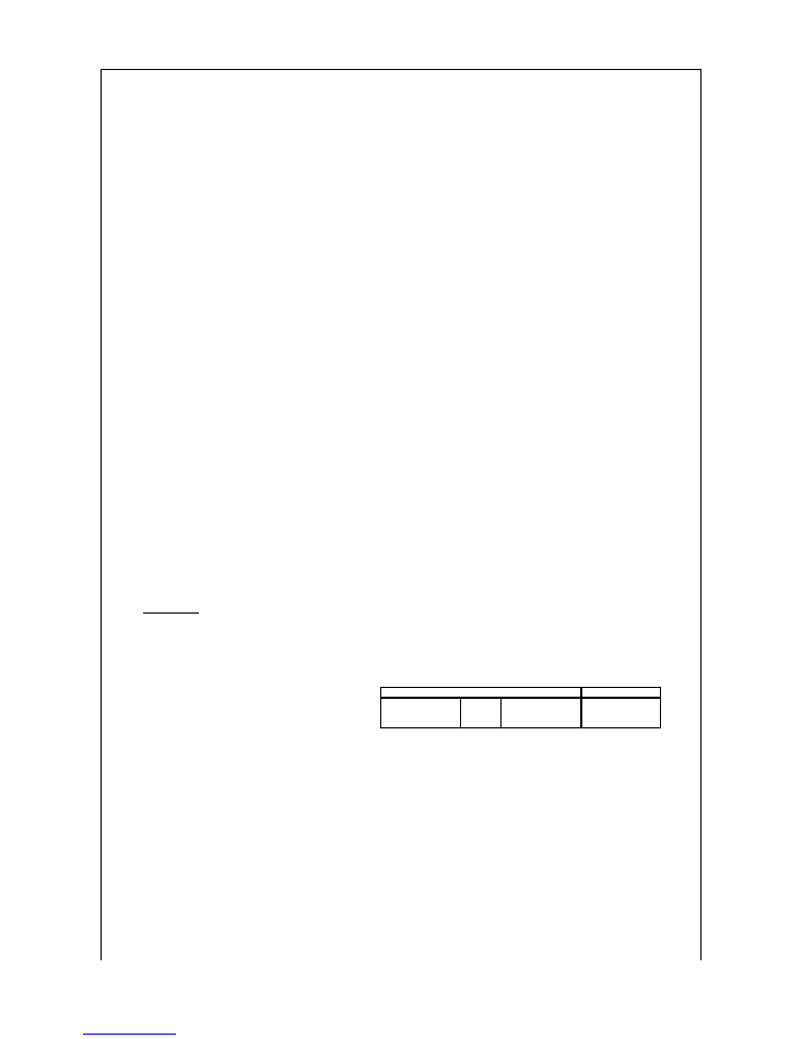
KORG KP3 TEST MODE
2006.8.30 KORG PD3 T.Kanai
How to enter the simple TEST MODE
English by M.Y.
Pushing following switches, and turn
the
power ON.
CONNECTION[SEND] & [7] + [TAP/RANGE]
: Skipping the Audio Loop Back Inspection and the USB check
CONNECTION[SEND] & [5] + [TAP/RANGE]
: Skipping the MIDI Loop Back inspection and the USB check.
Other test modes for repairing
Pushing following switches, and turn
the
power ON.
CONNECTION[SEND] & [1] + [TAP/RANGE]
: Skipping the Audio Measurements and PAD surface inspection
CONNECTION[SEND] & [2] + [TAP/RANGE]
: Audio Measurement only
CONNECTION[SEND] & [3] + [TAP/RANGE]
: PAD all surface inspection only
CONNECTION[SEND] & [4] + [TAP/RANGE]
: Full inspection (Internal and External)
CONNECTION[SEND] & [6] + [TAP/RANGE]
: External inspection
[TAP/RANGE] + [SAMPLING]
: Display of System Version
[1] + [2] + [SAMPLING]
: Load the Preset
[SAMPLING] + [SAMPLE BANK C] + [SAMPLE BANK D]
: IPL Mode
Functions of switches
[TAP/RANGE]
: Step Up (When an error occurred in the internal inspection, retry the inspection.)
[SAMPLE BANK A]
: Step + (Move within the item)
[SAMPLE BANK B]
: Step - (Move within the item)
[SAMPLE BANK C]
: Item Number Up
[SAMPLE BANK D]
: Item Number Down
[SAMPLE BANK A] + [TAP/RANGE]
: When an error occurred in the internal inspection, skip the inspection
Error Code
KP3 displays the Error Code in the LED, when an error occurred in the internal inspection.
4 digits of the LED indicates the error code.
[Er.**]
* (Ten's digit) : Item number (item of the internal inspection)
* (One's digit): Test number( In the internal inspection)
Item
1. DSP IF Check
Notice: When the start-up condition or the forwarding between CPU <-> DSP is NG,
2. DSP - SDRAM Check
KP3 cannot start the test mode, because after the forwarding the Boot code,
3. CPU ROM Check
KP3 moves to the self check sequence (TEST MODE).
4. EEPROM Check
5. Loop Back Check (Audio)
6. MIDI Loop Check
7. Card Check
8. USB Check
*USB check needs a special computer, so skip by [SAMPLE BANK A] + [TAP/RANGE]
when an error occurred in the inspection.
*
Initial Settings
Set the volumes and the switches like followings.
CONNECTION
: SEND
INPUT Select
: LINE
INPUTVR
: MAX
→
Fx Depth
: MIN
→
Slider
: MIN (0)
→
PHONES VR
: MAX
MICTrim:MAX
: MAX
SD Card
(
Protect OFF)
(Caution:) Use the AC Adaptor of KA-20*series
Internal Inspection
1. DSP IF Check
When an error occurred, the inspection stops displaying [Er.11]-[Er.13] in the LED display.
2. DSP SDRAM Check
When "Data Error", the inspection stops displaying [Er.22] or [Er.23] in the LED display.
When "Address Error", the inspection stops displaying [Er.21] in the LED display.
3. CPU ROM Check
When "Checksum Error", the inspection stops displaying [Er.31] in the LED display.
Connection for the automatic inspections
Cable
MIDI OUT
MIDI IN
MIDI cable
LINE OUT L
LINE IN L
RCA cable
LINE OUT R
LINE IN R
RCA cable
4. EEPROM Check
When "Verify Error", the inspection stops displaying [Er.41] in the LED display.
5. OVER LOAD Line Check ( Audio LoopBack )
<<<In the simple TEST MODE, you can skip this.>>>
a: OUTPUT Lch(LINE IN (Rch: GND Level)
Connect the LINE OUT(L) to the LINE IN(L), when the level of the LINE IN(L) is out of the decided range,
the inspection stops displaying [Er.51] in the LED display.
Connect the LINE OUT(L) to the LINE IN(L), when the level of the LINE IN(R) is more than the decided level,
the inspection stops displaying [Er.52] in the LED display.
b: OUTPUT Rch(LINE IN (Lch: GND Level)
Connect the LINE OUT(R) to the LINE IN(R), when the level of the LINE IN(R) is out of the decided range,
the inspection stops displaying [Er.53] in the LED display.
Connect the LINE OUT(R) to the LINE IN(R), when the level of the LINE IN(L) is more than the decided level,
the inspection stops displaying [Er.54] in the LED display.
(Caution) *1 Before the internal inspection, connect LINE OUT(L) to LINE IN(L), LINE OUT( R )to LINE iN ( R ) by two cables.
*2 Set INPUT VOLUME at MAX, INPUT SELECT (toggle) is LINE side.
6. MIDI Loop Check
<<<In the simple TEST MODE, you can skip this.>>>
When KP3 cannot receive the Data, the inspection stops displaying [Er.61] in the LED display.
During receiving the data when KP3 could not receive some data, the inspection stops displaying [Er.62] in the LED display.
When the received data is different value, the inspection stops displaying [Er.63] in the LED display.
(Caution) *3. Connect MIDI IN and MIDI OUT by a MIDI cable, before the internal inspection.
7. Card Check
After [C.Ins] is appeared in the LED display, insert a SD card.
When a SD card is not inserted and KP3 could not detect that a card is not inserted, [Er.71] is displayed in the LED.
After inserted a SD card and remove your hand from the card, then confirm that the card is rocked.
When KP3 could not detect that a SD card is inserted, [Er.72] is displayed in the LED.
When KP3 could not write or read the data, [Er.73] is displayed in the LED.
When the inspection has completed as OK, [C.Pul] is displayed in the LED, then pull out the SD card.
(Caution) *4 Use the SD card as protect OFF.
*5 Do not insert the SD card before [C.Ins] is displayed in the LED.
8. USB Check
<< Skip this inspection>>
* The special computer is needed for this inspection, so skip by [SAMPLE BANK A] + [TAP/RANGE].
* Errors are displayed as [Er.8*], ignore these errors.
9. All LEDs light
a. Confirm that all LEDs light.
All LEDs except followings light. : LEDs(8x8) of PAD, 7segments LED[8888], [SMPL]SW
LED of two colors are followings
.:PEAK, [TAP/RANGE]
、
[SAMPLE BANK A], [SAMPLE BANK B], [SAMPLE BANK C], [SAMPLE BANK D]
Confirm that there is not the uneven brightness, and that there is not slanted LED.
After the confirmation, push [TAP/RANGE] , then the inspection proceeds to 10 External Inspection.
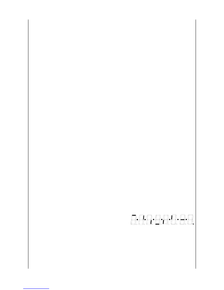
10. 7 Segments LED, segments light one by one.
For each digit, segments light one by one like the right figure.
After confirmation of the four digits, push [TAP/RANGE] SW and proceed
to next inspection.
(Caution) *6. You need all digit's inspection to proceed to the next inspection.
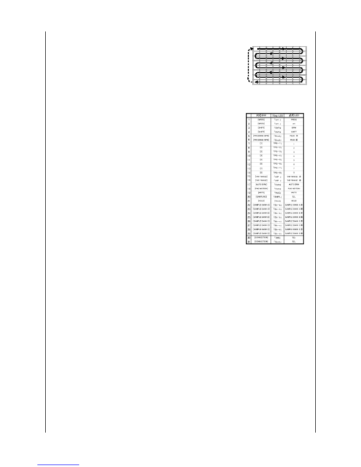
11. PAD LEDs, LEDs light one by one.
LEDs light one by one, from upper left-upper right-next right-next left-
like the right figure.
Push [TAP/RANGE] to proceed to next inspection.
(Caution) *7 You need one cycle of inspection to proceed to the next inspection.
12. Switch & LED Check
*In the 7segments LED, the switch you should push at first is displayed.
{wrt] is displayed in the LED.
*Proceed the inspection as following order.
*When the waiting for pushing the switch, the switch which should be push is displayed in the LED,
and LED lights which is corresponding the switch.
*After switch's inspection, next is inspection of the [CONNECTION]SW.
[dIrE] is displayed in the LED, set [CONNECTION]SW to "DIRECT".
[Send} is displayed in the LED, set {CONNECTION]SW to "SEND"
(Caution) *8 Confirm that the indicated LED lights in the indicated color. (No indication is red.)
*9 When other wrong) switch is pushed or plural switches are pushed, LED blinks.
*10 [SAMPLING]SW has no LED, so it does not light and {SMPL] is displayed in the LED.
*11 [CONNECTION]SW has no corresponding LED, so it is only in the 7 segments LED display.
13. Encoder Check
[Enc.0] is displayed in the LED.
Pull out the knob, adjust the shaft of the Encoder(PROGRAM/BPM) at the start position.
After adjusting, push {TAP/RANGE]SW then [ 0} is displayed in the LED display.
a. Encoder right
Rotate the encorder to the right one cycle.
After one rotation, confirm [ 30] is displayed. Then push [TAP/RANGE] to proceed to next step.
After one rotation, [ -30] is displayed or other display than[ 30] is displayed, it is NG.
During rotation,
[5]LED lights, at 1/4 position
[5],[6] LEDsi light at 2/4 position
[5],[6],[7] LEDs light 3/4 position
When passed even if one click, [5],[6],[7],[8] LEDs turn OFF
[5],[6],[7],[8] LEDs light after one rotation Rotate left and the display is less than 30, the corresponding LED lights.
b. Encoder left
Rotate the encorder to the left one cycle.
After one rotation, confirm [ 30] is displayed. Then push [TAP/RANGE] to proceed to next step.
After one rotation, [ -30] is displayed or other display than[ 30] is displayed, it is NG.
During rotation,
[4]LED lights, at 1/4 position
[4],[3] LEDs light at 2/4 position
[4],[3],[2]LEDs light 3/4 position
When passed even if one click, [4],[3],[2],[1 LEDs turn OFF
[4],[3],[2],[1] LEDs light after one rotation Rotate left and the display is less than 30, the corresponding LED lights.
Confirm that there is no rubbing or feeling of not smooth when rotation.
14. FX DEPTH Check
[FX.dP] is displayed in the LED display.
Rotate FX DEPTH to the left end, all LEDs of [1]-[8] are OFF.
Rotate FX DEPTH to the right, [1], [2], [3], [4], [5], [6], [7], [8] LEDs turn ON (increasing one by one),
and at the right end all LEDs of [1]-[8] turn ON. Rotate to the left, LEDs turn OFF one by one (decreasing).
After finished, inspection proceeds to next.
PROG [WRITE]
→
WRITE [WRITE]
→
BPM [SHIFT]
→
SHIFT [SHIFT]
→
PEAK
赤
[PROGRAM/BPM]
→
PEAK
緑
[PROGRAM/BPM]
→
1 [1]
→
2 [2]
→
3 [3]
→
4 [4]
→
5 [5]
→
6 [6]
→
7 [7]
→
8 [8]
→
TAP/RANGE
赤
[TAP/RANGE]
→
TAP/RANGE
緑
[TAP/RANGE]
→
AUTO BPM [AUTO BPM]
→
PAD MO
SWITCH | 7SEG-LED | LED lights
RED
GREEN
RED
GREEN
R
G
R
G
R
G
R
G

Confirm that there is no rubbing or feeling of not smooth when rotation.
After the confirmation, proceed to next inspection.
15. LEVEL (Slider) Check
[SLdr] is displayed in the LED display.
Push [TAP/RANGE] to start the inspection.
Move LEVEL slider from MIN(lowest)->MAX(highest)->MIN(lowest)
At MIN(lowest) position, all LEDs of [1]-[8] are OFF.
Move to MAX(highest), [1], [2], [3], [4], [5], [6], [7], [8] LEDs turn ON (increasing one by one),
At MAX(highest) position all LEDs of [1]-[8] turn ON.
Move to MIN(lowest), LEDs turn OFF one by one (decreasing).
Confirm that there is no rubbing or feeling of not smooth when moving.
After the confirmation, proceed to next inspection.
16. Touch PAD Check
[Pd.1 ] is displayed in the LED display.
One LED upper left turns ON, push this part by your finger then [P_1 ] is displayed in the LED then remove the finger from the PAD.
The next LED turns ON.
[P2. ] is displayed in the LED display.
4 LEDs of upper left turn ON, push the center of these then [P_2 ] is displayed in the LED. then remove the finger from the PAD.
[P3. ] is displayed in the LED display.
One LED lower right turns ON, push this part by your finger then [P_3 ] is displayed in the LED then remove the finger from the PAD.
After removing the finger from PAD, inspection proceeds to next.
17. Touch PAD Calibration
Complete steps 2 & 3 of "Calibrating the Touch Pad" on the next page; or p
ush [SAMPLE BANK D]
to
skip this item.
18. Inspection of the PAD surface.
After audio measurement, push [SAMPLE BANK D] then [Pd.2 ] is displayed in the LED and start the inspection of the PAD surface.
When you touch the PAD, KP3 sounds.
Stroke slowly all the surface of the PAD and confirm that the frequency of the sound does not change.
When the sound changed to high frequency sound, the inspection is NG
because other part than the part you touch is pushed.
When stroking the PAD, confirm that there is not strange feeling.
Confirm that sound stops when you remove the finger from the PAD.
The inspection is NG when the sound does not stop after removed from the PAD.
Confirm that there are no dusts and etc. on the surface and beneath the PAD.
19.Preload
Move the {CONNECTION]SW to "DIRECT" to the status of waiting for the preload.
[PrLd] is displayed in the LED display, pushing [SAMPLE BANK A] sw and push [TAP/RANGE] to execute the preload.
After finished preload, KP3 restarts in normal operation and [LOAd] in the LED display changes to [FLE.1].
[FLE.1] is not displayed in the LED display after few while the preload is failed.
Calibrating the Touch Pad
Depending on the operating environment, the touch pad segments that light when the
pad is pressed might be out of position. When this happens, the following steps should
be taken to re-calibrate the touch pad.
Please use a plastic pointing device such as a PDA stylus or a gaming device touch pen.
using a sharp or metallic object will risk damaging the touch pad surface.
1.
Turn on the power while pressing the PROGRAM MEMORY 7, PROGRAM
MEMORY 8 and [SAMPLING] buttons.
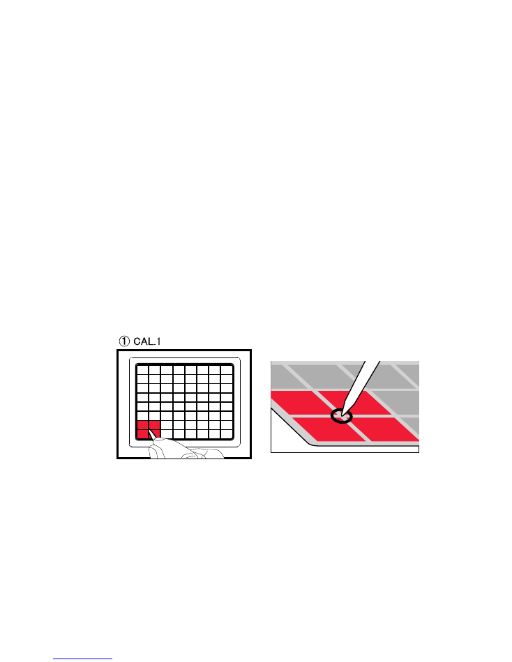
"CAL.1" should appear on the display and the four bottom left touch pad segments
should light up.
2.
Using the pointing device, lightly touch the centre of the four lit segments where
the grid lines cross as shown in the diagram below.
!NOTE! do not move the pointing device from this position while the pad is touched.
After touching this point for a short while, the calibration will move onto the next
step: the next set of four segments will light and the display should read “CAL.2”.
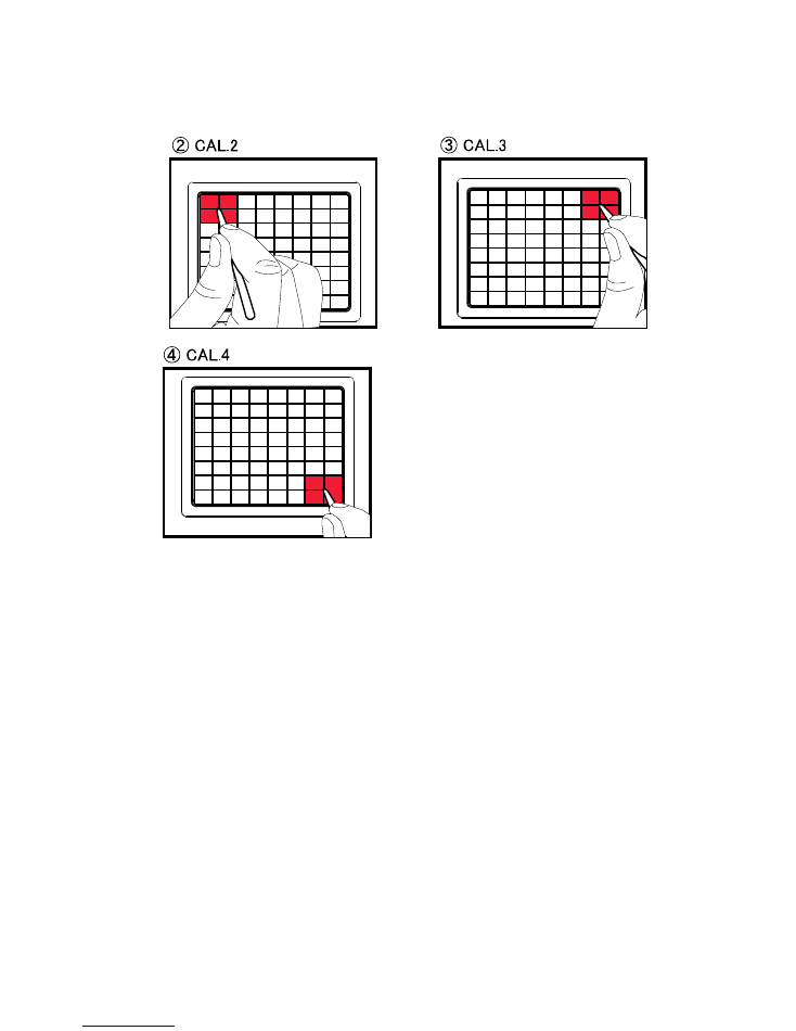
3.
Remove the pointing device from the touch pad and repeat for the next position
indicated by the segment lights.
Complete all four steps as shown in the following diagrams.
4.
After completing the four steps, the touch pad lights will go out and "P.oFF" will be
displayed.
!NOTE! do not turn the power off until "P.oFF" is displayed.
5.
The unit is now re-calibrated. Turn the power off and on as usual and confirm that
the KP3 operates correctly.
1 / 2
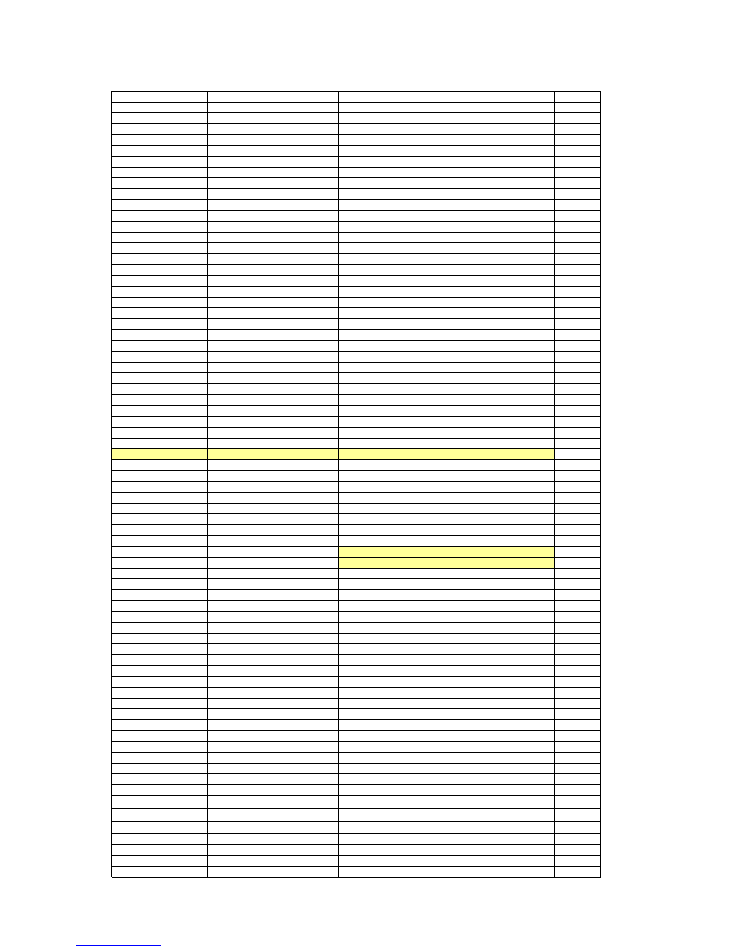
KORG KP3 PARTS LIST
Part Number
Category
Part Name
QTY
510306510001
POWER MOS FET
CPH6316-TL-E (S)
1
510310510502
DOUBLE DIODES
MC2840-T112-1 (S)
1
510310511507
DIODE
RLS-73 TE-11 (S)
22
510310511506
SCHOTTKY DIODE
RB051L-40TE25 (S)
2
510310511001
ZENER DIODE
RD10M-T1B-A (B3) (S)
1
510300510503
TRANSISTOR
2SA812-T1B-A M5-7 M6 RANK(S)
3
510300510502
TRANSISTOR
2SC1623A-T1B AT
1
510300511504
TRANSISTOR
2SC3661-TB-E (S)
4
510300511009
DIGITAL TR
DTC114EKA T146 (TS) (S)
16
510300511015
DIGITAL TR
DTB143EK T146 (S)
16
510312513001
Chip LED
TO-2013BC-MRE (S)
80
510312513009
Chip LED
TO-3227BC-MRMG EE (S)
6
510316521502
SEGMENT LED
TOF-3461BH-B9
1
510646502093
X-5500 LED SPACER E10236-2(D)
1
510324021160
OPAMP
NE5532DR (TS)
3
510320511008
OPAMP
NJM4556AM-TE1-#ZZZB (S)
1
510320515502
Logic IC
SN74LVU04APWR
1
510320516029
Logic IC
SN74LV125APWR (S)
1
510320516013
Logic IC
SN74LV126APWR (S)
1
510320516016
Logic IC
IC SN74LV138ANSR (TS) (S)
2
510320516056
Logic IC
SN74LV574ANSR (S)
2
510320516010
Logic IC
SN74LV05APWR (S)
1
500324023008
IC
S-8520F33MC-BNST2G
1
510320511009
REGULATOR IC
NJM78L05UA-TE2 (TS)(S)
1
510320514025
REGULATOR IC
BA17810FP
1
510320514026
LDO IC
BD00KA5WF
1
500330003700
PHOTO COUPLER
PS9117-F3-A
1
510320512002
RESET IC
M51953BFP#CF1J (S)
1
500324018018
EEPROM
AK93C10AF-E1
1
500320004718
CPU
HD64F2215UTE16V (X5500)
1
510320516070
DSP
TMS320VC5501PGF300
1
500324026004
SDRAM
MT48LC8M16A2P-75:G TR
1
510324019513
A/D Converter
AK5381VT
1
510324038010
D/A Converter
AK4384ET-E2
1
510335520001
CRYSTAL
HC-49US 16MHZ (D)
1
510335520007
CRYSTAL
HC-49US 20.000MHZ (D)
1
510335552008
CRYSTAL
HC-49US 24.576MHZ SS (D)
1
510374524026
SLIDE VR
RA4522F-20-15C1-B5K-0015
1
510370521001
ROTARY ENCODER
RE111F-41B1-15F-15P-05
1
510374524027
ROTARY VR
RV112BCF-40-20A-B10K
1
510374524017
ROTARY VR
RV09ACF-40-20F-B5K-0057
1
510360521510
VR
R0923NOAH1B104FE0061 (D)
1
510360521511
VR
R0925GOAH1B103FE0061 (D)
1
510450520019
DIN JACK
ST-1550-01-S1-60
2
510474520501
USB CONNECTOR
GE813A02 (USB B TYPE) (D)
1
510450520008
PHONE JACK
MJ-081 (PHONE-J MONO GOLD) (D)
1
510450520009
PHONE JACK
MJ-084 (PHONE-J ST GOLD) (D)
1
510450520010
RCA PIN JACK
RCA-204G-04 (D)
2
510450522504
DC JACK
PJCP042100-42-0 (D)
1
510374522002
SLIDE SW
SK-22D06G8 2P2T (D)
1
510374522018
TOGGLE SW
TS-22E01-AC18-NI
1
510374520004
PUSH SW
SPUN192600 (D)
1
510450520011
RCA PIN JACK
SHIELD PLATE RCA-204-E (D)
2
510470521003
HARNESS
HNS-3153 FLATCABLE 5P 2MM (D)
3
510470521005
HARNESS
HNS-3155 6P 2MM BD-IN/HSG (D)
1
510474523003
CONNECTOR
5597-04APB7F (39532044)
1
500474043700
FFC CONNECTOR
XF2M-5015-1A
2
510470521552
FFC
HNS-3647
1
510474510501
CARD CONNECTOR
AXA273021T
1
500415004302
TOUCH PANEL
N010-0517-T902
1
510C33682734
PCB ASS'Y
KLM-2734-KP3 (ASS'Y)
(1)
510C33682735
PCB ASS'Y
KLM-2735/6-KP3 (ASS'Y)
(1)
510640507004
Mechanical Part
X-5500 UPPER CASE KOC-C10259
1
510640506510
Mechanical Part
X-5500 BOTTOM PLATE KOC-C30714
1
510500502531
Mechanical Part
X-5500 RUBBER KEY 1 KOC-E30429
1
510500502532
Mechanical Part
X-5500 RUBBER KEY 2 KOC-E30430
1
510500502533
Mechanical Part
X-5500 RUBBER KEY 3 KOC-E30431
1
510500502534
Mechanical Part
X-5500 RUBBER KEY 4 KOC-E30432
1
510500502535
Mechanical Part
X-5500 ENCORDER KNOB
E30426
1
510646502094
Mechanical Part
X-5500 VR KNOB
KOC-E30427
2
510646502095
Mechanical Part
X-5500 SLIDER KNOB KOC-E30428
1
2 / 2
Part Number
Category
Part Name
QTY
500620040700
Mechanical Part
KNOB P423-90F(X-9100) E40519-1
2
500620018201
Mechanical Part
PSW KNOB (
ユシュツ
) E40224
1
510646502096
Mechanical Part
X-5500 SD FRAME
KOC-E20275
1
510646502099
Mechanical Part
X-5500 LCD FRAME
KOC-E20276
1
510646506504
Mechanical Part
X-5500 SUPORT PLATE KOC-F30119
1
510646506505
Mechanical Part
X-5500 WINDOW
KOC-F41269
1
510646502097
Mechanical Part
X-5500 LED FRAME KOC-E10236-1
1
510500501515
Mechanical Part
X-5500 SWITCH MASK KOC-F41307
1
510500500008
Mechanical Part
X-332CHINA URETHANE-LEG F40709
4
510500501510
Mechanical Part
SHIELD FORM 10X10X60
1
510500501511
Mechanical Part
SHIELD FORM 10X10X12
1
510405540009
AC ADAPTER
KA-201 12V 700mA EIAJ-Plug(100JP)
(1)
510405540010
AC ADAPTER
KA-203 12V 700mA EIAJ-Plug(120US/CN/EX)
(1)
510405540011
AC ADAPTER
KA-209 12V 700mA EIAJ-Plug(230GE/FR/WG)
(1)
510405540012
AC ADAPTER
KA-206 12V 700mA EIAJ-Plug(230UK)
(1)