Full Text Searchable PDF User Manual
KPM III ELECTRONIC SEED MONITOR
QUICK REFERENCE GUIDE
(Phase 2 Software)
KINZE
®
Manufacturing, Inc.
1
IS714 - 6/08
MONITOR KEY FUNCTIONS
Consult Operator & Parts Manual for detailed information.
PHYSICAL KEYS
• Located on R.H. side of console and referred to as F1, F2, F3, F4, F5, F6.
• Keys are referenced in descending order with F1 at the top and F6 at the bottom.
ON/OFF
• Powers the unit on and off.
ESC
• Used as the CANCEL (escape) key.
ENTER
• Confirms or accepts the highlighted selection.
ROTARY ENCODER/KNOB
• Turn knob clockwise to scroll down or counterclockwise to scroll up
• Press knob to enter selection.
AV (AUDIO/VIDEO) Key
• Set alarm volume.
• Adjust the contrast.
• Adjust backlighting of the LCD display.
ACK (ACKNOWLEDGE) Key
• Used to silence (acknowledge) the warning alarm when various error conditions occur.
NOTE: Alarms can be viewed by pressing the STATUS key.
ARROW KEYS
• UP arrow key is used to move up.
• DOWN arrow key is used to move down.
• LEFT arrow key is used to move to the left.
• RIGHT arrow key is used to move to the right.
ESC
ACK
KPM III ELECTRONIC SEED MONITOR
QUICK REFERENCE GUIDE
(Phase 2 Software)
REPROGRAMMING/CONNECTING SENSORS
NOTE: All sensors (including the seed tubes w/sensors, radar, magnetic distance and shaft rotation
sensors) must be unplugged from the harness and/or console and the monitor must be OFF.
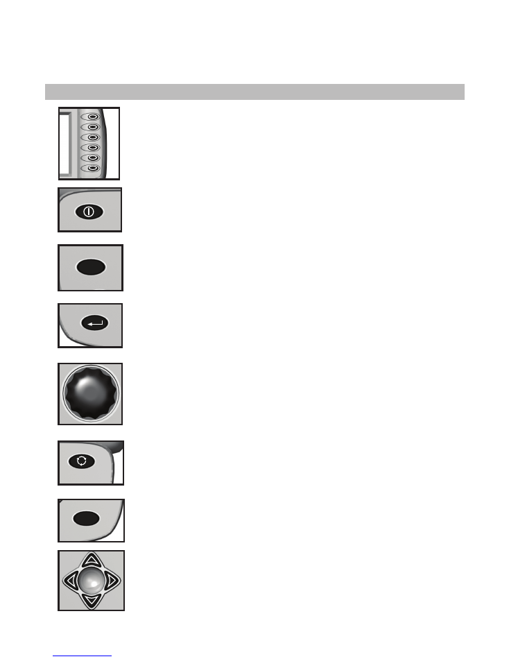
Turn monitor ON. Monitor automatically displays “No Sensors Detected” screen. Press the
knob or ENTER key to select OK.
“KINZE Planter Configuration” screen will appear, verify all information is correct. Turn the
knob or press the arrows keys to advance to OK. Press the knob or ENTER key.
Attach the planter harness into the KPM III. Do NOT connect any of the sensors to the
planter harness, with [Auto Detect] selected press the INSTALL key (F1).
Plug in the first sensor (row 1), working from left to right and rear to front (if applicable).
When a sensor is connected to the planter harness wait for the monitor to acknowledge
with two beeps.
Continue connecting seed sensors along with shaft rotation sensors or speed sensors.
Progress will reflect on the LCD screen.
When all of the sensors are installed press the F1 key.
NOTE: Consult Operator & Parts Manual for detailed information.
REPLACING SEED SENSOR(S)
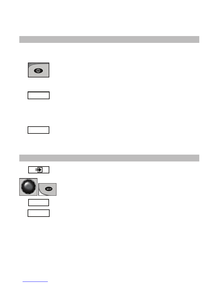
Press F6 key until the “Mode Selection” screen appears.
Select “Setup Mode’’ by turning the knob or press the UP or DOWN arrow keys.
Press the knob or ENTER key to display the highlighted item.
Select “Sensor Setup’’ by turning the knob or press the UP or DOWN arrow keys.
Press the knob or ENTER key to display the highlighted item.
Highlight the faulty sensor and press the REMOVE key and unplug sensor. Plug in
new sensor and press INSTALL key.
Repeat above procedure for each faulty sensor being replaced.
NOTE: Highlighting a sensor and pressing VIEW gives additional information when
troubleshooting a problem. If a faulty sensor has been ignored it may be highlighted
in the list of sensors, press REVIVE. The monitor will try to communicate with the
sensor. If successful “OK’’ will appear next to the sensor.
Consult Operator & Parts Manual for detailed information.
KINZE
®
Manufacturing, Inc.
2
IS714 - 6/08
Setup Mode
Install
Remove
Ignore
Revive
Done
Rear Row 1 OK
Rear Row 2 OK
Rear Row 3
OK
Rear Row 4 OK
Rear Row 5 OK
Rear Row 6 OK
Rear Row 7 OK
Rear Row 8
OK
Rear Row 9 OK
Rear Row 10
OK
Rear Row 11 OK
View
Sensor Setup
[Auto Detect]
[Seed Sensors]
Setup Mode
Install
Remove
Ignore
Done
Rear Row 1 OK
Rear Row 2 OK
Rear Row 3
OK
Rear Row 4 OK
Rear Row 5 OK
Rear Row 6 OK
Rear Row 7 OK
Rear Row 8
OK
Rear Row 9 OK
Rear Row 10
OK
Rear Row 11 OK
View
Sensor Setup
[Auto Detect]
[Seed Sensors]
F1
F2
MPH
Avg
Pop
0
0.0
1 2 3 4 5 6 7 8 9 10 11 12
1 2 3 4 5 6 7 8 9 10 11 12
120
110
100
90
80
70
60
%
120
110
100
90
80
70
60
%
Contrast
Alarm
Front Row 1
Muxbus Comm lost contact
F1
Ignore this sensor
F2
Keep trying this sensor
Status
Plant
About
Kinze Planter Monitor III
Lifetime Area:
Please select the operating mode for the
planter monitor or the action to perform.
Effective row spacing: 15.0
0.00
1. Setup Mode
2. Acre Count Mode
3. Disable Interplant (Enabled now)
4. Data logging disabled
5. Test Mode
Setup Mode
Install
Remove
Ignore
Revive
Done
Rear Row 1 OK
Rear Row 2 OK
Rear Row 3
OK
Rear Row 4 OK
Rear Row 5 OK
Rear Row 7 OK
Rear Row 8
OK
Rear Row 9 OK
Rear Row 10
OK
Rear Row 11 OK
View
Sensor Setup
[Auto Detect]
[Seed Sensors]
Seed Rate Alarm
Rear Row 6 OK
KPM III ELECTRONIC SEED MONITOR
QUICK REFERENCE GUIDE
(Phase 2 Software)
PROGRAMMING/CLEARING THE MONITOR
KINZE
®
Manufacturing, Inc.
3
IS714 - 6/08
Consult Operator & Parts Manual for detailed information.
CHANGING VOLUME/CONTRAST/BACKLIGHTING
• Press the AV key (once for volume, twice for contrast or three times for backlighing).
• Turn knob or use the LEFT or RIGHT arrow keys to adjust.
• Press the knob or ENTER key to save and exit.
SPEED SENSOR CALIBRATION/PROGRAMMING
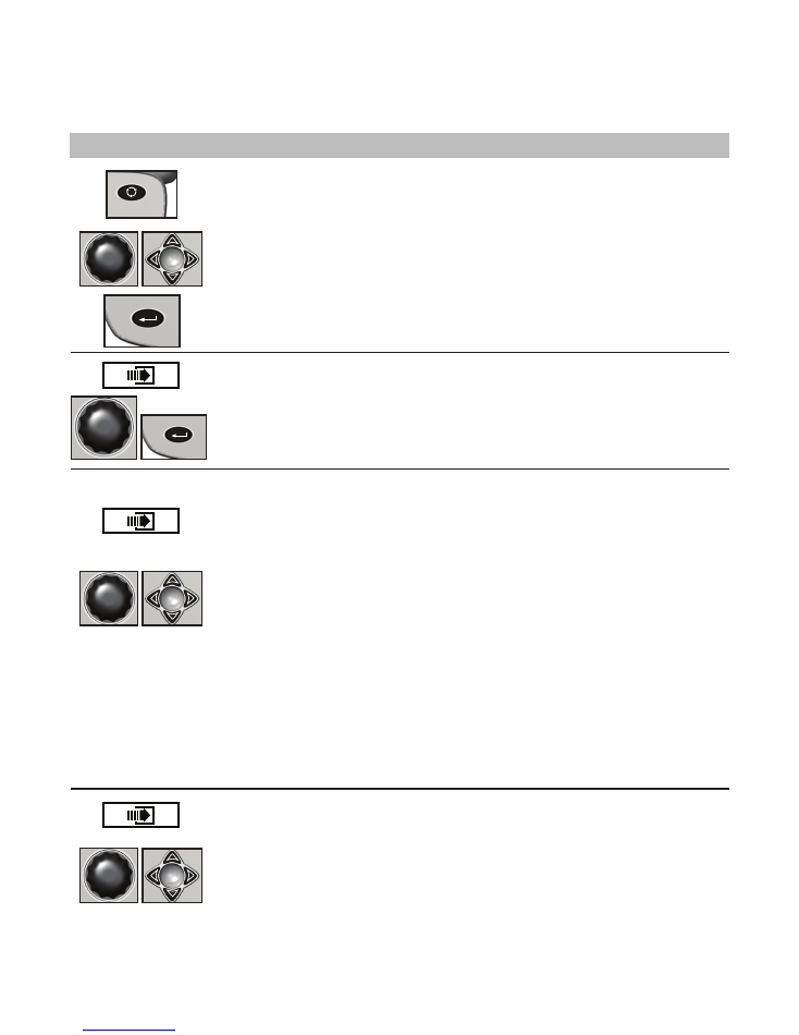
• Press F6 key until “Mode Selection’’ screen appears and select “Setup Mode’’ and press the
knob or ENTER key.
• Press F6 key to advance to “Speed Sensor Calibration’’.
• Pull tractor to starting point and then press knob or ENTER key. Travel 330 ft. (100m) and
stop tractor even with measured mark.
• Select “Tractor Calibration Done’’ and then press the knob or ENTER key.
PROGRAMMING UNITS
• Press F6 key until “Mode Selection’’ screen appears and then select “Setup Mode’’ by turning
the knob or using the UP or DOWN arrow keys. Press the knob or ENTER key to display the
highlighted item.
• Select “General Settings’’ by turning the knob or press the UP or DOWN arrow keys. Press
the knob or the ENTER key to display the highlighted item.
• Advance to “Row Spacing’’ field by turning the knob or using the UP or DOWN arrow keys.
A drop down number pad will appear. Turn the knob or use the arrow keys to highlight the
correct value then press the knob to select the number, for numbers containing more than
one digit select one digit at a time. When the desired quantity is displayed, press the ENTER
key.
• Advance to “Units of Measure” field by turning the knob or using the UP or DOWN arrow
keys.
• Press the knob or ENTER key, a drop down menu will appear. Select either “English’’ or
“Metric’’ from the drop down menu by turning the knob or using the UP or DOWN arrow keys.
Press the knob or ENTER key to make selection.
• Advance to “Area Counters” field by turning the knob or using the UP or DOWN arrow keys.
Select “Confirm each enable/disable” press the knob or ENTER key.
• Select either OK or Cancel as appropriate.
NOTE: The narrowest row spacing the planter is equipped to plant should be entered for
“Row Spacing”. Example: 12 Row 30" with Interplant row spacing would be set to 15".
CLEARING AREA COUNTERS
• Press F6 key until “Area Management’’ screen appears.
• Turn knob or press the UP or DOWN arrow keys to highlight the desired “Area Counter’’
• Press the CLEAR key.
• Confirm that the area counter is to be cleared by selecting either OK or Cancel.
Status
Plant
About
Kinze Planter Monitor III
Lifetime Area:
Please select the operating mode for the
planter monitor or the action to perform.
Effective row spacing: 15.0
0.00
1. Setup Mode
2. Acre Count Mode
3. Disable Interplant (Enabled now)
4. Data logging disabled
5. Test Mode
Status
Plant
About
Kinze Planter Monitor III
Lifetime Area:
Please select the operating mode for the
planter monitor or the action to perform.
Effective row spacing: 15.0
0.00
1. Setup Mode
2. Acre Count Mode
3. Disable Interplant (Enabled now)
4. Data logging disabled
5. Test Mode
Status
Plant
About
Kinze Planter Monitor III
Lifetime Area:
Please select the operating mode for the
planter monitor or the action to perform.
Effective row spacing: 15.0
0.00
1. Setup Mode
2. Acre Count Mode
3. Disable Interplant (Enabled now)
4. Data logging disabled
5. Test Mode
KPM III ELECTRONIC SEED MONITOR
QUICK REFERENCE GUIDE
(Phase 2 Software)
KINZE
®
Manufacturing, Inc.
4
IS714 - 6/08
Consult Operator & Parts Manual for detailed information.
ROW-BY-ROW ALARM LEVEL SETTING
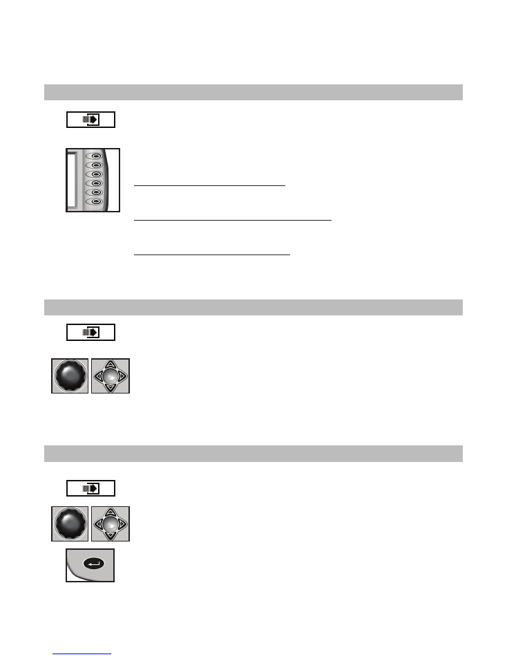
Press F6 key until “Mode Selection’’ screen appears.
Select “Setup Mode’’ by turning the knob or press the DOWN arrow key.
Press the knob or ENTER key to display the highlighted item.
Select “Row Unit Alarm Levels’’ by turning the knob or press the DOWN arrow key.
Press the knob or ENTER key to display the highlighted item.
To set alarm thresholds for whole planter:
- Select “Whole Planter’’.
- Press the key next to the desired threshold.
To set alarm thresholds for all the rows in one section:
- Select “Rear Front’’ or “Left Right’’ section.
- Press the key next to the desired threshold.
To set alarm thresholds for individual rows:
- Select the desired row.
- Press the key next to the desired threshold.
Press the knob or ENTER key to save.
AREA MANAGEMENT
Press F6 key until “Area Management’’ screen appears.
Highlight the desired “Area Counter’’ by turning the knob or press the UP or DOWN arrow
keys.
Press the ENTER key to ENABLE or DISABLE.
NOTE:
“
Total Area Counter
”
can never be disabled.
ENABLE/DISABLE INTERPLANT
Press F6 key until the “Mode Selection” screen appears.
Turn the knob or press UP or DOWN arrow keys to highlight “Disable/Enable Interplant”.
Press the knob or ENTER key to “Disable” or “Enable” Interplant.
To verify selection, the row spacing is displayed on the bottom of the screen.
Status
Plant
About
Kinze Planter Monitor III
Lifetime Area:
Please select the operating mode for the
planter monitor or the action to perform.
Effective row spacing: 15.0
0.00
1. Setup Mode
2. Acre Count Mode
3. Disable Interplant (Enabled now)
4. Data logging disabled
5. Test Mode
Status
Plant
About
Kinze Planter Monitor III
Lifetime Area:
Please select the operating mode for the
planter monitor or the action to perform.
Effective row spacing: 15.0
0.00
1. Setup Mode
2. Acre Count Mode
3. Disable Interplant (Enabled now)
4. Data logging disabled
5. Test Mode
Status
Plant
About
Kinze Planter Monitor III
Lifetime Area:
Please select the operating mode for the
planter monitor or the action to perform.
Effective row spacing: 15.0
0.00
1. Setup Mode
2. Acre Count Mode
3. Disable Interplant (Enabled now)
4. Data logging disabled
5. Test Mode