Full Text Searchable PDF User Manual

INSTRUCTION
آ
آ
آ
آ
Industrial
Sewing
Machines
First published : July 1997
Second edition : October 2000
No. 000079
PX302-4W
PX302-5W

INTRODUCTION
INTRODUCTION
INTRODUCTION
INTRODUCTION
Thank you for your purchasing Kansai Special's PX Series.
Read and study this instruction manual carefully before beginning any of the
procedures and save it for later use.
1. This instruction manual describes adjustments and maintenance procedures on this
machine.
2. Before starting the machine, check to make sure the pulley cover, safety cover, etc.
are secured.
3. Before adjusting, cleaning, threading the machine or replacing the needle, be sure
to turn off the power.
4. Never start the machine with no oil in the reservoir.
5. Refer to the parts list as well as this instruction manual before performing
preventive maintenance.
6. The contents described in this instruction manual are subject to change without
notice.

CONTENTS
CONTENTS
CONTENTS
CONTENTS
1. NEEDLES & THREADING THE MACHINE
1-1 Needles
・・・・・・・・・・・・・・・・・・・・・・・・・・・・・・・・・・・・・・・・・・・・・・・・・・・・・・・・
1
1-2 Replacing the needle
・・・・・・・・・・・・・・・・・・・・・・・・・・・・・・・・・・・・・・・・・・・・
1
1-3 To thread the machine
・・・・・・・・・・・・・・・・・・・・・・・・・・・・・・・・・・・・・・・・・・
1
2. MACHINE SPEED
2-1 Machine speed & direction in which the machine pulley runs
・・・・・・・
2
2-2 Motor & belt
・・・・・・・・・・・・・・・・・・・・・・・・・・・・・・・・・・・・・・・・・・・・・・・・・・・・
2
3. LUBRICATION
3-1 Oil
・・・・・・・・・・・・・・・・・・・・・・・・・・・・・・・・・・・・・・・・・・・・・・・・・・・・・・・・・・・・・
3
3-2 To fill the machine with oil
・・・・・・・・・・・・・・・・・・・・・・・・・・・・・・・・・・・・・・
3
3-3 Replacing the oil and the filter element
・・・・・・・・・・・・・・・・・・・・・・・・・・・
3
4. SEWING MACHINE INSTALLATION
4-1 Cutting the machine table
・・・・・・・・・・・・・・・・・・・・・・・・・・・・・・・・・・・・・・・
4
4-2 To install the machine
・・・・・・・・・・・・・・・・・・・・・・・・・・・・・・・・・・・・・・・・・・・
5
5. TIMING OF THE LOOPER TO THE NEEDLE
5-1 Needle height
・・・・・・・・・・・・・・・・・・・・・・・・・・・・・・・・・・・・・・・・・・・・・・・・・・
5
5-2 Needle drop and needle side stroke
・・・・・・・・・・・・・・・・・・・・・・・・・・・・・・・
6
5-3 To install the looper
・・・・・・・・・・・・・・・・・・・・・・・・・・・・・・・・・・・・・・・・・・・・・
6
5-4 Eccentric for adjusting the looper left to right
・・・・・・・・・・・・・・・・・・・・・
7
5-5 Position of the looper rocker
・・・・・・・・・・・・・・・・・・・・・・・・・・・・・・・・・・・・・
7
5-6 Looper left-to-right movement
・・・・・・・・・・・・・・・・・・・・・・・・・・・・・・・・・・・
8
5-7 Looper/needle front-to-back relationship
・・・・・・・・・・・・・・・・・・・・・・・・・・
8
5-8 Looper setting distance
・・・・・・・・・・・・・・・・・・・・・・・・・・・・・・・・・・・・・・・・・・
8
5-9 Adjusting the looper back spring
・・・・・・・・・・・・・・・・・・・・・・・・・・・・・・・・・
9
6. ADJUSTING THE NEEDLE GUARD
・・・・・・・・・・・・・・・・・・・・・・・・・
9
7. ADJUSTING THE FEED DOG & STITCH LENGTH
7-1 Feed dog height
・・・・・・・・・・・・・・・・・・・・・・・・・・・・・・・・・・・・・・・・・・・・・・・・・
9
7-2 Stitch length
・・・・・・・・・・・・・・・・・・・・・・・・・・・・・・・・・・・・・・・・・・・・・・・・・・
10
7-3 Differential feed ratio
・・・・・・・・・・・・・・・・・・・・・・・・・・・・・・・・・・・・・・・・・・
10
8. ADJUSTING THE PRESSER FOOT
8-1 Presser foot pressure
・・・・・・・・・・・・・・・・・・・・・・・・・・・・・・・・・・・・・・・・・・・
10
8-2 Position of the presser foot and foot lift
・・・・・・・・・・・・・・・・・・・・・・・・・・
11
9. ADJUSTING THE STITCH FORMATION
9-1 Adjusting the looper thread eyelets
・・・・・・・・・・・・・・・・・・・・・・・・・・・・・・
11
9-2 Position of the looper thread take-up
・・・・・・・・・・・・・・・・・・・・・・・・・・・・
12
9-3 Adjusting the needle thread guard
・・・・・・・・・・・・・・・・・・・・・・・・・・・・・・
12
10. CLEANING THE MACHINE
・・・・・・・・・・・・・・・・・・・・・・・・・・・・・・・・・
12

1
م€گ
1
م€‘
NEEDLES & THREADING THE MACHINE
1111----1 Needles
1 Needles
1 Needles
1 Needles
UO163 of Schmetz or Organ
Select the proper needle for the fabric and thread.
< Comparison table of needle sizes >
Schmetz
UY163GAS Nm65 Nm70 Nm75 Nm80 Nm90
Organ UO163
#9
#10
#11
#12
#14
1111----2 Replacing the needle
2 Replacing the needle
2 Replacing the needle
2 Replacing the needle
When replacing the needle, check the needle carefully
to see that the scarf is turned to the rear of the
machine (see the illustration).
1111----3 To thread the machine
3 To thread the machine
3 To thread the machine
3 To thread the machine
Thread the machine correctly by referring to the illustration below. Incorrect
threading may cause skip stitching, thread breakage and/or uneven stitch formation.
< Note >
When replacing the needle, be sure to turn off the
machine. A clutch motor continues running for a while
after the machine is turned off. Therefore keep on
pressing the pedal until the machine stops.
A
,
B ... Needle threads
C
,
D ... Looper threads
2
م€گ
2
م€‘
MACHINE SPEED
2222----1 Machine speed & direction in which the machine pulley runs
1 Machine speed & direction in which the machine pulley runs
1 Machine speed & direction in which the machine pulley runs
1 Machine speed & direction in which the machine pulley runs
Maximum speed : 3,500 rpm
Standard speed : 3,000 rpm
To extend machine life, run the machine
approximately 15~20% below the maximum speed
for the first 200 hours of operation (approx. 1
month). Then run the machine at the standard
speed.
The machine pulley turns counterclockwise as
seen from the end of the machine pulley (see the
illustration).
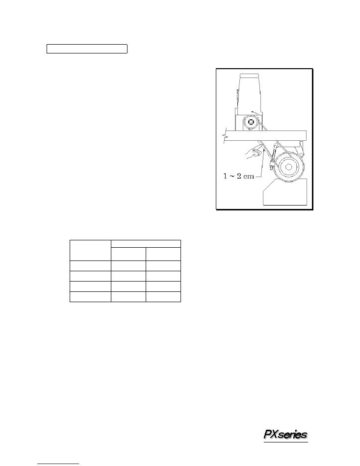
2222----2 Motor & belt
2 Motor & belt
2 Motor & belt
2 Motor & belt
Motor : 3-phase, 2-pole, 400W clutch motor
Belt
: M type V belt
Select the proper motor pulley according to the
machine speed (refer to the motor pulley outer
diameter on the table below). Adjust the position
of the motor by pressing the finger onto the middle
of the belt so that 1~2cm deflection can be
achieved (see the illustration).
< Motor pulley selection table >
Machine speed (SPM)
Motor pulley
outer diameter
(mm)
50Hz 60Hz
60 2500
2950
70 2900
3450
80 3300
(3900)
90 (3700)
(4400)
3
م€گ
3
م€‘
LUBRICATION
3333----1 Oil
1 Oil
1 Oil
1 Oil
Use Kansai Special’s genuine oil
(Part No. 28-611)
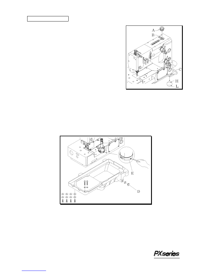
3333----2 To fill the machine with oil
2 To fill the machine with oil
2 To fill the machine with oil
2 To fill the machine with oil
Remove oil plug A. Fill the machine with oil until
the oil level is at the top line (see H in the
illustration) on oil gauge C.
After the first lubrication, add oil so that the oil
level will be between H and L.
After filling the machine with oil, tighten plug A
and run the machine to check the oil is splashing
from oil pipe outlet B.
3333----3 Replacing the oil and the filter element
3 Replacing the oil and the filter element
3 Replacing the oil and the filter element
3 Replacing the oil and the filter element
To extend machine life, be sure to replace the oil after the first 250 hours of operation.
To replace the oil, follow the procedures below.
1. Remove the V belt from the motor pulley and then remove the machine from the
table.
2. Remove screw D and then drain the oil.
Be careful not to stain V belt with the oil.
3. After draining the oil, be sure to tighten screw D.
4. Fill the machine with oil by referring to 3-2 shown above.
If filter element E is contaminated, proper oiling may not be performed.
Clean the filter element every six months. If just a little or no oil flows out from the
nozzle with the proper amount of oil in the machine, check the filter element.
To clean the filter element, remove oil reservoir.
4
م€گ
4
م€‘
SEWING MACHINE INSTALLATION
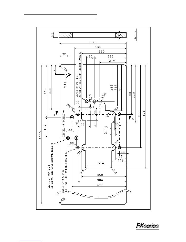
4444----1 Cutting the machine table
1 Cutting the machine table
1 Cutting the machine table
1 Cutting the machine table
5
4444----2
2
2
2 To install the machine
To install the machine
To install the machine
To install the machine
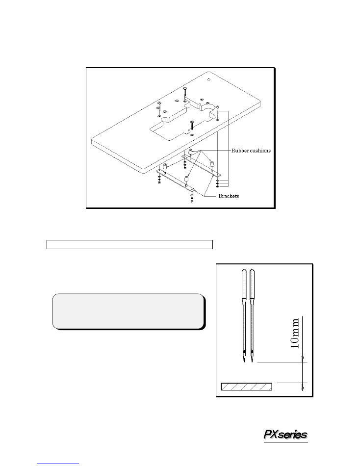
Install the brackets on the underside of the table board (see the illustration below).
Fit the rubber cushions onto the brackets.
Mount the machine head on the rubber cushions correctly.
م€گ
5
م€‘
TIMING OF THE LOOPER TO THE NEEDLE
5555----1
1
1
1 Needle height
Needle height
Needle height
Needle height
When the needle bar is at the top of its stroke, there
should be a distance of approximately 10mm from
the top surface of the needle plate to the point of
the needle. Adjustment is made by loosening
screws A.
< Note >
After the above adjustment is made, check to make
sure each needle drops correctly into the center of
each needle drop hole.
<
<
<
<
M
M
M
M odel
odel
odel
odel
ï¼ڑ
ï¼ڑ
ï¼ڑ
ï¼ڑ
302
302
302
302 ----4W, 302
4W, 302
4W, 302
4W, 302 ----5W
5W
5W
5W
ï¼
ï¼
ï¼
ï¼
6
5555----2
2
2
2 Needle drop and needle side stroke
Needle drop and needle side stroke
Needle drop and needle side stroke
Needle drop and needle side stroke
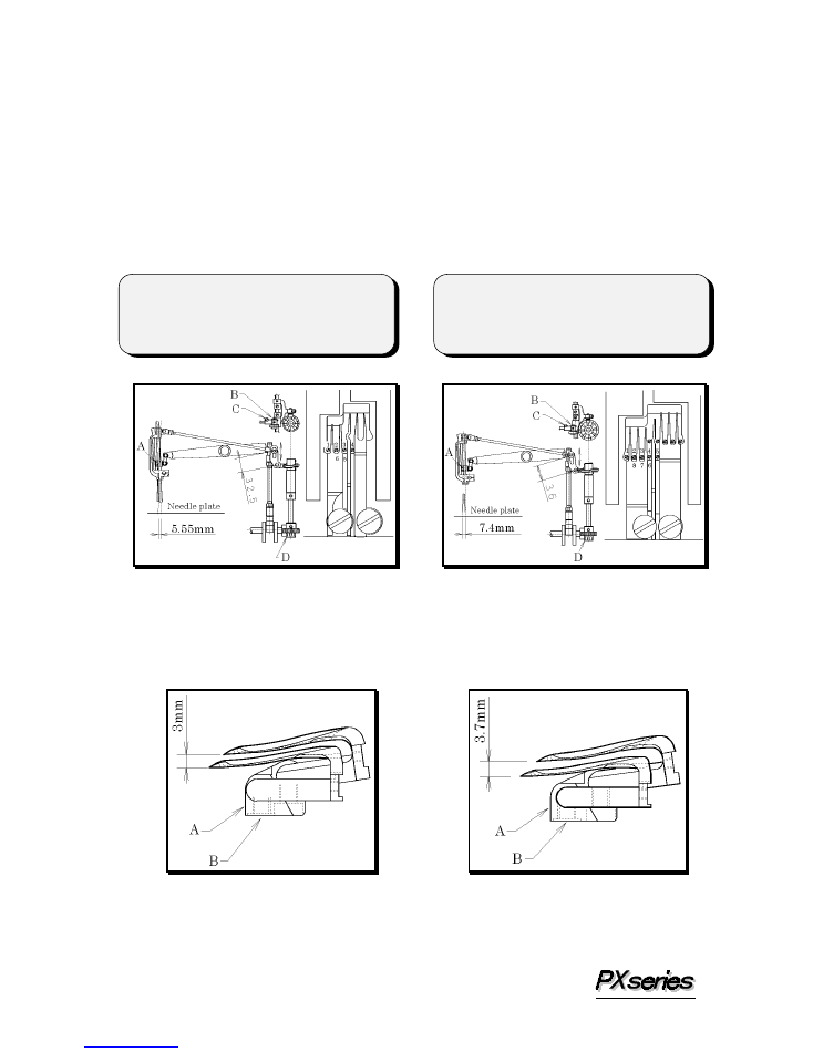
The needle side stroke on this machine is 5.55mm (302-4W) and 7.4mm (302-5W).
To increase the stroke, loosen screw B and move it up in the slot. To decrease the stroke,
loosen screw B and move it down in the slot. The point of the needle should be centered
left to right between fingers of the needle plate when the needle drops to the needle plate.
Adjustment is made by loosening screw C. The needle side stroke movement should
start when the point of the needle moves up from the top surface of the needle plate.
The needle side stroke movement should stop when the point of the needle reaches the top
surface of the needle plate. This timing adjustment is made by worm gear D. To adjust
the position of the needle drop, loosen screws A and turn the needle bar as required.
5555----3333 To install the looper
To install the looper
To install the looper
To install the looper
To set the angle and height of the looper, insert the looper fully into looper holder A and
tighten screw B.
< Note >
Position of the needle drop 1, 2, 3, 4, 5 from
the left side, 5 is the extreme right end. 5,
6, 7, 8, 1 from the right side
< Note >
Position of the needle drop 1, 2, 3, 4 from
the left side, 4 is the extreme right end.
4, 5, 6, 1 from the right side
<
<
<
<
M
M
M
M odel
odel
odel
odel
ï¼ڑ
ï¼ڑ
ï¼ڑ
ï¼ڑ
302
302
302
302 ----4W
4W
4W
4W
ï¼
ï¼
ï¼
ï¼
<
<
<
<
M
M
M
M odel
odel
odel
odel
ï¼ڑ
ï¼ڑ
ï¼ڑ
ï¼ڑ
333302
02
02
02 ----5W
5W
5W
5W
ï¼
ï¼
ï¼
ï¼
<
<
<
<
M
M
M
M odel
odel
odel
odel
ï¼ڑ
ï¼ڑ
ï¼ڑ
ï¼ڑ
302
302
302
302 ----4W
4W
4W
4W
ï¼
ï¼
ï¼
ï¼
<
<
<
<
M
M
M
M odel
odel
odel
odel
ï¼ڑ
ï¼ڑ
ï¼ڑ
ï¼ڑ
302
302
302
302 ----5W
5W
5W
5W
ï¼
ï¼
ï¼
ï¼
7
5555----4 Eccentric for adjusting the looper left to right
4 Eccentric for adjusting the looper left to right
4 Eccentric for adjusting the looper left to right
4 Eccentric for adjusting the looper left to right
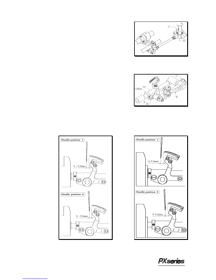
To adjust the position of the eccentric, loosen screws D.
Align the screw which comes second in the turning
direction of the eccentric with the mark on the shaft.
Then tighten screws D temporarily. Then make a
fine adjustment so that the looper shaft can reach the
extreme right end of its travel while the needle is at
the bottom of its stroke with position 4. After this
adjustment, tighten the screws securely. For
PX302-5W, adjust each looper shaft to come the same
position while the needle is at the bottom of its stroke with position 3 and position 7.
5555----5 Position of the looper rocker
5 Position of the looper rocker
5 Position of the looper rocker
5 Position of the looper rocker
The setting distances of the looper with the needle at
position 4 and position 1 should be equal (5.5mm) (For
PX302-5W, the needle at position 1 and position 5) (see
5-2). To achieve this adjustment, loosen screw A to
loosen the collar. Loosen screws B and C.
Then adjust looper rocker D and lever E.
â– آ
Example
If the setting distance with the needle at position 1 is 5mm and the setting distance with
the needle at position 4 is 6mm, move looper rocker D approximately 1mm to right.
After the adjustment is made, tighten screws B and C securely. Then tighten screw A
with the collar fitted onto looper rocker D.
<
<
<
<
M
M
M
M odel
odel
odel
odel
ï¼ڑ
ï¼ڑ
ï¼ڑ
ï¼ڑ
302
302
302
302 ----4W
4W
4W
4W
ï¼
ï¼
ï¼
ï¼
<
<
<
<
M
M
M
M odel
odel
odel
odel
ï¼ڑ
ï¼ڑ
ï¼ڑ
ï¼ڑ
302
302
302
302 ----5W
5W
5W
5W
ï¼
ï¼
ï¼
ï¼
8
5555----6 Looper left
6 Looper left
6 Looper left
6 Looper left----to
to
to
to----right movement
right movement
right movement
right movement
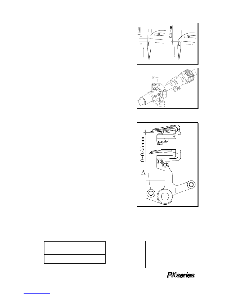
This adjustment should be made when the needle is
at position 1 (see 5-2). When the point of the
looper, moving to the left, has reached the left side
of the needle, it should be 1mm above the top of the
needle's eye. When the point of the looper, moving
to the right, has reached the left side of the needle,
it should be 0.2mm above the top of the needle's
eye.
The looper moves 0.8mm faster than the needle (see
the illustration on the right).
For PX302-5W when the needle is at position 2.
â–
Adjustment is made by loosening three screws F.
After the adjustment, tighten these three screws
equally.
5555----7 Looper/needle front
7 Looper/needle front
7 Looper/needle front
7 Looper/needle front----to
to
to
to----back relationship
back relationship
back relationship
back relationship
Adjust when the needle is at position 3 or 5 (see
5-2).
When the point of the looper is at the center of the
needle, there should be a clearance of 0mm between
the needle and the looper.
Adjustment is made by loosening screw A.
5555----8 Looper setting distance
8 Looper setting distance
8 Looper setting distance
8 Looper setting distance
Check the looper setting distance by referring to the table below.
If the looper setting distance is not correct, perform 5-4, 5-5 procedure again.
Needle position
Setting distance
(mm)
1, 4
5.5
2, 6
4.7
3, 5
5.8
<
<
<
<
M
M
M
M odel
odel
odel
odel
ï¼ڑ
ï¼ڑ
ï¼ڑ
ï¼ڑ
302
302
302
302 ----4W
4W
4W
4W
ï¼
ï¼
ï¼
ï¼
<
<
<
<
M
M
M
M odel
odel
odel
odel
ï¼ڑ
ï¼ڑ
ï¼ڑ
ï¼ڑ
302
302
302
302 ----5W
5W
5W
5W
ï¼
ï¼
ï¼
ï¼
Needle position
Setting distance
(mm)
1, 5
5.5
2, 8
4.2
3, 7
4.8
4, 6
6
9
5555----9 Adjusting the looper back spring
9 Adjusting the looper back spring
9 Adjusting the looper back spring
9 Adjusting the looper back spring
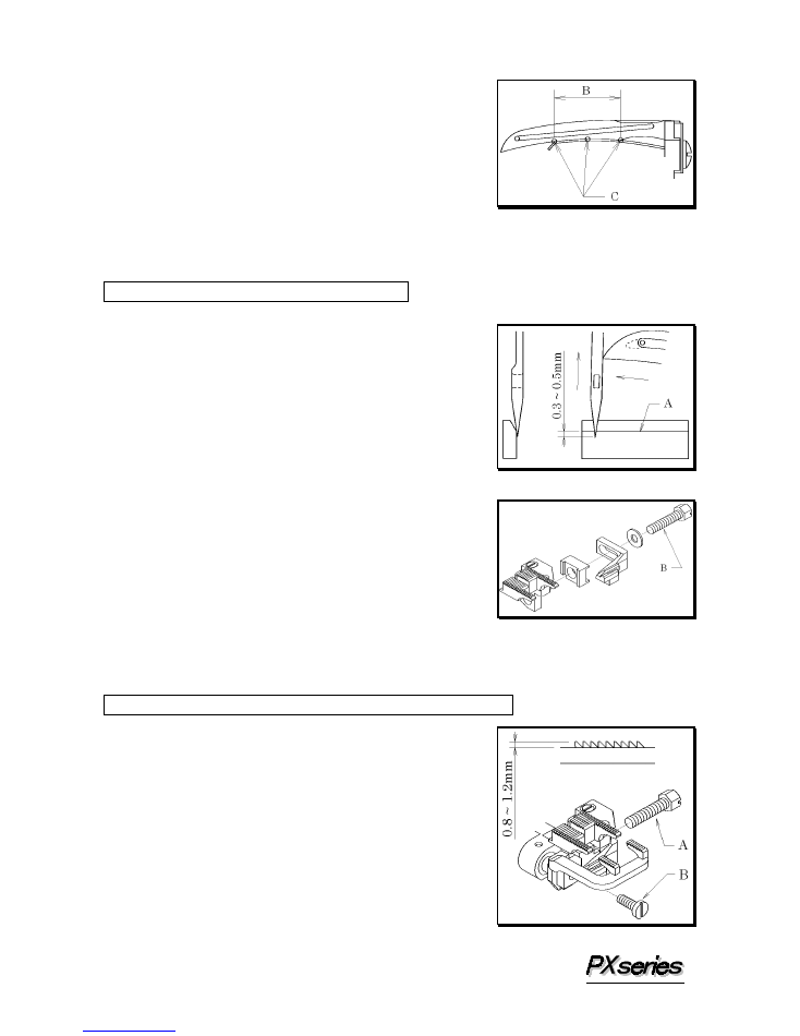
It is the best that the surface of the spring touches the
looper closely within the range of B.
Check to see if the surface of the spring touches the
looper closely at least on points C within the range of
B.
Spun thread #60 should be removed from the spring at
approximately 80~100g of tension.
م€گ
6
م€‘
ADJUSTING THE NEEDLE GUARD
This adjustment should be made when the needle is at
position 4 (see 5-2). When the point of the looper,
moving to the left, has reached the right side of the
needle, line A on the needle guard should be
0.3~0.5mm above the point of the needle (see the
illustration on the right). Then the needle must
slightly touch the needle guard. Adjustment is made
by loosening screw B.
م€گ
7
م€‘
ADJUSTING THE FEED DOG & STITCH LENGTH
7777----1 Feed dog height
1 Feed dog height
1 Feed dog height
1 Feed dog height
When the feed dog is at the top of its stroke, the feed
dog teeth should be 0.8~1.2mm above the top surface
of the needle plate. Adjustment is made by loosening
screws A and B.
10
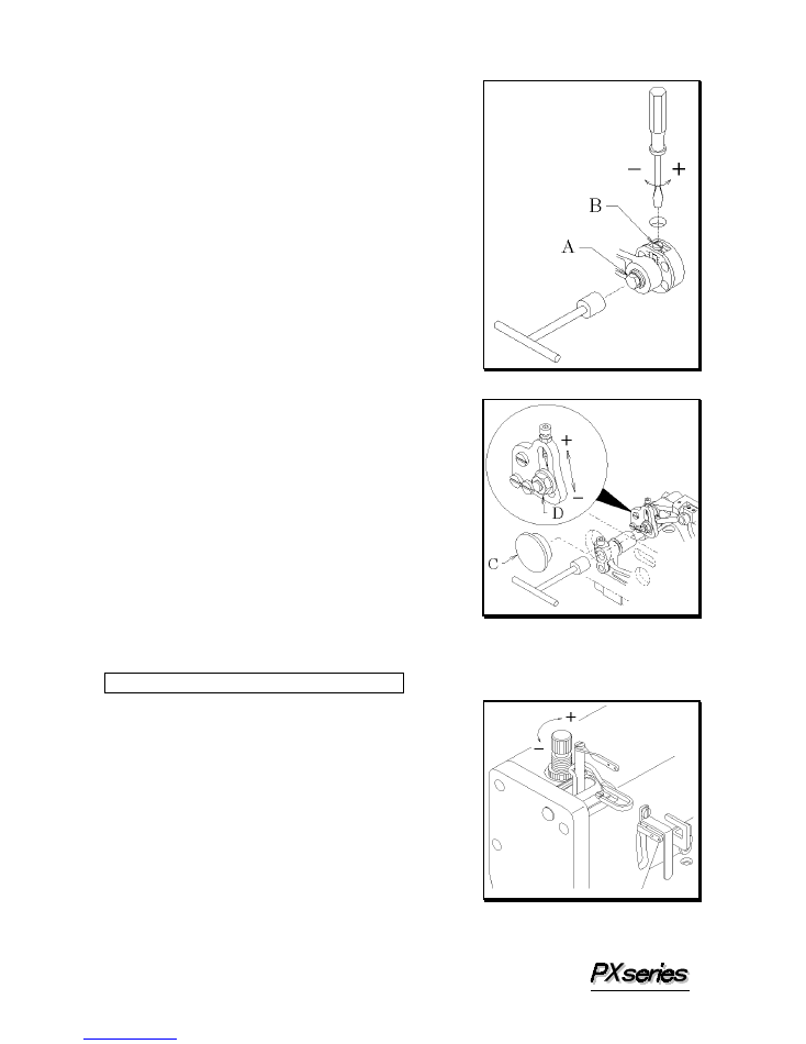
7777----2 Stitch length
2 Stitch length
2 Stitch length
2 Stitch length
Loosen bolt A with a 9.5mm T-wrench.
Then turn screw B as required.
To decrease the stitch length, turn it clockwise.
To increase the stitch length, turn it
counterclockwise (see the illustration on the right).
7777----3 Differential feed ratio
3 Differential feed ratio
3 Differential feed ratio
3 Differential feed ratio
Remove rubber plug C. Loosen nut D.
To increase the differential feed ratio, move up the
nut. To decrease the differential feed ratio, move
down the nut.
م€گ
8
م€‘
ADJUSTING THE PRESSER FOOT
8888----1 Presser foot pressure
1 Presser foot pressure
1 Presser foot pressure
1 Presser foot pressure
The presser foot pressure should be as light as
possible, yet be sufficient to feed the fabric and
produce uniform stitches. To increase the presser
foot pressure, turn the adjusting knob clockwise
(see the illustration on the right).
11
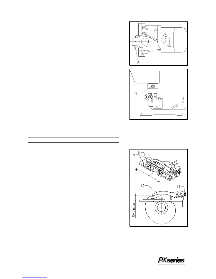
8888----2 Position of the presser foot and foot lift
2 Position of the presser foot and foot lift
2 Position of the presser foot and foot lift
2 Position of the presser foot and foot lift
The presser foot should not touch the needle.
Adjustment is made by loosening screw A and then
moving the presser foot to the right or left.
â– آ
Foot lift
Fit the collar onto the bushing with the presser foot
9mm above the top surface of the needle plate.
Then tighten screw B.
م€گ
9
م€‘
ADJUSTING THE STITCH FORMATION
9999----1 Adjusting the looper thread eyelets
1 Adjusting the looper thread eyelets
1 Adjusting the looper thread eyelets
1 Adjusting the looper thread eyelets
Align the eyes on the looper thread eyelets A with
the center line of the shaft. Adjust looper thread
eyelets A according to sewing conditions such as the
fabric or thread to be used by loosening screws B.
To increase the amount of the thread to be supplied,
move the eyelets backward. To decrease the
amount of the thread to be supplied, move the
eyelets frontward. Thread guide C should be
6~7mm above the guide plate. Adjustment is
made by loosening screw D.
12
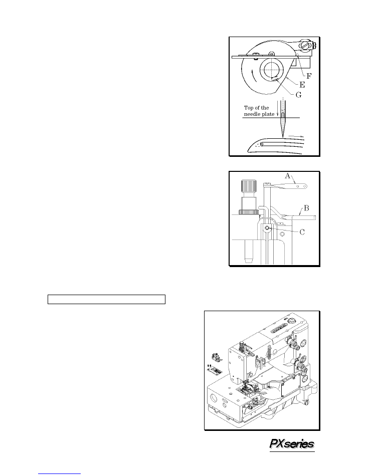
9999----2 Position of the looper thread take
2 Position of the looper thread take
2 Position of the looper thread take
2 Position of the looper thread take----up
up
up
up
When the bottom of the needle's eye has reached the
top surface of the needle plate while the needle is
descending, the looper thread taken up by looper
thread take-up E should be removed from the looper
thread take-up at point F. Adjustment is made by
screw G.
9999----3 Adjusting the needle thread guard
3 Adjusting the needle thread guard
3 Adjusting the needle thread guard
3 Adjusting the needle thread guard
With the needle bar at the bottom of its stroke, the
centers of eyes on needle bar thread eyelet A should be
level with the top surface of needle thread guard B.
Adjustment is made by screw C.
To tighten the needle thread, move up needle bar
thread eyelet A. To loosen the needle thread, move
down needle bar thread eyelet A.
م€گ
10
م€‘
CLEANING THE MACHINE
At the end of each day, remove the presser
foot and the needle plate and then clean the
slots of the needle plate and the area around
the feed dogs.