Full Text Searchable PDF User Manual
Interflex Datensysteme GmbH
1/13
Thank you for choosing a product from Interflex. With this product, you have purchased a reliable device for
access control.
1.1 Scope of delivery
IF-80x Outdoor terminal (slave)
I/O controller board for controlling locking devices
Material for fastening
8-pin terminal strip
Blue wire for grounding the back panel
Mortise lock
Plastic strips for sealing the mortise lock
Adhesive tape for mounting the I/O controller board
Please check the completeness and condition of the
shipment upon receipt.
1.2 CE conformity
The device complies with the requirements of the respective EU guidelines (CE conformity).
Modifications to the device are not permitted.
All information contained in this documentation is accurate at the time of printing. All specifications are
subject to change without notice.
The product brand names and trademarks specified in this documentation are protected by commercial and
patent laws.
1.3 Shielded cables
To ensure malfunction-free operation, we recommend the use of shielded bus cables.
Operation is also possible with unshielded cables. In case of transmission problems, you will have to
examine the reasons in each individual case. Where necessary, a shielded cable should be used for the
connection of the respective devices.
1.4 Intended use
The device is used for reading RFID credentials, e.g. in access control systems, and also for controlling
locking devices. Any other use is not in accordance with the intended purpose and is therefore not permitted.
1.5 Function
Slave terminals of series IF-80x Outdoor are used for:
controlling the access of people who identify themselves via an RFID credential before entering a
security zone.
controlling and monitoring locking devices that prevent uncontrolled (physical) access to security zones.
writing NetworkOnCard access rights. The data is used for identification at offline devices, e.g. electronic
door fittings.
95-10330 V2017-07-24
IF-80x Outdoor Slave Terminal

Interflex Datensysteme GmbH
2/13
The terminals can be operated on terminal controllers or master terminals with the
following controller software versions (minimum requirements):
IF-105x = Version 5.12.4.C2
IF-107x = Version 5.12.3
IF-407x = Version 7.12.3.
1.6 Function of the IF-80x outdoor terminal
Terminals of the IF-80x Outdoor series are part of an access control system. They are preferably installed
directly next to locking devices. They are generally connected to a master terminal, access manager or
terminal controller via an RS485 data cable. These terminals are designed for controlling the access of
persons, who identify themselves with RFID credentials, as well as for controlling and monitoring locking
devices.
1.7 Storage
The device has to be stored in a dry place.
2 Assembly and Installation
Please carry out the following steps in sequence:
Install all cables.
Mount the IF-80x Outdoor terminal.
Make the electrical connections and switch on the power.
Adjust the reader.
Set the hardware address.
Put the terminal into operation and test its functions.
Interflex Datensysteme GmbH
3/13
3 Installation
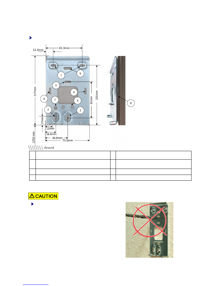
3.1 Mounting the IF-80x outdoor terminal
Recommendation:
Install the terminal at a height of approx. 125 cm (distance from floor to bottom edge
of the terminal).
1 Mounting holes
5 Vertical mounting option with DIN appliance case
2 Alternative mounting hole for wall-mounted cable
inserted from the bottom
6 Mounting holes for US standard
3 Cable gland
7 Hole for adjusting the reader
4 Horizontal mounting option with DIN appliance case 8 Foam rubber
3.2 Important points to note regarding the mounting
Please observe the following when mounting the terminal:
Do not make any changes to the back panel.
Fastening elements in other places can collide with the circuit
board.
Interflex Datensysteme GmbH
4/13
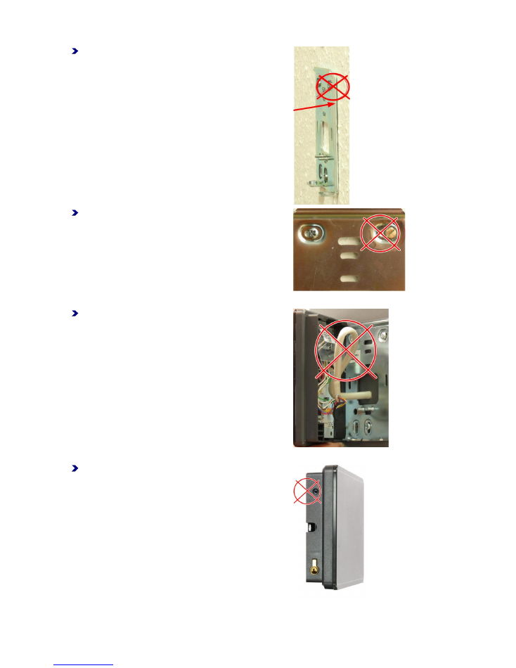
Check for any unevenness in the panel.
The back panel of the device must be level and flush with the
wall.
Mechanical stresses can damage the device.
Use only the original screws and do not use any
washers.
Screws placed too high can cause collisions with other
components and damage the device.
Ensure short cable routing.
Cable loops can damage the device due to mechanical
stresses.
Tighten the screw only slightly or leave it out.
Tightening the screw too tightly can result in mechanical
stresses which can damage the device.
Interflex Datensysteme GmbH
5/13
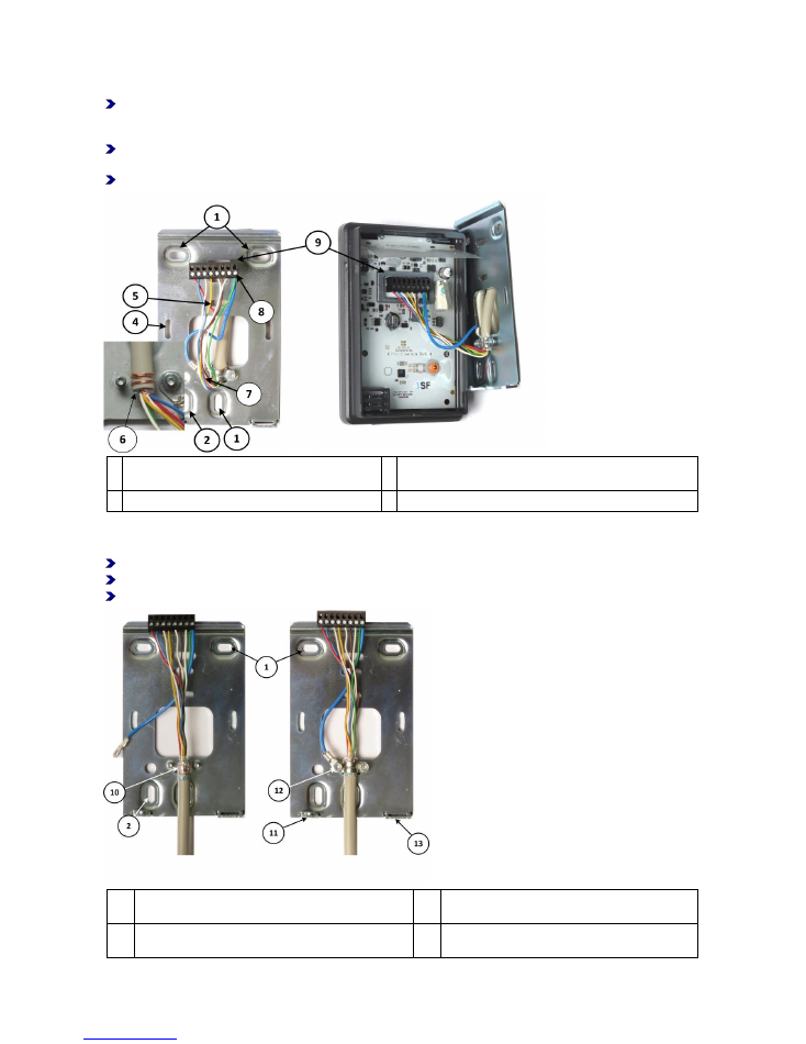
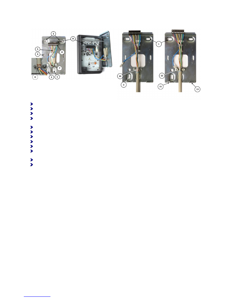
3.3 Fastening the back panel of the housing using an appliance case
Using a level, fasten the back panel of the housing by installing the 3 screws included in delivery in the
holes marked (1). If the cable is to be inserted from the bottom, use mounting hole (2) instead of the
bottom mounting hole (1).
Depending on how the appliance case is installed, you can additionally secure the back panel of the
housing by installing screws in the two horizontal (4) or vertical (5) holes.
For further steps, please refer to: Attaching the IF-800 Outdoor/IF-801 Terminal.
6 This is how the drain wire is wrapped around the
insulation.
8 The blue wire and the PE wire from the I/O controller board
are connected to terminal 8 on the terminal strip.
7 The blue wire is connected to the strain relief.
9 Terminal strip
3.4 Fastening the back panel of the housing with cable feed from the bottom
Using a level, screw in the back panel of the housing by installing 2 screws in the holes marked (1).
In addition, secure the back panel of the housing by installing a screw in the bottom left hole (2).
For further steps, please refer to: Attaching the IF-800 Outdoor/IF-801 Terminal
10 The drain wire must have an electrical connection to
the back panel of the housing.
12 The cable lug of the blue wire is connected to the
strain relief.
11 Lug for fastening the wall reader with the M2x6 mm
screw
13 Lug for mortise lock
Interflex Datensysteme GmbH
6/13
4 Electrical Connections
Avoid damaging the device by:
establishing electrical connections only when no voltage is applied.
changing the position of jumpers or DIP switches only when no voltage is applied.
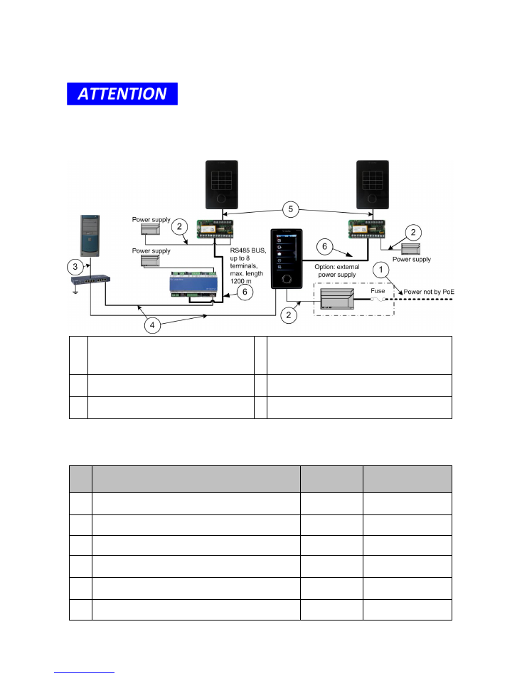
4.1 Installation overview
1
Power supply to mounting rail power supply unit
(41-10106)
4 Ethernet data cable from switch to controller/master
terminal Cable length maximum 100 m. Power is
supplied to the master terminal shown here via PoE or
from an external power supply unit.
2
Power supply to I/O controller board
5 Data cable from I/O controller board to IF-80x Outdoor
terminal
3
Patch cable from computer to switch or hub
6 RS-485 data cable from controller/master terminal to I/O
controller board
Please refer to the table "
Function of Cables and Cable Types
" for detailed information on the cable
lengths, cable types and their diameters.
4.1.1 Cable functions and cable types
Cable Function
Max. Length
Recommended Cable
Type
1
230 VAC power supply to 20 VAC, 1.5 A power transformer
(order no. 41-10106)
NYM 3 x 1.5 mm²
2
Extra low voltage cable
J-Y(ST) Y 4x2x 0.6 mm
3
Ethernet/patch cable from server to switch/hub
max. 100 m
Category 5
4
Ethernet/patch cable from switch/hub to controller/master
terminal
max. 100 m
Category 5
5
Shielded cable from IF-80x Outdoor terminal to
controller/master terminal
max. 100 m
J-Y(ST) Y 4x2x 0.6 mm
6
RS-485 bus cable
max. 1200 m
J-Y(ST) Y 4x2x 0.6 mm
Interflex Datensysteme GmbH
7/13
4.2 Wiring: Step-by-step procedure
Strip approx. 8 cm of the data cable.
Wrap the drain wire (6) around the end of the insulation of the data cable.
Feed the connection cable through the strain relief.
Install the strain relief in such a way that the end of the insulation with the drain wire is electrically
connected to the back panel of the housing (10).
Clamp the blue wire under a nut of the strain relief (12).
Now, connect all of the cables coming from the I/O controller board to the terminal strip of the terminal.
Then, connect the blue wire from the back panel of the housing to the PE terminal.
Plug the terminal strip into the terminal.
Hook in the terminal at the top and press it down until it rests against the wall.
Screw down the terminal on the bottom left side (11) using the M2 x 6 mm countersunk screw included in
delivery.
Insert the mortise lock on the bottom right side and lock the terminal (13).
Use the enclosed plastic strips to seal the mortise lock.

Interflex Datensysteme GmbH
8/13
4.3 Wiring overview
1 IF-80x Outdoor terminal
5 Circuit example: Control of an actuator (door opener).
The actuator may only be operated with max. 30 V and
2 A.
2 I/O controller board
6 Circuit example: Connection of both inputs.
3 Circuit example: Power supply
7 Address switch on the I/O controller board
4 Circuit example: RS485 connection. The spur line may
not be longer than max. 100 m.
Bridges:
Br. 1:
When one I/O controller board is used, bridge 1 is always plugged in.
If a second I/O controller board is used, remove bridge 1 on the second I/O controller board.
Br. 2
: Bridge 2 is used to set the switching contacts of the NO/NC relay.
Br. 3
: Instead of bridge 3, an anti-tamper switch can be connected.
Interflex Datensysteme GmbH
9/13
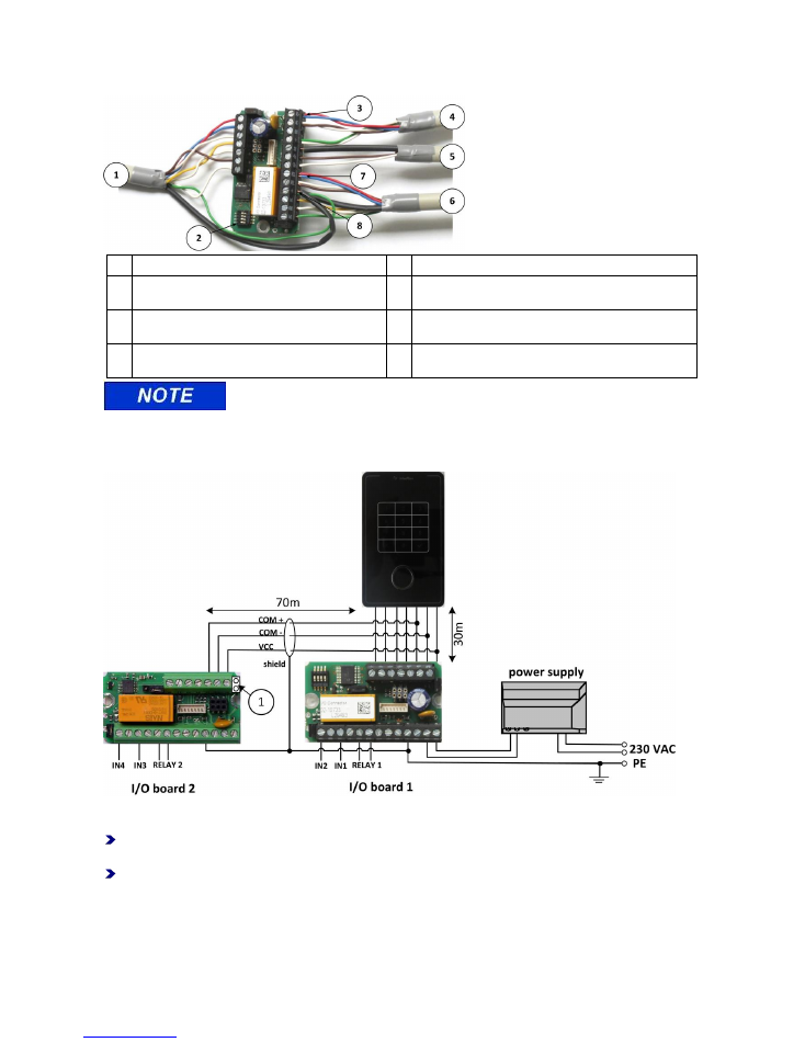
4.4 Connecting the I/O controller board
1
Cable to IF-80x Outdoor terminal
5
RS485 data cable
2
Address switch
6
Control line with 2 floating inputs and 1 relay output.
Max. switching power: 30 V, 2 A
3
Here, the power supply is connected with one line
pair each.
7
Relay output. Here, the cable is connected with one line
pair each.
4
Cable to power supply. Connection voltage: 18 to
max. 24 V AC/DC
8
Functional grounding and shield are connected to a
terminal together.
Since the cable run to the IF-80x Outdoor terminal is usually very long, we
recommend connecting the power supply and the relay contact with one cable pair each.
4.5 Connecting a further I/O controller board
If more than two inputs or more than one relay are required, you can connect a second I/O controller board
(order no. 75-700-0141).
Remove jumper Br.1 on the second I/O controller board.
Please keep in mind that the total length of the COM cable is limited to a maximum of 100 m.
Reduce the length of the COM cable, if necessary, to ensure that the total length of 100 m is not
exceeded.
Example:
The IF-80x Outdoor terminal is connected to I/O controller board 1 by a 30-meter-long cable. The cable for
the connection of I/O controller board 2 may not be longer than 70 m.
Interflex Datensysteme GmbH
10/13
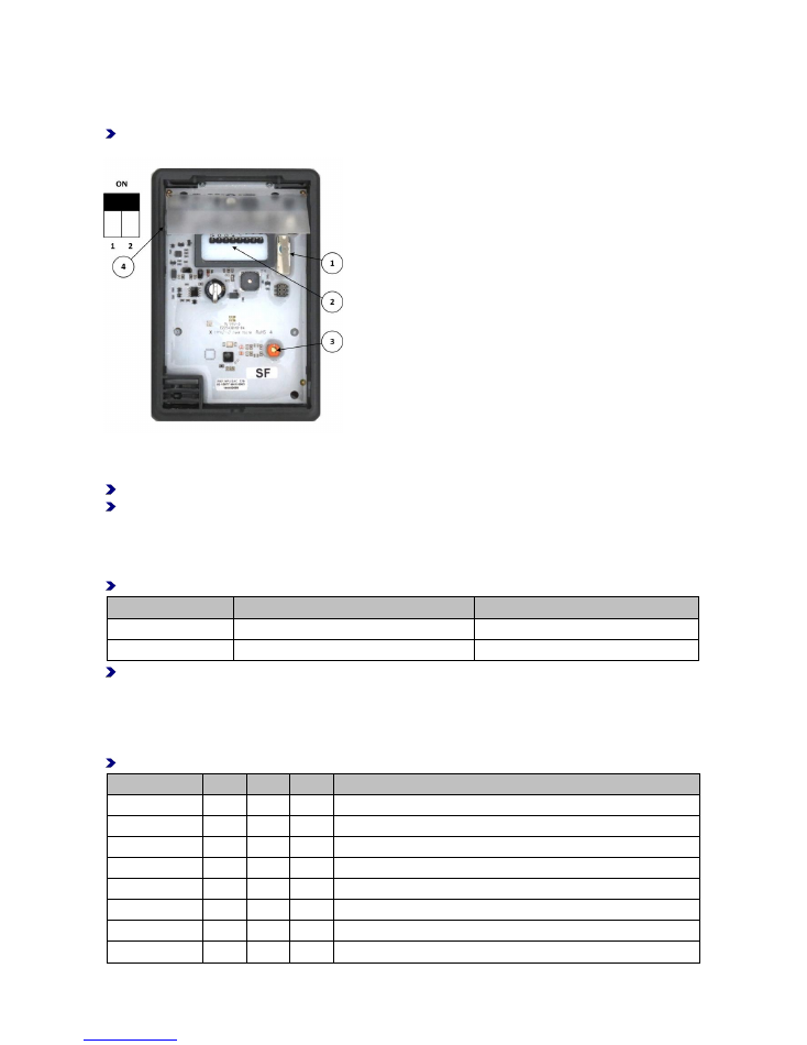
5 Synchronizing the Reader and Setting the LED Color
Structural conditions may make it necessary to fine-tune or readjust the reader. To do so, the adjustment set
with the order number 75-99-0004 is required.
In order to achieve the best result, perform fine tuning at the location of use while the back panel is
attached.
1
Anti-tamper switch
3
Screw for adjusting the reader
2
Terminal clamps
4
2-pin DIP switch for setting the LEDs
Switch on the power supply.
Turn the adjusting screw (3) until the field indicator reaches maximum.
Setting the LEDs
Use the DIP switch (4) to set the LEDs according to the color of the display. The switch setting is usually
preset (factory default).
Check the setting of the DIP switches according to the table specifications.
Design
Switch 1/design color white
Switch 2/design color blue
Glass, white
OFF
ON
Glass, black
ON
ON
Further settings are reserved for other designs.
6 Device Settings
6.1 Setting the hardware address
Use the address switch to set the hardware address of the device.
Switch
4
3
2
1
Address 1
OFF
OFF
OFF
OFF (not required if connected to a master terminal)
Address 2
OFF
OFF
OFF
ON
Address 3
OFF
OFF
ON
OFF
Address 4
OFF
OFF
ON
ON
Address 5
OFF
ON
OFF
OFF
Address 6
OFF
ON
OFF
ON
Address 7
OFF
ON
ON
OFF
Address 8
OFF
ON
ON
ON
Interflex Datensysteme GmbH
11/13
6.2 Setting the address without an I/O controller board
If an I/O controller board without an address switch is used, you can set the address of the IF-80x Outdoor
terminal via the RS-485 data cable.
Once the terminal is connected to the controller, it responds with host address 8.
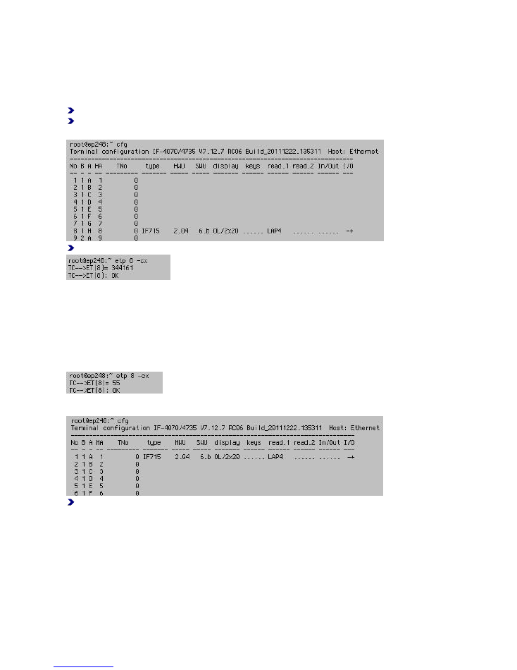
Set the address of the terminal with a Telnet connection via the controller as follows:
Set up the connection to the controller with Telnet.
Use the command
cfg
to retrieve the terminal number.
Example:
cfg
-> address 8 has been set.
Enter this command:
etp <address> -cx
The controller responds with TC-->ET(8)=
Then, the command 34xxyy is sent directly to the terminal.
Example: Address 1:
xx = New address A (uppercase) corresponds to 41(Hex)
xx = New address a (lowercase) corresponds to 61(Hex)
The command for setting address 1 is: 344161
Correspondingly for address 2: 344262 (see table).
Via a warm boot (command 55), the terminal then recognizes its new address:
After approximately 10 seconds, the terminal is ready for operation and can be checked via the cfg
command:
Make sure that an address is not used twice. The address must be within the address range of the
controller (IF-4070).
Interflex Datensysteme GmbH
12/13
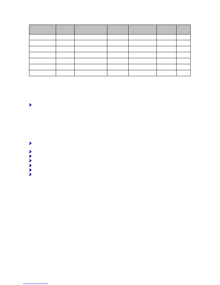
This table applies to a controller with 8 possible terminals on bus 1:
Old Address
Old HA
Controller
Command
Command
New Address
New HA
Bus
H
8
etp 8 -cx
344161
A
1
1
H
8
etp 8 -cx
344262
B
2
1
H
8
etp 8 -cx
344363
C
3
1
H
8
etp 8 -cx
344565
E
5
1
...
8
etp 8 -cx
...
..
...
...
A
1
etp 1 -cx
344868
H
8
1
A
9
etp 9 -cx
344262
B
2
2
6.3 Bridges on the I/O controller board
Check the setting of the bridges and adjust them, if necessary:
Br. 1:
When one I/O controller board is used, bridge 1 is always plugged in.
If a second I/O controller board is used, remove bridge 1 on the second I/O controller board.
Br. 2
: Bridge 2 is used to set the switching contacts of the NO/NC relay.
Br. 3
: Instead of bridge 3, an anti-tamper switch can be connected.
See also
Wiring Overview ........................................................................................................................ 8
7 Initial Operation
Once you have connected the IF-80x Outdoor terminal and set the address, lock it using the mortise
lock.
Additionally fasten the device with the included M2 x 6 mm countersunk head screw.
Switch on the power supply.
Configure the terminal in your host software, e.g. the IF-6040 system.
Make sure that your software recognizes and controls (online operation) the terminal.
Perform a booking at the terminal with a suitable credential.
Make sure that the booking reaches your host system where it is further processed.
For further diagnosis purposes, special programs and tools are available to system engineers and
consultants.
Interflex Datensysteme GmbH
13/13
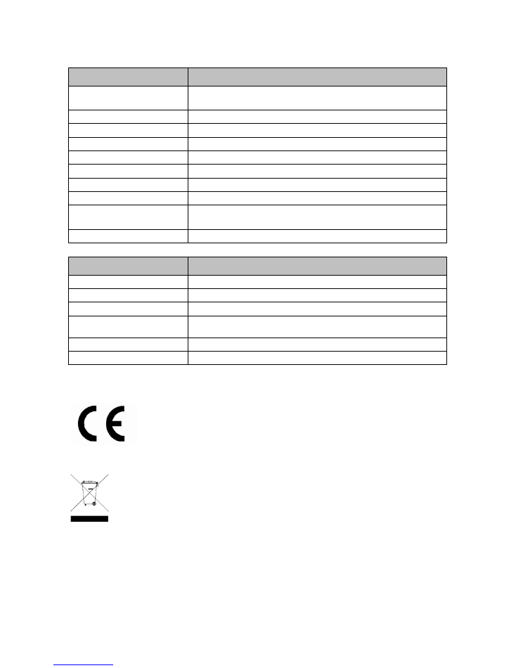
8 Technical Specifications
IF-80x Outdoor
Power Supply
- 12 to 27 V AC
- 11 to 38 V DC
Power consumption
Max. 4 VA
Protection
via PTC resistor
Interfaces
RS-485, 9600/19200 baud (automatic recognition)
Reader for
RFID credentials (Mifare or LEGIC as per order)
Inputs
2 for floating status contacts (4 with 2 I/O controller boards)
Output relays
1, max. 30 V, 2 A (2 with 2 I/O controller boards)
User information
Buzzer; green/red LEDs and, depending on the display color, blue or white
Data entry
- IF-800 Outdoor: no input facility
- IF-801 Outdoor: Keyboard with numeric keypad
Protection against sabotage
Anti-tamper switch. Switches when front panel is removed.
General Data
Ambient temperature
-25°C to +55°C
Humidity
Max. 95%, non-condensing
Protection category
III
Degree of protection
IP54, provided that the cables are installed according to instructions. The lower
cable inlet must be masked using the included adhesive strip.
Dimensions (L x W x D in mm):
130.5 x 87 x 24
Weight
0.5 kg
9 EU Declaration of Conformity
Interflex hereby declares that the products comply with the directives 2014/53/EU and
2011/65/EU.
The complete EU Declaration of Conformity is available at the following Internet
address:
www.interflex.de/en/header/downloads/ce_declaration_of_conformity.html
10 Disposal
Once its service life comes to an end, the device must be disposed of properly as
electronic waste. The owner can dispose of the device himself or return it to the
supplier.
Copyright © 2017
Version Date: July 28, 2017
Interflex Datensysteme GmbH
Zettachring 16, D-70567 Stuttgart, Germany
Tel.: +49 (0711) 1322 0
Internet E-Mail: interflex.info@allegion.com
Websites:
www.interflex.de www.allegion.com