Full Text Searchable PDF User Manual
OUTDOOR
TM
Keep the instructions
for future reference.
This IM applies to both SRPH67 & SRPH69.
GB
2
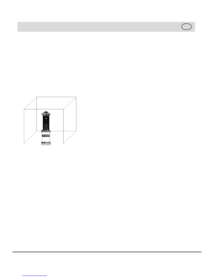
WARNING
1. For use outdoors or in amply ventilated
areas.
2. An amply ventilated area must have a mini-
mum of 25% of the surface area open.
3. The surface area is the sum of the walls
surface.
4. This appliance is not fitted with “Atmo-
sphere sensing device”.
WARNING:
Read the instructions before
installation and use.
Warning:
This appliance must be installed
and the gas cylinder stored in accordance
with the regulations in force.
Warning:
Use only the type of gas and the
type of cylinder specified by the manufac-
turer.
Warning:
Do not obstruct the ventilation
holes of the cylinder housing.
Warning:
In case of violent wind particular
attention must be taken against tilting of the
appliance.
Warning:
Do not move the appliance when in
operation.
Warning:
Shut off the valve at the gas cylin-
der or the regulator before moving the appli-
ance.
Warning:
The
Warning:
The heater can’t be used when the
tubing or the flexible hose
must be changed within the prescribed inter-
vals.
GB
heat exchange tube is retracted into cylinder
compartment.
WARNING:
The use of this appliance in
enclosed areas can be dangerous and is
PROHIBITED.
Warning:
Do NOT keep the heater fully
extended and the heat exchange tube must be
lowered down to position during transportation!
Country
Category Nominal heat
input(Hs)
Gas
consumption
Injector
diameter(Ø)
Gas & Pressure
AT CH
DE
SK
I
3B/P(50)
11kW
800 g/h(G30)
800 g/h(G30)
1.39mm
G30 Butane and
G31 Propane at
50mbar
BE CY
DK
EE
FI
FR
HU IT
LT
NL
NO SE
SI
SK
RO
HR TR
BG
IS
LU
MT
I
3B/P(30)
11kW
800 g/h(G30)
1.67mm
G30 Butane and
G31 Propane at
30mbar
BE CH CY
CZ ES FR
GB GR
I E
IT
L T
LU
LV PT SK
SI
PL
I
3+(28-30/37)
11kW
I
3B/P(37)
11kW
800 g/h (G30) 1.67mm
1.67mm
G30 Butane at
28-30mbar
and
G31 Propane at
37mbar
3
Technical data
GB
Manufacturer:
SHINERICH INDUSTRIAL LIMITED
Address: 8/F, Noble Center, 1006 Fuzhong
3rd Road, Futian District, Shenzhen,GD
518026, CHINA
Phone: +86 - 755 - 8826 7676
For questions, replacement parts, service
help, or other assistance, please call
Distributor name
Address:
Email:
G30 Butane and
G31 Propane at
37mbar
4
GB
Find a large, clean area to assemble your
appliance. Please refer to the parts list and
assembly diagram as necessary.
Please use protective gloves when assem-
bling this product.
To avoid losing any small component or
hardware, assemble your product on a hard
level surface that does not have cracks or
openings.
To avoid damage to soft floor or carpet, do
not assemble or move the appliance on soft
floor or carpet.
Follow all steps in order to properly
assemble your product.
Make sure all the plastic protection rip off
before assembling.
Do not force parts together as this can result
in personal injury or damage to the product.
When applicable, tighten all hardware con-
nections by hand first, once the step is com-
pleted, go back and full tighten all hardware.
Caution: Whilst every effort has made in
manufacture of your appliance to remove
any sharp edge, you should handle all com-
ponents with care to avoid accidental injury.
Time to assemble
Number of people required to assemble
One people
Assembly instructions
10 minutes

5
Further information
GB
Disconnect LP Gas cylinder
Before disconnecting make sure the LP gas
tank valve in “CLOSED”. Disconnect gas line
from LP gas cylinder by turning knob
counterclockwise until it is loose.
For storage and cylinder exchange, discon-
nect hose at the cylinder only, DO NOT
disconnect hose from appliance.
To change the gas cylinder in an amply ven-
tilated area, away from any ignition source
(candle, cigarettes, other flame producing
appliances…).
LPG cylinder not provided. The appliance is
designed to operate with a cylinder of size Ø
31.8 x 58 cm.
This appliance requires a 15 kg butane LPG
cylinder or a 13 kg propane LPG cylinder.
Gas regulator should be the correct one and
be set according to specific gas category
(see Technical data on page 3).
Gas regulator should be approved according
to EN 12864 with proper capacity (g/h), pres-
sure, working temperature and inlet + outlet
connection for the country of destination.
The regulator illustrated on the manual is for
United Kingdom, the regulator in your country
maybe different with the one on the illustration.
Flexible gas rubber pipe should be approved
according to EN 1763-1 with proper inner Ø
to match pipe holders of gas circuit and gas
regulator, pressure and working tempera-
ture.
The length of the hose is 0.41 m and it
should not exceed 0.7 m. The hose shall be
readily visible across its entire length for
inspection after installation.
Danger:
You must have the proper regulator and
cylinder in order for the appliance to operate
safely and efficiently. Use of an incorrect or
faulty regulator is dangerous and will invali-
date any warranty.
Connect LP Gas cylinder
Before connecting, be sure that there is no
debris caught in the head of the LP tank,
head of the regulator valve or in the head
of the burner and burner ports.
Connect gas line to tank by turning knob
clockwise until it stops, make sure that the
tube is not subject to twisting.
After connecting to gas cylinder, a leak test-
ing is necessary.
Important Notes:
6
GB
Leak testing (to be performed in a well-
ventilated area)
Your Outdoor Patio Heater has been
checked for leaks at all the factory made
connections. To check the connection of the
gas hose/regulator/LPG cylinder.
1) Make leak test solution by mixing 1 part
washing up liquid and 3 parts water.
2) Spoon several drops (or use squirt bottle)
of the solution onto the gas hose/regulator
and regulator/LPG cylinder connection.
3) Inspect the connections and look for
bubbles.
4) If no bubbles appear, the connection is
safe.
If bubbles appear, there is leak, loosen and
re-tighten this connection. Repeat the test.
If bubbles form again, stop trying; contact
your local dealer for assistance.
Leak test annually, and whenever the gas
cylinder is removed or replaced.
Note:
In the event of gas leakage, the appli-
ance must not be used or if already alight,
the gas supply must be shut off and the
appliance investigated and rectified before it
is used again.
7
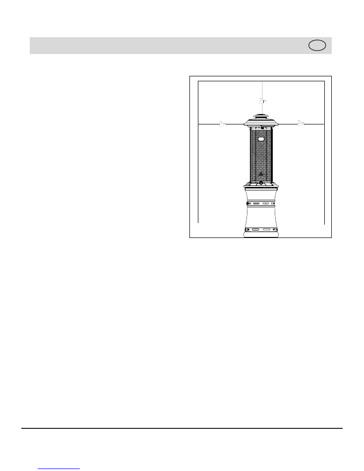
GB
Minimum clearance from combustible
surfaces
This heater is primarily used for the heating
of outdoor patios, decks, spas, pools and
open working areas.
Combustible materials are considered to be
wood, compressed parter, plant fibres, plas-
tic or other materials that are capable of
being ignited and burned.
Always make sure that adequate fresh air
ventilation is provided. Follow the spacing
tolerances shown in the following figure right
at all times.
This heater must be placed on level, firm
ground.
Never operate in an explosive atmosphere.
Keep away from areas where gasoline or
other flammable liquids or vapors are stored
or used.
8
GB
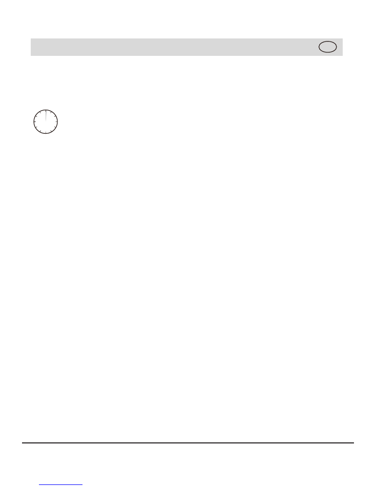
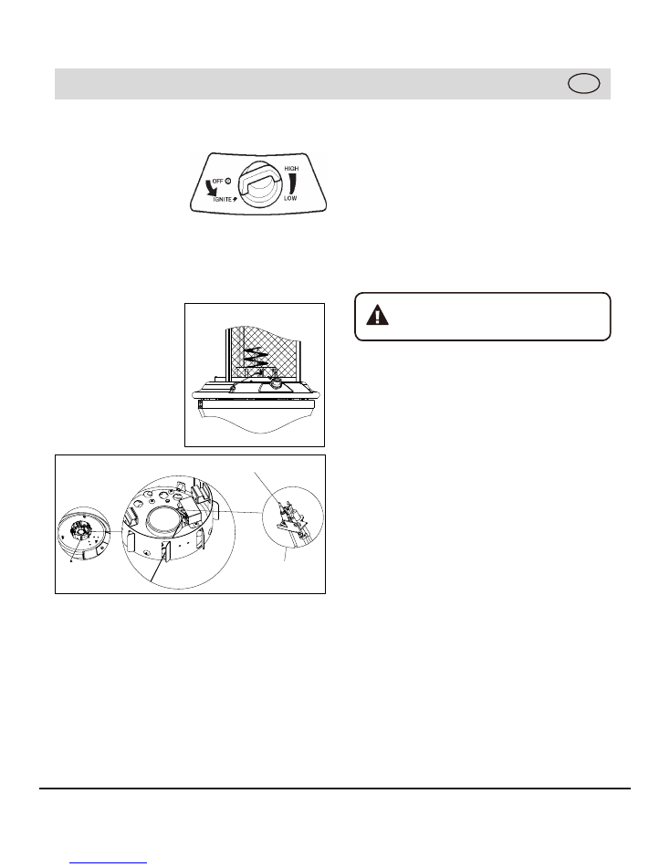
LIGHTING PROCEDURE
1. Turn the control knob OFF. Slowly open
the gas cylinder valve.
2. Push in and turn
control knob
anti-clockwise to
IGNITE.
3. Keep control knob depressed for up to 30
seconds until pilot is lit.
If pilot does not light, turn control knob to
OFF and wait 5
minutes between
ignition attempts for
gas to dissipate.
Note:
it is possible
to light the appliance
using a long match,
by lighting the burner
through the ignition
hole provided.
4. When the pilot is lit keep knob pressed
for up to 20 seconds to heat the thermo-
couple flame sensor, then release it (first
ignition generally takes more time, because
the gas circuit is full of air).
5. If the pilot does not stay lit, repeat steps
2 - 4.
6. Turn knob to LOW position.
7. Adjust the heat input by turning the knob
from the LOW position, to the HIGH posi-
tion, as required.
8. After lighting, turn knob from LOW to
HIGH, position and back, to check flame
stability.
9. In case of accidental break down of the
flame (due to wind or other reasons), a
Flame Safely Device (FSD) will automati-
cally shut-off gas supply within 90 seconds.
Flame Characteristic
The flame pattern at the emitter screen
should be visually checked whenever heater
is operated.
If black soot is accumulating on the emitter
grid or reflector, the heater should be
turned
off
immediately. The heater should not be
operated again until the unit is serviced and
or repaired.
These lighting instructions must be
followed. An unsafe condition can
occur if they are not followed correctly.
Thermocouple
Pilot Assembly
9
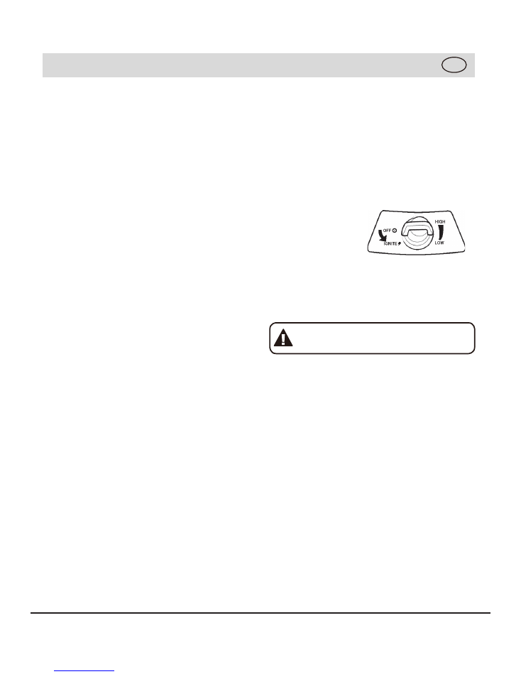
Shut down instructions:
1. Push in and turn control knob clockwise
to OFF position.
2. Turn LPG cylinder gas valve clockwise to
OFF position when heater is not in use.
Note:
After use, some discolouration of the
emitter screen is nomal.
The event of gas leakage:
1. Turn the
control knob
to OFF position.
2. Turn LPG
cylinder valve
to OFF position.
3. Wait 5 minutes to allow gas to dissipate.
4. If odor continues, immediately call
gas supplier.
Warning:
Heater will be hot after use.
Handle with extreme care.
GB
OPERATING PROCEDURE
Note: The burner may be noisy when initially
turned on, To eliminate excessive noise from
the burner, turn the control knob to the LOW
position. Then, turn the knob to the level of
heat desired.
When heater is ON:
Emitter grid will become bright red due to
intense heat. The colour is more visible at
night. Burner will display tongues of blue
flame. These flames should not produce
thick black smoke, indicating an obstruction
of airflow through the burners.
Operation pressure checked:
If the flame is very small, this is because the
supply pressure is not enough. Please refill
gas cylinder.
Re-light:
1. Turn the control knob to OFF position.
2. Wait five (5) minutes before attempting to
relight pilot.
3. Repeat steps beginning with step 2 of the
lighting instruction above.
10
Cleaning and maintenance
To enjoy years of outstanding performance
from your heater make sure you perform the
following maintenance activities on a regular
basis:
● Keep exterior surfaces clean.
●
Use warm soapy water for
cleaning.
Never
use flammable or corrosive cleaning agents.
●
While washing your unit, be sure to keep
the area around the burner and pilot assem-
bly dry at all
times.
If the gas control is
exposed
to water in any way, do NOT try to
use it. It must be replaced.
●
Air flow must not be
obstructed.
Keep
con-
trols, burner, and circulating air passage-
ways
clean.
Signs of possible blockage
include:
Gas odor with
extreme
yellow tipping of
flame.
Appliance does NOT reach the desired tem-
perature.
Appliance glow is excessively uneven.
Appliance makes popping noises.
●
Spiders and insects nest in burner or
orifices.
This dangerous condition can
damage heater and render it unsafe for
use.
Clean burner holes by using a heavy-duty
pipe
cleaner.
Compressed air may help clear
away small particles.
●
Carbon deposits may create a fire
hazard.
Clean heat reflector with warm
soapy
water
if any carbon deposits develop.
GB
Check the tubing or the
flexible
hose (at
least once per month and each time the
cylinder is
changed).
If it shows signs of
cracking, splitting or other deterioration, it
must be
exchanged
for a new hose of the
same length and of the equivalent quality.
STORAGE
Between uses:
● Turn the control knob to OFF position.
● Turn LPG cylinder to OFF position.
●
Store appliance upright in an area
sheltered from direct contact with inclement
weather (such as rain, sleet, hail, snow, dust
and debris).
●
If desired, cover appliance to protect
exterior surfaces and to help prevent debris
in air passages.
During periods of extended inactivity or
when NOTE transporting;
●
Turn the control knob to
OFF
position (full
disk). before covering.
●
Disconnect
LPG
Cylinder and move to a
secure, well-ventilated location
outdoors.
DO NOT store in a location that will
exceed
50 °C.
●
The
LPG
cylinder must be kept out of
reach of children, and not in a building,
garage or any other enclosed area.
●
Store
●
●
●
Remove safety screws. Remove knob from
Keep gas chamber door partially open. Turn
control panel and store in door.
appliance upright in an area shel-
tered from direct contact with inclement
weather (such as rain, sleet, hail, snow, dust
and debris).
●Always
remove the battery from the patio
flare if not being used for long periods of time
as battery leakage can cause corrosion in
the battery ignition housing.
●
If desired, cover appliance to protect
exte
-
rior surfaces and to help prevent debris in air
passages.
NOTE
Wait until appliance is cool before
covering.
Slowly descend heat exchange tube.
heat exchange tube clockwise.
11
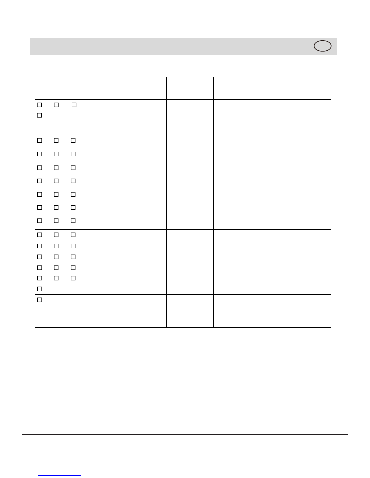
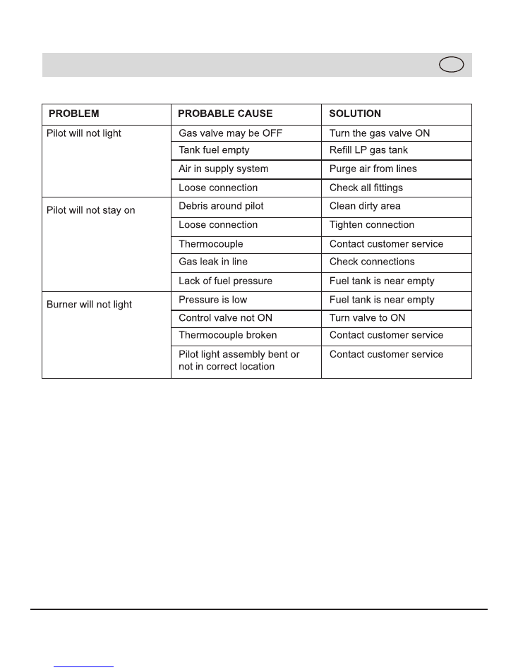
TROUBLESHOOTING
GB
12
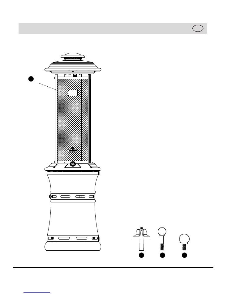
EXPLODED VIEW
GB
2
3
4
1
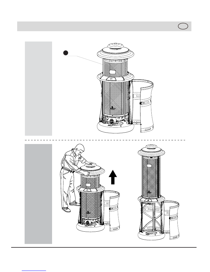
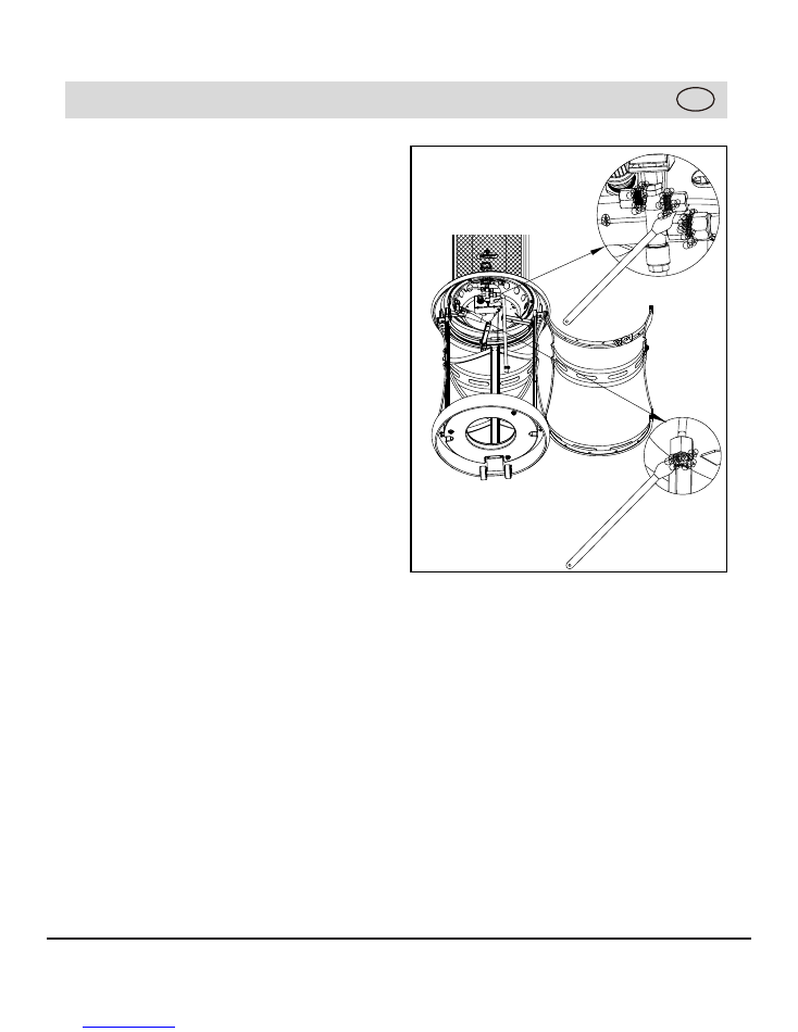
ASSEMBLY INSTRUCTIONS
13
1
2
GB
1
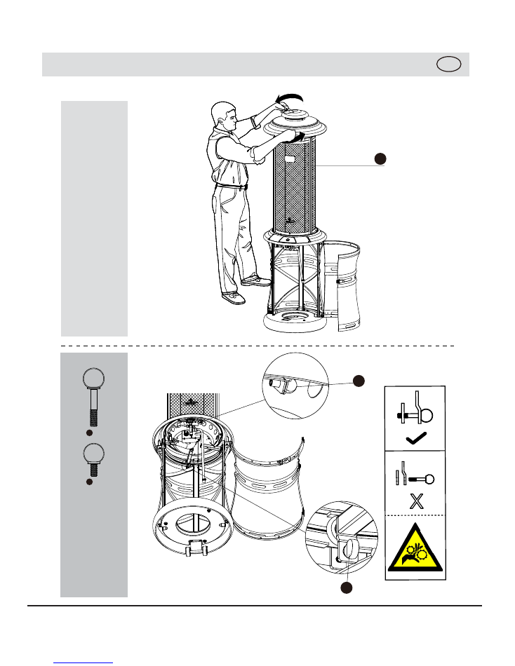
14
3
4
ASSEMBLY INSTRUCTIONS
GB
1
4
3
3
4
X1
X1
X
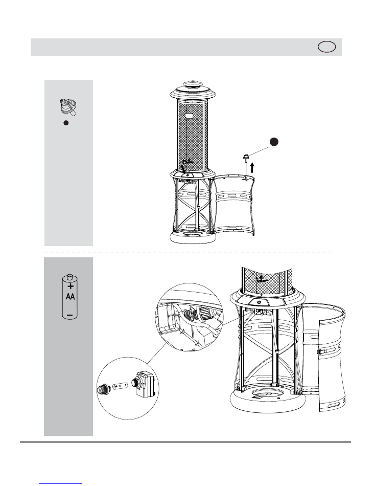
15
5
6
x1
(not included)
ASSEMBLY INSTRUCTIONS
GB
2
2
16
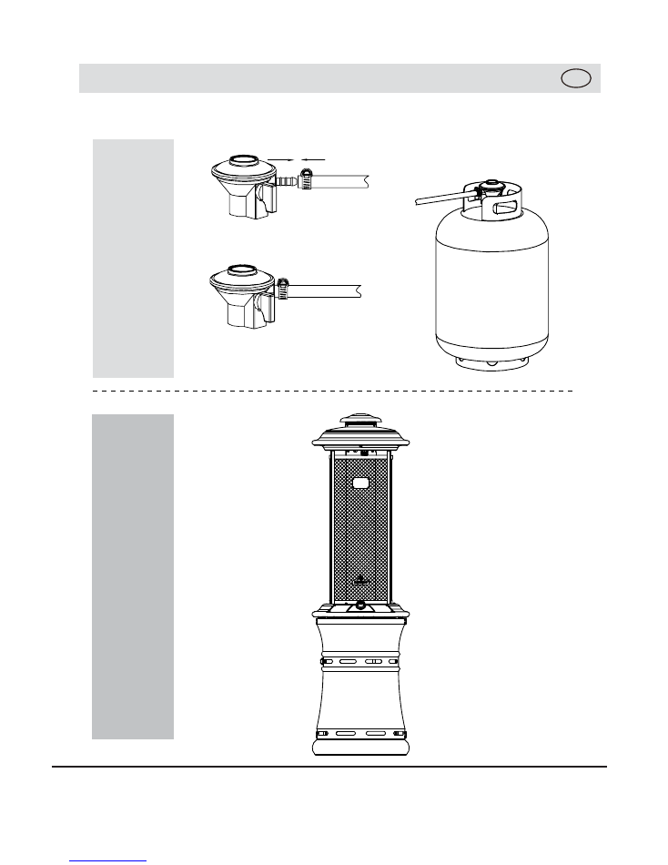
7
8
ASSEMBLY INSTRUCTIONS
GB