Full Text Searchable PDF User Manual
Doc. SIE20167
Rev. 2
Date 27/03/2013
BTS200 MKII
BATTERY TEST SET
Shop for Power Metering products online at:
1.877.766.5412
www.
PowerMeterStore
.ca

Doc. SIE20167
Rev. 2
Page
3 of 11
INDEX
1 GENERAL DESCRIPTION _____________________________________________________________ 4
2 APPLICABLE STANDARDS ___________________________________________________________ 6
2.1 Electromagnetic Compatibility _______________________________________________________________ 6
2.2 Low voltage directive _______________________________________________________________________ 6
3 PERFORMANCE SUMMARY ___________________________________________________________ 7
3.1 Introduction ______________________________________________________________________________ 7
3.2 Specification ______________________________________________________________________________ 8
Shop for Power Metering products online at:
1.877.766.5412
www.
PowerMeterStore
.ca
Doc. SIE20167
Rev. 2
Page
4 of 11
1 GENERAL DESCRIPTION
This technical specification is to describe the technical characteristics of the battery test set
BTS200 MKII, designed for the test of battery benches using the discharge method. This testing
device can discharge the battery in different modes, to measure the capacity of new and used
battery. With respect to the former BTS200, the MKII uses a technological improvement, that has
allowed to reduce weight and dimensions.
BTS200 MKII allows the connection to up to nine auxiliary modules type ELU200 MKII (or
ELU200, or other BTS200 MKII, or other BTS200), that enhance the discharging capability.
With the optional current clamp, or with the external shunt, it is also possible to use the real
burden as the additional burden, and to control the total discharging current in the selected mode.
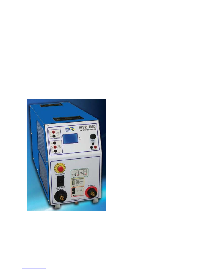
The device is microprocessor based. This allows the control of all the discharging parameters in
real time. It also allows communication with a PC for the control and the data representation of the
discharging parameters. The following is the test set picture.
With respect to the former version, MKII features the following improvements.
The weight has been decreased of 9 kg, from 48 kg to 39 kg.
Dimensions have been reduced, from 283 x 803 x 420 mm (WDH) to 283 x 700 x 420
mm.
Two wheels have been added, to ease the transport.
The number of discharging steps that can be programmed have been increased from 10 to
20: this eases drawing any discharge profile.
Shop for Power Metering products online at:
1.877.766.5412
www.
PowerMeterStore
.ca

Doc. SIE20167
Rev. 2
Page
5 of 11
In addition to the external clamp, the external burden current can now be measured also
with a shunt.
If a test is interrupted, for instance because of a faulty contact or cell, after the repair it is
possible to continue the test: this was not possible with the former device.
The test set firmware can be upgraded with a supplied software.
Shop for Power Metering products online at:
1.877.766.5412
www.
PowerMeterStore
.ca

Doc. SIE20167
Rev. 2
Page
6 of 11
2 APPLICABLE STANDARDS
The test set conforms to the EEC directives regarding Electromagnetic Compatibility and Low
Voltage instruments.
2.1 Electromagnetic Compatibility
Directive no. 2004/108/EC. Applicable Standard : EN61326-1 + A1 + A2.
EMISSION
- EN61000-3-2: harmonic content induced into the power supply: class A.
- EN 61000-3-3: Limitation of voltage fluctuations and flicker. Acceptable limits: basic.
- CISPR16 (EN 55011 class A): Limits and measurement methods of radio-electric disturbances
for industrial, medical and scientific instruments at radio-electric frequencies.
Acceptable limits for conducted emission:
. 0.15-0.5 MHz:
79 dB pk; 66 dB avg.
. 0.5-5 MHz:
73 dB pk; 60 dB avg.
. 5-30 MHz:
73 dB pk; 60 dB avg.
Acceptable limits for radiated emission:
. 30-230 MHz:
40 dB (30 m)
. 230-1000 MHz:
47 dB (30 m)
IMMUNITY
- EN 61000-4-2: Immunity tests for ESD. Test values: 8 kV in air; 4 kV in contact.
- EN 61000-4-3; Immunity tests for radio frequency interference. Test values (f= 900
5 MHz):
field 10 V/m, modulated AM 80%; 1 kHz
- EN 61000-4-4; Immunity tests for high speed transients (burst). Test values: 2 kV peak; 5/50 ns.
- EN 61000-4-5; Immunity tests for surge. Test values: 1 kV peak differential mode; 2 kV peak
common mode; 1.2/50 us.
- EN 61000-4-6: immunity to low-voltage sinusoidal waveform. Test values: 0.15-80 MHz, 3
Vrms, 80% AM 1 kHz.
- EN 61000-4-8: Immunity tests for low frequency magnetic fields. Test values: 30 Arms/m.
- EN 61000-4-11: Immunity test for power supply drops. Test value: 1 cycle; 100% drop.
2.2 Low voltage directive
- Directive n. 2006/95/EC.
Applicable standards, for a class I instrument, pollution degree 2, Installation category II: CEI EN
61010-1. In particular:
- Dielectric Rigidity: 1.4 kV, 1 minute.
- Isolation resistance: > 100 Mohm @ 500 V DC.
- Earth resistance : < 0.1 Ohm.
- Dispersion current: < 5 mA.
- Inputs/outputs protection: IP 20 - IEC 60529.
- Acoustic noise: < 75 dB, at full power.
- Operating temperature: 0 - 40°C; storage: -25°C to 70°C.
- Relative humidity : 5 - 95%, not condensing.
- Vibration: IEC 68-2-6 (20 m/s^2 at 10 – 150 Hz);
- Shock: IEC 68-2-27 (15 g; 11 ms; half-sine).
- Altitude: less than 2000 m.
Shop for Power Metering products online at:
1.877.766.5412
www.
PowerMeterStore
.ca

Doc. SIE20167
Rev. 2
Page
7 of 11
3 PERFORMANCE SUMMARY
3.1 Introduction
BTS200 MKII can discharge batteries with different nominal voltages, from 24 V to 240 V DC.
The discharging current can be up to 130 A for voltages of 24 to 120 V DC nominal, and up to 70
A for 220 to 240 V. It is possible to use in parallel up to 10 BTS200 MKII, thus arriving up to
1300 A for voltages of 24 to 120 V DC nominal, and up to 700 A for 220 to 240 V.
The use of BTS200 MKII is very simple:
Connect the cables to the battery to be discharged;
Power-on BTS200 MKII;
Choose the memory area where to save the test data;
Program the discharging current (or power);
Program the maximum discharge duration;
Program the minimum battery voltage;
Program the Ah to be discharged;
Press START.
During the discharge actual parameters are displayed on the graphic screen; all the measured
parameters are saved into the selected memory. It is also possible to connect BTS200 MKII to a
PC with TDMS: this allows to have on the PC display the discharging diagram.
Via PC, it is possible to download a current sequence with up to 20 steps, each step being
programmable in current and duration. This enables simulating a typical current profile
encountered during the day.
If, during the discharge, any of the programmed limits is trespassed, the test is immediately
stopped, and the alarm contact closed.
Once the test is finished it is possible to watch the discharging current and voltage on the display,
or to download the test result to the PC.
The selection of discharging parameters is performed using the encoder with confirmation switch,
and the graphic display. The operation is menu driven: turning the encoder knob it is possible to
select the desired operation; pressing it the selection is confirmed.
Optionally, it is possible to leave an external load connected to the battery under test. In this
situation, the externally discharged current will be measured by means of a DC current probe or
by a shunt: BTS200 MKII takes into account this current, and ensures that the total discharging
current is the programmed one.
The device is equipped with an emergency pushbutton, located on the front. When pressed, it
stops all the BTS200 MKII activities. The pushbutton is mechanically self-locking: the operator
has to rotate it in order to reset the normal operation.
The device can be powered by the battery under test itself, for batteries with a nominal voltage of
220 or 240 V; else, on the front is provided a power supply plug for a wide range AC supply.
Shop for Power Metering products online at:
1.877.766.5412
www.
PowerMeterStore
.ca

Doc. SIE20167
Rev. 2
Page
8 of 11
3.2 Specification
PARAMETER
VALUE
A) HARDWARE
Maximum number of paralleling test sets
10: 1 master, 9 slave
Absolute maximum battery voltage
270 V
Minimum battery voltage
18 V
Maximum power that can be discharged (one module)
16 kW
Maximum power that can be discharged (10 modules)
160 kW
Max discharging current from 24 V DC to 120 V DC (one
module)
130A
Max discharging current from 24V DC to 120 V DC (ten
modules)
1300A
Max discharging current from 220 V DC to 240 V DC (one
module)
70 A
Max discharging current from 220 V DC to 240 V DC (ten
modules)
700 A
Discharging modes: constant current; constant power;
current profile; manual adjustment
4
Discharging power resolution
100 W
Nominal battery ranges
24, 48, 110, 240 V DC
Battery range setting
Automatic, on 4 ranges, as test starts
24 V range limits
20 to 34 V DC
48 V range limits
34 to 60 V DC
72 V range limits
60 to 84 V DC
110/120 V range limits
84 to 140 V DC
240 V range limits
140 to 270 V DC
Maximum starting voltages on the 24 V range
20 to 35 V DC
Maximum starting voltages on the 48 V range
34 to 65 V DC
Maximum starting voltages on the 72 V range
58 to 97 V DC
Maximum starting voltages on the 110 V range
84 to 140 V DC
Maximum starting voltages on the 240 V range
169 to 270 V DC
Battery voltage measurement resolution
± 0.1 V DC
Battery voltage measurement accuracy
± 1% of the maximum range = 2.7 V
Battery current measurement resolution (direct and clip-on
CT)
1 A
Battery current measurement accuracy
± 1% of the maximum range = 1.3 A,
starting from 15 A
V and I measurements refresh period
15 s
Time measurement resolution
1 s
External clip-on CT conversion factor range (programmable) 1 to 500 mV. NOTE: the 1 mV range
is to be used for currents greater than
400 A.
External shunt voltage input
1 to 60 mV
External clip-on CT or shunt accuracy
± 2%
Audible end of test alarm buzzer
5 tones
Alarm output contact
1 SPDT
Display type
Graphic 128 x 64 points
Display backlight
YES
Shop for Power Metering products online at:
1.877.766.5412
www.
PowerMeterStore
.ca

Doc. SIE20167
Rev. 2
Page
9 of 11
PARAMETER
VALUE
Operator interface
Encoder with push-button
Test start
ON-OFF pushbutton
Test stop from a remote contact
YES
Alarms
10-segments LED bar with current
and alarms
Test system LED
Date and time
Yes, with back-up battery
PC communication
USB 2.0 interface
Paralleling interconnection
2 connectors: in-out
Paralleling interconnection cable type
CAN bus; RJ11 connector
Paralleling address selection
By rotary switch
Power supply modes:
Mode 1: from the battery being discharged;
Mode 2: from an AC voltage supply;
Mode 3: from an external DC voltage supply.
3 ways:
. 100 to 240 V DC
. 100 to 240 V AC, 50 to 60 Hz
. 100 to 270 V DC
Power supply mode selection
By switch
Power from the supply
. 10 W in stand-by;
. 150 W during the discharge.
Emergency push-button
Independent from the
microprocessors
Thermal protection
Independent from the
microprocessors
Dimensions
283 x 700 x 420 mm (WDH)
Weight
39 kg, without transport case.
Transport wheels
YES
Transport case dimension
330 x 900 x 600 mm (WDH)
Transport case weight
16 Kg
Provided with:
- USB connection cable, 2 m;
- RJ11 connection cable, 2 m;
- Battery discharge cable pair with
crocodiles;
- Power supply cable, 2 m;
- TDMS software
NOTES:
1. The above specified current and power ranges apply when the ambient temperature is 25 °C or
less. For higher temperatures, apply a de-rating factor of – 1 A/°C for the current; for the power, it
is the product of the voltage by the current scaling factor.
2. The absolute maximum ambient tempperature for full power operation is 40 °C.
3. The test set cannot operate with a direct sun exposition, or located nearby an heat source.
4. The test set generates very hot air, both above and on the rear: don’t touch it until the automatic
cooling down procedure is completed.
Shop for Power Metering products online at:
1.877.766.5412
www.
PowerMeterStore
.ca

Doc. SIE20167
Rev. 2
Page
10 of 11
PERFORMANCE
CHARACTERISTICS
B) RESIDENT FIRMWARE
Test settings
Recorded in a NVM
Number of memories
8
Maximum test duration that can be recorded
15 h, with 15 s resolution
Maximum test duration, not recorded in memory
infinite
Memory profile mode: maximum number of test steps
20
Memory profile mode: time and current resolution
1 minute – 1 A
Memory profile mode: maximum time and current steps
600 minutes – 1300 A
Test set control mode
Via encoder + push-button and
menu on the display
Measurements on the display
. Date;
. Time;
. Internal discharge current;
. External discharge current;
. Battery voltage;
. Ah discharged;
. Elapsed test time.
Test stop settings
. Minimum voltage;
. Maximum Ah;
. Maximum test time;
. System alarms;
. Test stop from remote contact.
Continue after an alarm
YES
Firmware upgrade
YES
System control
Digital, by two microprocessors
Test set protections
. Heat sink over-temperature;
. Fuse failure;
. Fans failure;
. Minimum battery voltage;
. Maximum battery voltage;
. Wrong battery voltage;
. Overload;
. Control circuit error;
. Power circuits failure;
. CAN-bus error;
. External current metering error;
. Manual emergency pressed;
. USB interface error;
. EEPROM memory error;
. Firmware error.
Reversed battery insertion protection
YES
Automatic cool down procedure at end of test
YES
Shop for Power Metering products online at:
1.877.766.5412
www.
PowerMeterStore
.ca

Doc. SIE20167
Rev. 2
Page
11 of 11
PERFORMANCE
CHARACTERISTICS
C) TDMS SOFTWARE
Create, save, upload test plans
Edit test profiles
Current discharge profile: diagram,
table
Upload test profiles
Download test results
Input reference data, save, recall
Examine test results
Result diagram, table of values
Zoom in-out
Cursors
Print test results
Printer editor capability
Customized report creation
Results and settings data base
Integrated in the TDMS Substation
data base
PERFORMANCE
CHARACTERISTICS
CODE
D) OPTIONS
Transport case, with wheels Dimensions:
330 x 900 x 600 mm; weight 16 kg.
PII18167
DC current clamp
Ranges: 40 A DC (10 mV/A) and 400 A DC (1 mV/A).
Accuracy: 1.5% up to 40 A; 2% up to 400 A.
Maximum conductor diameter: 30 mm.
PII12167
ELU200 MKII
Same as BTS200 MKII, without the local control
PII21167
The following table lists a number of different types of batteries, the discharge current and the
discharge power that can be programmed. The value chosen for the Ah capacity is just a reference
one: test current can be scaled to the actual capacity.
NOMINAL
BATTERY
VOLTAGE
V
NOMINAL
CAPACITY
Ah
CONSTANT
CURRENT
A
CONSTANT
POWER
kW
TEST
DURATION
h
DISCH.
CAPACITY
Ah
END
OF TEST
VOLTAGE
V
24
500
50
1
10
500
20
48
500
50
2
10
500
40
110
500
50
4.7
10
500
94
120
500
50
5.1
10
500
102
220
500
50
9.4
10
500
188
240
500
50
10.2
10
500
204
Shop for Power Metering products online at:
1.877.766.5412
www.
PowerMeterStore
.ca