Full Text Searchable PDF User Manual

Dear IRUS Customer,
You have made your decision for an IRUS machine. We would like to thank you for the trust you have
placed in us.
It is our desire that you will have just as much satisfaction with your IRUS machine as many thousands of
other IRUS customers have had in the past. This, of course, depends heavily upon a detailed knowledge of
the proper use of the machine. Before you begin using the machine, please have your sales representative
give you a detailed explanation and demonstration of the machine. Then, by all means, familiarize yourself
with this instruction manual. Although our devices are known by their simple operation and maintenance, it
is nevertheless important that you know as much as possible about the machine, because an incorrect
operation of the machine can lead to damages for which you must pay, even though they may take place
during the warranty period.
The safe handling and proper use of the machine will therefore be to your own benefit. So please keep in
mind that it is also up to you to really enjoy your new IRUS machine.
Warranty conditions:
We provide our equipment with a warranty for the period specified in the warranty card. During this time,
we will replace all parts which prove to have material or manufacturing defects. On the other hand, there is
no warranty for wearing parts such as starter ropes, V-belts, Bowden cables, etc., or for broken parts
caused by improper handling, lack of maintenance and care, or caused by failure to comply with the
operating instructions. If, during the warranty period, non specialised personnel attempt to repair the
machine themselves, this will void the warranty. Should any parts be installed that are not original IRUS
parts, this would also void the warranty.
Engines, which are not of IRUS manufacturing, are subject to the warranty conditions of their respective
manufacturers.
Important notice!
The enclosed warranty registration card is to be completed and signed by you and your dealer, and sent to
us immediately after the purchase of the equipment. No warranty will be recognized if no warranty
registration card has reached our office.
And now we wish you much satisfaction with your IRUS machine!
IRUS-Motorgeräte GmbH
Ind.geb. Häuslerwasen, D-72393 Burladingen-Salmendingen
Tel: +49(0)7126/928949-0 Fax: +49(0)7126/928949-99
Internet: http://www.irus.de/
Email: info@irus.de

Safety requirements and accident prevention regulations
Prior to the commissioning of the machine, the users must familiarize themselves with the operating and
safety regulations listed in the operating instructions. The safety regulations must be correctly observed
and all safety information passed on to others who operate this machine.
The UNITRAK implement carrier may only be operated in connection with original IRUS attachments,
according to manufacturer specifications. The operating instructions must be strictly observed, as IRUS will
assume no liability for damages resulting from neglect. The intended use of IRUS machines also includes the
observance of the operating and maintenance conditions prescribed by IRUS, as well as the exclusive use of
original IRUS spare parts. Unauthorized changes on the machine and the attachments will nullify any
liability of the manufacturer for damages resulting there from.
The warning and information signs attached to the device provide guidance for a
safe operation. Observing these signs is for your own safety and protection!
Always use gloves when handling the machine or mowing with the machine!
Always wear goggles and gloves when knife grinding!
The relevant accident prevention regulations, as well as the generally accepted technical, occupational
health and road traffic safety regulations must be strictly observed.
The operator bears the responsibility for the safety of people and animals that may find themselves within
the working area of the machine, and must take precautions that no third party is endangered or injured.
Children under 16 years are not allowed to operate the machine!
The operator must wear sturdy shoes and tight-fitting clothing.
Do not fill any fuel into the fuel tank whilst the engine is running or if it is still hot. Be careful to wipe up any
spilled fuel before starting the engine!
FIRE hazard!
Before starting the engine, the coupling lever must be pulled back and locked into place. The power take-
off lever as well as the control lever must be in the neutral (0) position.
When starting, nobody must be lingering in front of the machine.
Apply the throttle gently; a jerky movement could force the machine to tilt up on end.
Never leave the ignition key in the ignition switch (if electrically started).
The machine is never to be left unattended whilst the engine is running.
When working, be sure all safety guards are properly mounted.
After cleaning and after repair, all safety guards must be immediately reinstalled.
The machine operator must always maintain his distance to the machine as indicated by the steering bars.
Turn off the engine to do work of any kind on the machine. Cleaning is not recommended by hand, but
should be done using a suitable object between the spaces (a piece of wood or the like).
Should the machine be at risk of tipping over due to sloped terrain, an accompanying person may support
the machine by means of a holding rod or a guide rope. This accompanying person must be located above

the machine at a sufficient distance from the working tools.
Rain and/or moist soil increase the risk of slipping. If possible, therefore, only work on slopes or hillsides
with the weather permitting.
When starting the engine, the operator should not place himself in front of the machine or work tools.
Pacemaker carriers must not come in contact with current-carrying cables of the ignition while the engine
running.
No non-participating personnel must be allowed to come within the danger area!
Never start the engine in a closed room!
Internal combustion engines must not be operated in closed rooms; unless it can be assured that the
combustion gases are actively removed from the room. The exhausts contain hidden and odourless, but
highly toxic carbon monoxide. Attention:
Mortal Danger!
Attention!
For your own safety, all Bowden cables must be examined before every start-up. The area subject to wear
and tear on Bowden cables is where the cable exits the casing and around the area of the operating lever.
The function of the stop or deadman lever is also to be checked. In the case of defective Bowden or
deadman controls, the machine must not be put into operation, or all running operations must be
immediately stopped.
IRUS absolutely requires that you have your IRUS machine inspected for safety by an authorized repair shop
at least once a year.
General Description:
The basic
IRUS
UNITRAK
machine is a multi-functional tool carrier with infinitely variable hydrostatic drive.
Each wheel is driven by a separate hydraulic motor. The oil supply of these motors is provided by a variable
pump. With this propulsion machine, various attachments can be driven. All attachments are taken up by
the quick coupler and driven by the PTO shaft.
General Description:
Engine:
The
IRUS UNITRAK
is available with different engines (see separately enclosed operating manual for the
engine).
During the first 20 hours of operation (running-in time), the engine should not be taken to the limit of its
capacity. Cooling is provided by an air blower. For this reason, the grid for the cooling air and the cooling
fins of the cylinder should always be kept free from dirt and intake debris. It is important to make sure that
the engine idling speed is set correctly. The engine must continue to run properly at low rpm when the
throttle lever is fully at the stop in the idle position. The setting is to be made as described in the engine
manual.
Air Filter:
The air filter has the task of intercepting the dust contained in the intake air. Cleaning must be performed
regularly; even several times a day in case of heavy dust onset (see engine instructions). When noticing a
decline in engine power, always think first of cleaning the filter.
Coupler:
A triple-plate dry coupler serves as a multi-plate coupler.
Transmissions for PTO shaft:
High-quality speed reduction gears run in an oil bath.

Technical details:
Measurements:
Length: 1600 mm, without attachments
Width: 1150 mm (For terra tyres 23x10.50-12) Height: 1000 mm, depending
on the position of the steering bar
Transmission:
Hydrostatic
PTO shaft:
Engine PTO shaft: 970 rpm (at engine speed 3300 rpm)
Steering:
Active steering
Steering bar:
Infinitely variable in the absence of tools, adjustable to the left and right,
Mounted within anti-vibration elements.
Battery:
12 V, 18 Ah
Tyre Pressures:
0.8-1.8 bar for AS tyres 6-12
0.5-1.5 bar terra tyres 23x10.50-12
Oil filling quantities:
Engine: See Engine Operating Manual
Speed reduction gears: 0.6 litres of gear oil SAE 80W-90
Hydraulics: about 2.5 litres of biodegradable hydraulic oil PANOLIN HLP
SYNTH 68
Weight without wheels:
182 kg (basic machine 13 hp) / 190 kg (basic machine 18 hp)
Speeds:
Forwards 0-8 km/h, Backwards 0-6 km/h
infinitely variable
Slope suitability:
45 ° = 100%
Attention!!
When working on a slope, the oil level in the engine must be at the uppermost fill mark (max)!
The machine must be equipped with the appropriate auxiliary equipment such as additional
stabilizing wheels, steel cage wheels, etc.!
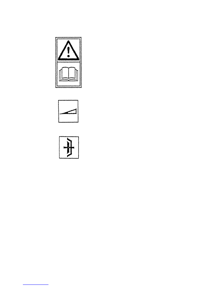
This symbol tells you that it is dangerous to operate
the machine without detailed knowledge of the
operating instructions.
Symbol for the throttle.
Noise level:
Measured at 1.8 m behind the handlebars (where the operator would be standing) with the measuring
instrument directed towards the machine.
At 85% of the rated engine speed.
Max continuous acoustic pressure:
Basic machine with twin blade mower unit 84.5 dB (A)
Vibrations:
Vibrations in the steering bar, measured according to ISO 5349:
At 85% of the rated engine speed with activated mower unit.
Basic machine with activated twin blade mower unit 4.9m/s²
.
Symbol for the coupler
The following dia
The following diagrams are located on the machine :
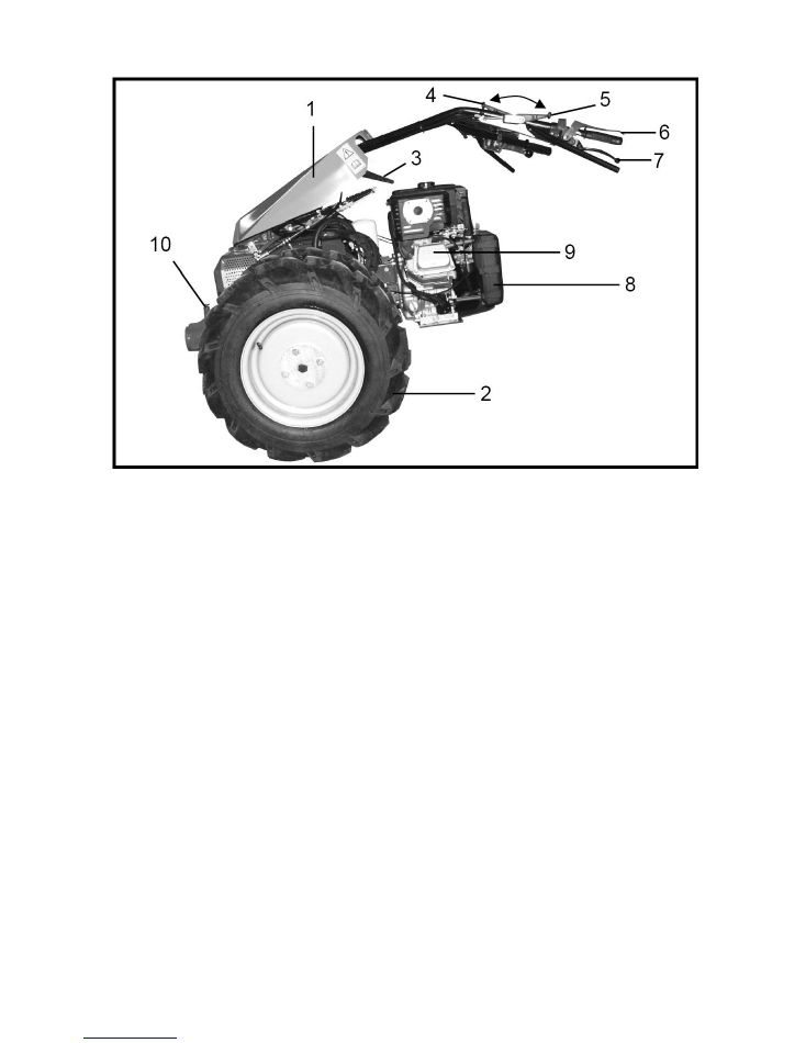
Figure 1
1 Steering rod cover
2 Wheels
3 Lever for variably adjustable handlebar height
4 Lever for handlebar side adjustment
5 ON/OFF lever to the PTO shaft
6 Deadman lever
7 Coupler lever
8 Air filter
9 Moto
Assembly of the basic machine:
The basic machine is delivered completely assembled.
Note:
Upon delivery, it is important that all screws, especially those on the wheels, are tightened again.
Once delivery has been made, IRUS requires the following work to be done as the initial inspection:
01. Motor check
02. Hydraulic oil level checks
03. Lubrication of the Bowden cables
04. Check of hydraulic connections for leaks
05. Functional testing of the steering
06. Functional testing of the deadman lever
07. Test run
08. Check of idle speed and maximum speed of the engine, corrections if necessary
09. Instructions to end user
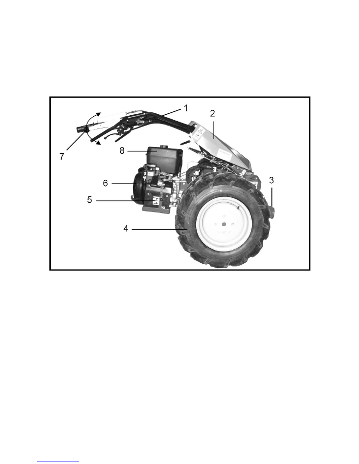
Figure 2
1 Steering bar
2 Steering rod cover
3 Attachment quick coupler
4 Wheels
5 Battery (only with electric start)
6 Grass guard
7 Throttle
8 Fuel tank
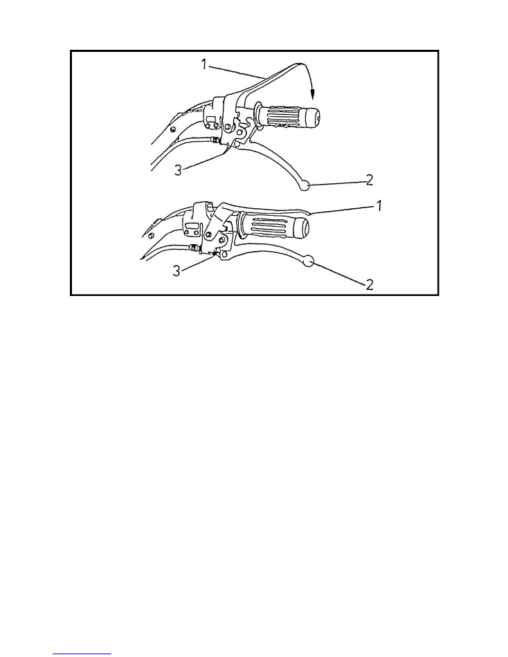
Figure 3
1 Engine stop lever
2 Coupler lever
3 Catch spring
Adjusting the steering bar to the correct working height:
Pull lever (Fig. 1/3) upward and release the steering bar. Move the steering bar to the desired height. Press
lever (Fig. 1/3) downward and clamp tight.
Lateral adjustment of the steering bar:
Pull lever (Fig. 1 / 4) and move the steering bar to the desired side. Release lever (Fig. 1 / 4) and push the
steering bar back and forth until the locking bolt locks into place.
Starting the engine:
See separate instructions included with the engine.

WARNING: RISK OF ACCIDENTS!!!
Before the engine can be started, it needs to be checked if both the control lever (Fig. 2/7) as well as the
PTO control lever (Fig. 1/5) are positioned at * 0 *. It must also be made sure that nobody is lingering in
front of the machine. Likewise, the person himself, who starts the engine, must also not be in front of the
machine.
01. Top-up the fuel tank and open the fuel tap.
02. Check the motor oil and top up, if necessary.
03. Press down the red engine stop lever (Fig. 3/1).
04. Pull up the coupler lever (Fig. 3/2).
05. Lock the coupler lever (Fig. 3) with the catch spring (Fig. 3/3).
06. Press the accelerator all the way down (full speed).
07. Apply the choke lever.
08. Turn the ignition key clockwise.
For further action concerning the motor, see separate engine operating manual!
Note:
After the engine is running, pull the coupler lever (Fig. 3/2) again a little bit to release the catch spring and
make the deadman lever operational.
Stopping the engine:
Turn the ignition key to the left and close the fuel tap.
Attention!
Only turn off the engine using the ignition switch and not the engine stop lever - otherwise it may drain
the battery!
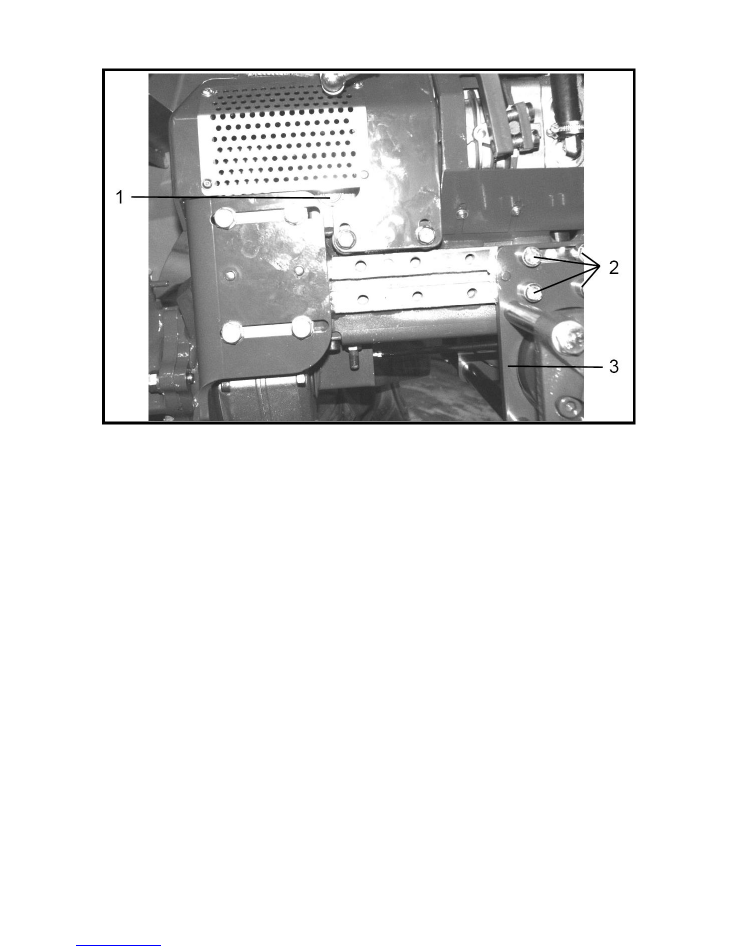
Figure 4
1 Oil gauge glass for the hydraulic oil level
2 Screws for fastening the axle
3 Axle
Installation of PTO attachments:
All PTO attachments are taken up by the quick coupler.
This is done as follows:
01. Pull out latch lock (Fig. 1/4) upwards and rotate 90°.
02. Mount devices (slide them into the quick coupler [Figure 2/3]).
03. Rotate latch lock again to 90 degrees and let it lock into place again. Make very sure that it has locked
into place!!!
Driving:
The
IRUS UNITRAK
is equipped with a variable drive system. By pushing the control lever (Fig. 2/7)
upwards, the machine is set in forward motion. The further the lever is moved, the faster the machine runs.
By moving the lever back, the machine slows down again. In the idling position, a catch can be felt on the
lever. The intensity of the latching can be adjusted (see maintenance work).
By pressing the control lever (Fig. 2/7) downward, the machine moves backwards in motion. The reverse
speed is also variable.
PTO:
The PTO is switched on by moving the lever (Fig. 1/5) forward. By moving the lever backward the PTO is
switched off.
Switching on:
01. Pull coupler lever (Fig. 1/7).
02. Move lever (Fig. 1/5) forward.
03. Let go the coupler lever (Fig. 1/7) slowly.
Switching off:
01. Pull coupler lever (Fig. 1/7).
02. Move lever (Fig. 1/5) backward.
03. Let go the coupler lever (Fig. 1/7) slowly.
Working:
01. Pull clutch lever (Figure 1/7).
02. Start the engine.
03. Engage the PTO.
04. Release clutch lever slowly.
05. Set the desired engine speed by operating the throttle accordingly.
06. Push the control lever slowly upward.
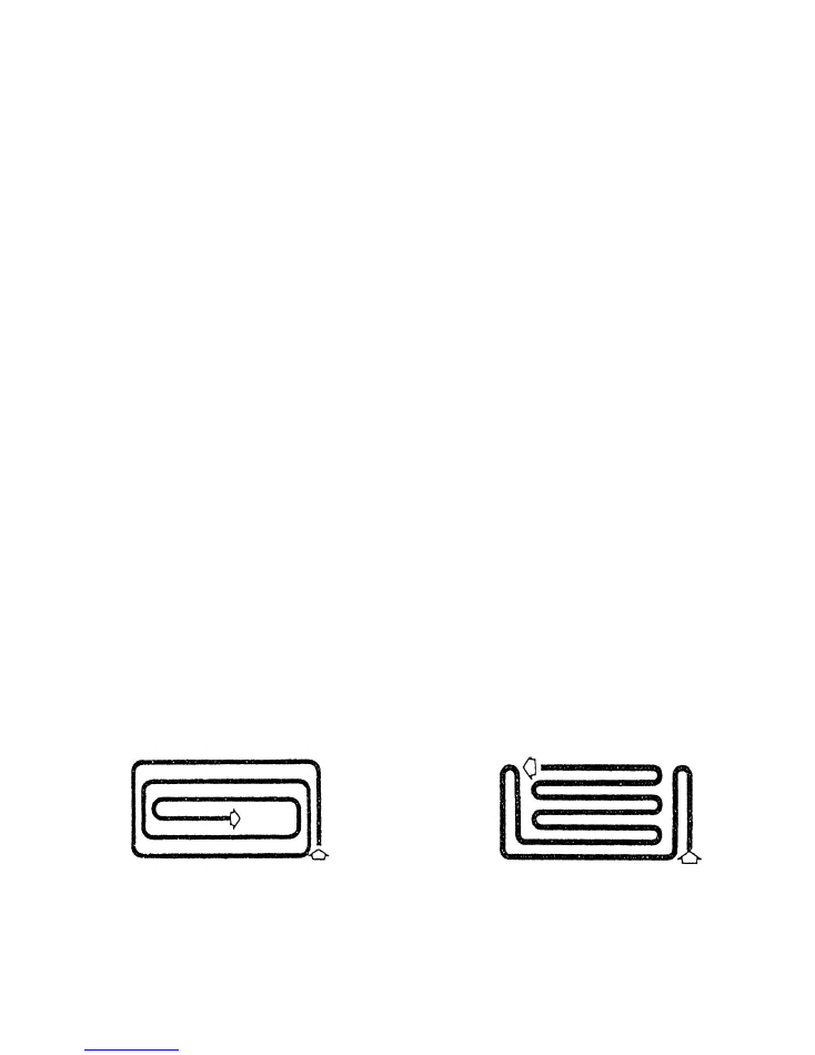
Pattern to be used when Pattern to be used when
working on flat even working on slopes.
ground.

Transportation of the machine:
Attention:
DANGER!
Before transporting the machine, turn off the engine and wait for the cutting tools to come to a complete
halt. The machine must be fastened according to the regulations in four directions. When driving the
machine outside of the working area, the attachment must likewise be switched off and the cutting tools
come to a complete halt.
Steering:
The
IRUS UNITRAK
is so designed that it always has the tendency to go straight ahead. Do not try to control
the machine forcibly at the steering bar. This is not necessary because the machine has an active steering
system.
The active steering system:
If you want to turn right, you only need to press the steering bar to the left and the machine moves to the
right. By
pressing the steering bar to the right, the machine moves to the left. Depending on how hard
you
press, the machine turns sharply, even with a jerky motion, or it moves gently into the curve. As soon as
you leave off from pushing to the sides, the machine drives straight ahead again.
WARNING!
Always work slopes going uphill only! RISK OF ACCIDENTS!
Moving the centre of gravity:
To be able to drive the machine comfortably while using various heavy attachments, the
IRUS UNITRAK
has
an adjusting axle.
If the axle is moved forward, the weight is shifted backwards, i.e. the pressure upon the mounting device is
less. The attachment can be lifted with less force upon the steering bar. If the axle is moved all the way
back, it is just the opposite. For every attachment, you need to choose the most convenient position.
Adjustment of the axle:
01. Loosen the four Allen screws on the right and left (Figure 4/2).
02. Operate the control lever (Fig. 2/5) in the direction in which you want to adjust the axis.
03. Torque up the four Allen screws again, right and left.
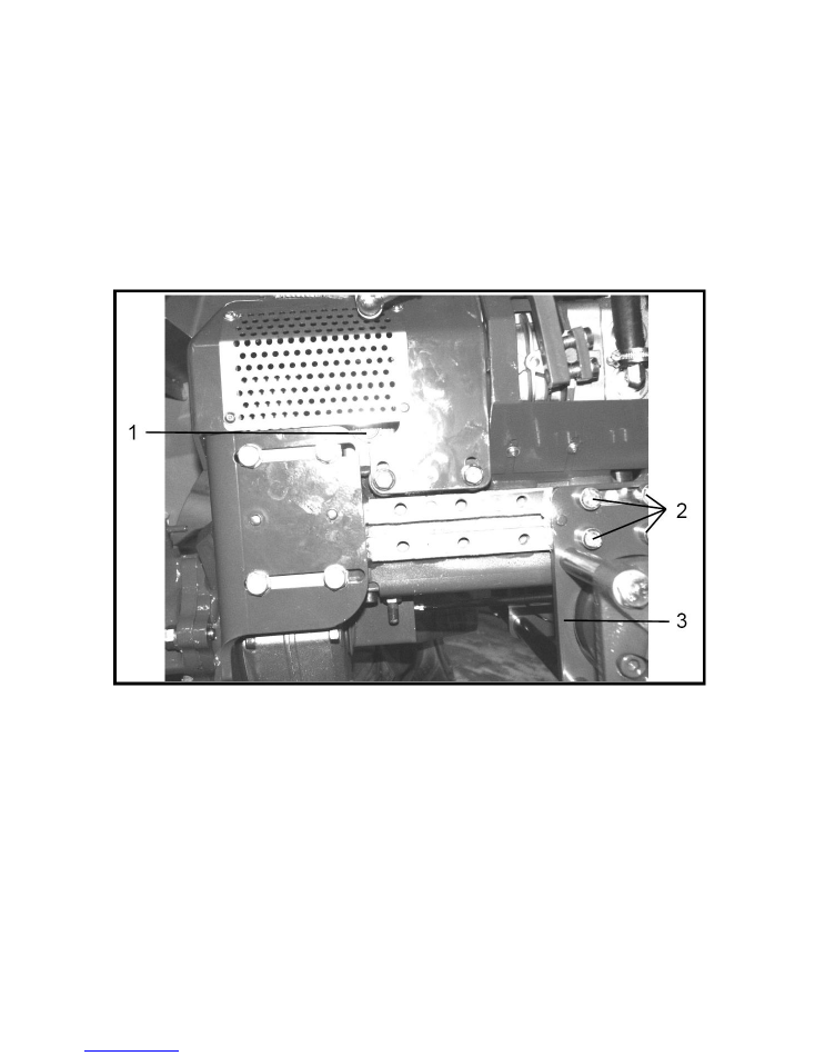
Figure 5
1 Grease nipples (2 x) beneath for steering
2 Oil tank ventilation
3 Hydraulic oil tank
4.Filling plug
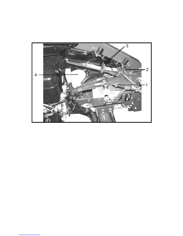
Figure 6
1 Adjusting screw for straight running (left and right to the machine)
2 Grease nipples (3 x) for steering
3 Adjusting nut for the 0 position
4 Hydraulic oil filters
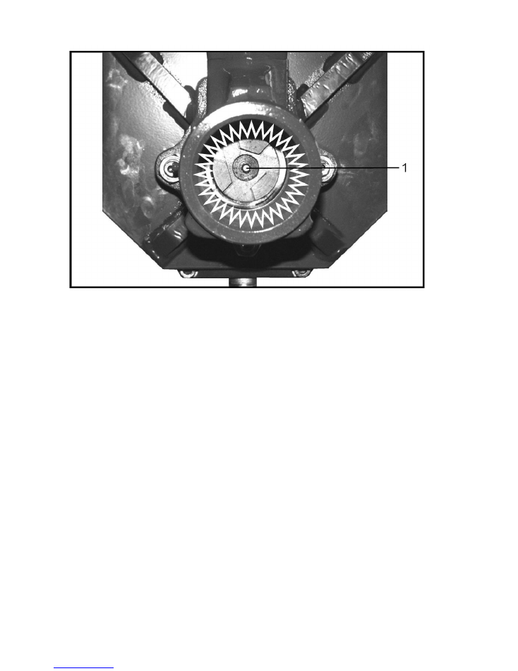
Figure 7
1 Grease nipple
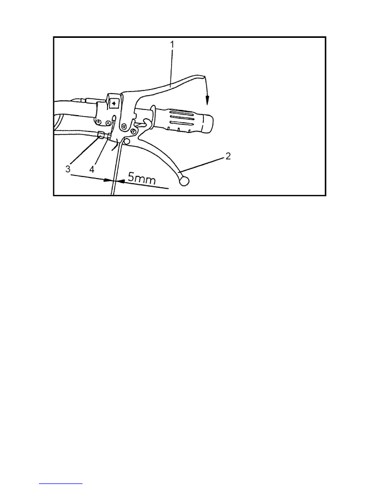
Figure 8
Maintenance:
General:
The
IRUS UNITRAK
was constructed so that it requires only a minimum of maintenance and upkeep. The
duration and efficiency of the machine depends upon conscientiously observing the instructions that
follow. (For the maintenance of the engine, please see the separate instructions for the engine.) All
maintenance and servicing activities are only to be performed with the engine off and the spark plugs
pulled.
After the first 8 hours of operation:
01. Change the engine oil.
02. Change the engine oil filter (only if the engine has an oil filter).
03. Retighten all hydraulic hose connections.
04. Tighten all other screw connections (engine mounting, axis adjustment, wheel motor suspension, etc.).
05. Check the hydraulic oil level.
06. Remove attachment, lubricate the attachment quick coupler with a grease brush, and mount
attachment again.
07. Lubricate the steering rod (3 grease-gun strokes per grease nipple [5 x]).
08. Check the zero position setting for the drive system.
09. Check and adjust coupler play (Fig. 8).

Daily:
01. Lubricate attachment quick coupling.
02. Check engine oil level (see separate manual for the engine).
03. Clean air filter, if necessary (see separate manual for the engine).
04. Check coupler play and adjust, if necessary (Figure 8).
Every 20 hours or sooner, if necessary:
01. Clean air filter (see separate manual for the engine).
02. Change engine oil (see separate manual for the engine).
03. Lubricate steering rod (3 grease gun strokes per grease nipple [5 x]).
04. Remove attachments and grease nipple at the PTO (3 grease-gun strokes) (Fig. 7/1)
After the first 50 hours of operation:
01. Remove casing and blow out the inside of the machine with compressed air.
02. Check hydraulic oil level.
03. Remove attachment, lubricate the attachment quick coupler with a grease brush, and mount
attachment again.
04. Lubricate steering rod (3 grease-gun strokes per grease nipple [5 x]).
05. Lubricate Bowden cables.
06. Check engine for leaks.
07. Change oil in the speed reduction gears (engine must be at operating temperature).
08. Replace hydraulic oil filter (Figure 6/4).
ATTENTION!
Collect waste oil in a suitable container and dispose of it according to the local recycling regulations. Never
allow oil to drain into the ground or into the sewer system.
Every 50 hours:
01. Remove casing and blow out the inside of the machine with compressed air.
02. Check the hydraulic oil level.
03. Remove attachment, lubricate the attachment quick coupler with a grease brush, and mount
attachment again.
04. Lubricate steering rod (3 strokes per grease nipple [5 x]).
05. Lubricate Bowden cables.
06. Check the engine for leaks
After every 500 hours, but at least 1 x per year:
01. Change the oil in the speed reduction gears (see "After the first 50 hours").
02. Change the hydraulic oil.
03. Replace the hydraulic oil filter.

Please note in particular:
Do not store machine in:
01.
Damp areas
02.
Outdoor areas
03.
In places where fertilizer is stored because in such cases it can cause severe rusting.
Store the machine in a place that is as dry as possible, protect from dust and the environment by covering
with a waterproof cover.
ATTENTION battery!
The built-in
IRUS UNITRAK
battery is completely maintenance free. Should it be necessary to charge the
battery, an approved gel battery charger must be used for charging.
IRUS - Motor Equipment GmbH • D-72393 Burladingen-Salmen things
Industrial area cottagers turf • Tel: +49 (0) 7126/928949-0 • Fax: -99
Internet: http://www.irus.de • Email: info@irus.de