Full Text Searchable PDF User Manual
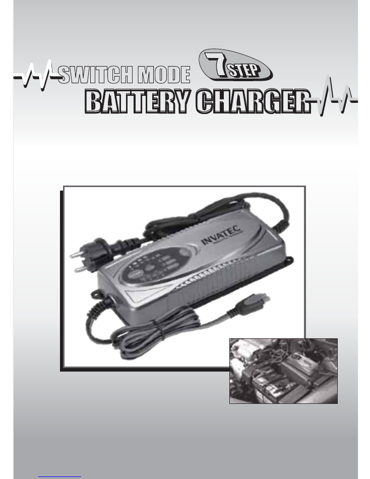
SC-7
For Lead acid batteries
14-230Ah (12V)
&
14-120Ah (24V)
BATTERY CHARGER
BATTERY CHARGER
SWITCH MODE
SWITCH MODE
User’s Manual And
Guide To
Professional Battery Charging
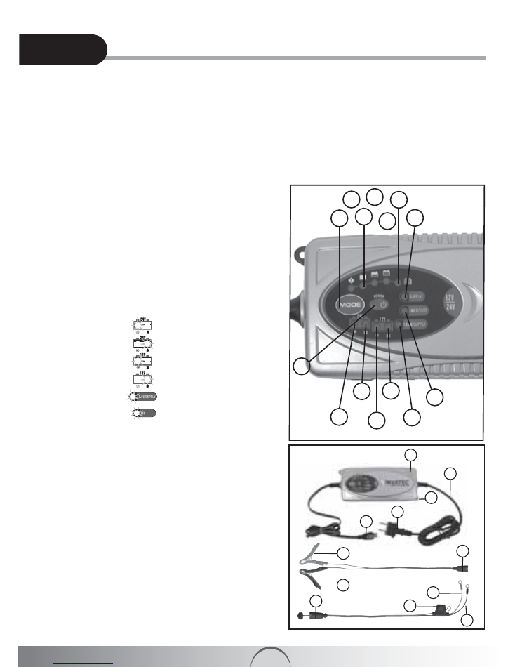
A1
1
13
2
3
4
5
6
Mode 5
Mode 6
Mode 4
Mode 3
Mode 2
Mode 1
9
14 10
11
12
8
7
15
17
19
18
24
20
25
26
22
21
23
16
Bulk Charging Time
....................................................8
Technical Data
.............................................................8
Charging Phases
.........................................................8
Diagnosis & Recovery.....................................9
Bulk.................................................................9
Absorption.....................................................10
Trickle Charge...............................................10
Maintenance Charge.....................................10
Supply 13.6V.................................................10
Boost 16V......................................................10
Error Mode
.................................................................10
Power Mode
...............................................................10
Trouble Shooting
.......................................................10
Maintenance
...............................................................11
Mounting & Product Dimensions
.............................11
Application
.................................................................11
Equipment
..................................................................11
Declaration of Compliance
.......................................11
Rescuing Drained Battery...................................7
Abnormality Protection........................................8
Overheating Protection.......................................8
Index
Index
For Your Safety
.................................................................2
Product Feature
................................................................2
Product Safety Feature
....................................................2
Contents
............................................................................2
Safety Information
............................................................2
Locate Charger
.................................................................3
Battery Type & Settings
...................................................3
Operation
....................................................................4 - 7
Charging..................................................................4
Equipment Description............................................4
Indication......................................................4 - 5
Component Description.....................................5
Select Charging Mode.............................................5
Reset/Deleting Settings...........................................5
Identification of Overlap Voltage.............................5
Charging Status Indication......................................6
Switching Over between different Modes................6
MODE 1 (28.8V/3.5A)..........................6
MODE 2 (29.4V/3.5A)..........................6
MODE 3 (14.4V/7A).............................6
MODE 4 (14.7V/7A).............................7
MODE 5 (13.6V/5A).............................7
MODE 6 (16V/1.5A).............................7
BOOST

A2
For Your Safety
This manual contains important safety and operating instructions. Read this manual carefully before using the charger for
the first time and keep the manual in a safe place for future reference.
Contents
1)
INVATEC
SC-7 Charger
2) Interchangeable quick contact battery leads with clamps
3) Interchangeable quick contact battery leads with eyelet terminals (Ø 6.3mm)
4) Plug-in fuse 10A
5) User Manual
Product Feature
Congratulations on your purchase of the
INVATEC
SC-7 7-Step fully automatic switch mode battery charger and
maintainer, designed for charging a variety of 12V and 24V Lead-Acid rechargeable batteries, widely used in boats,
cars, trucks and several other vehicles. The batteries may be of various types i.e. WET/Flooded (Liquid Electrolyte), GEL
(Gelatin type Electrolyte, absorbed into the plates), AGM (Absorbed Glass Mat), MF, VRLA (Valve Regulated Lead Acid)
batteries. Their capacity range from 12V/14Ah to 12V/230Ah and 24V/14Ah to 24V/120Ah. The
INVATEC
SC-7 battery
charger also charges batteries in cold conditions. Using state-of-the art technology, the charger enables the recharging
of the batteries to almost 100% of their original capacity. It recovers slightly sulphated batteries. It diagnoses and
rescues drained battery. It provides trickle charge and maintenance charging which increases battery life and gives
superb performance. The
INVATEC
SC-7 battery charger provides six output options to meet numerous requirements
i.e. 14.4V, 14.7V, 28.8V, 29.4V, 13.6V/SUPPLY and 16V/BOOST. It has 10 Stage charging strategy i.e. Pulse charge,
7.0A, 5.0A, 3.5A, 3.0A, 1.5A, 200mA, Boost charge, Maintenance & Power Supply. It has memory function. The charger
returns to last selected mode automatically when power is switched on (this feature is unavailable for 13.6V/SUPPLY
and 16V/BOOST mode). For repetitive charging process, this is a very useful feature. However different charging mode
could be selected by pressing the “MODE” button. It also features low back current drain and low ripple.
Product Safety Feature
•
Electronically safe against user errors. The charger will not damage vehicle electronics. It is totally safe for months-
long connections and maintenance of irregularly or seasonally used batteries even while the charger is still connected
to the vehicle. It provides optimal condition without damage.
No risk of over-charging!
•
Full protection against wrong connection and against short circuit ensures safe charging operation.
•
Provided with Spark protection mechanism. This feature does not activate when the charger is in Supply mode. The
charger will not begin operation upon connection to the battery unless charging mode has been selected. This
embedded feature eliminates the possibility of a spark that often appears during connections.
•
Fully controlled by internal MCU (Micro-Computer-Unit), which makes it faster, powerful, reliable and smarter. It detects
the state of charge of the battery plugged into it and initiates charging.
•
Dust and splash proof (IP65) approval. Approved for Outdoor use.
•
Double insulated
Safety Information
•
INVATEC
SC-7 charger is designed for charging 12V 14-230Ah and 24V 14-120Ah Lead-Acid rechargeable batteries. Do not use it for any other
purposes. It may cause an explosion.
WARNING! DO NOT ATTEMPT TO CHARGE A NON-RECHARGEABLE BATTERY (PRIMARY CELLS).
•
Before charging make sure the input power is as per rated specifications, otherwise the charging performance may be seriously affected.
•
Do not use battery charger for charging dry-cell batteries. They may burst and cause injury to persons and damage to property.
•
Never charge a frozen battery.
•
Never charge a damaged battery.
•
Do not use the charger with a damaged cable 17 . It must be replaced by the manufacturer, its service agent or similarly qualified technician in
order to ensure safety.
•
Do not operate charger if it appears to be damaged or malfunctioning. Take it to qualified person for inspection and repair.
•
Do not disassemble charger, incorrect reassembly may result in electric shock or fire. Locate charger as far away from battery as DC cable permit.
•
Never place charger above battery being charged, gases from battery will corrode and damage charger.
•
While charging always use safety glasses, gloves, protective clothing and keep your face away from the battery.
•
Remove metal items such as rings, bracelets, necklaces, and watches when working with a lead-acid battery. A lead-acid battery can produce a
short-circuit current high enough to melt such metallic objects, causing a severe burn.
•
Explosion hazard!
A battery being charged could emit explosive gasses. Avoid smoking or open sparks or flames in the vicinity of the battery.
Explosive and flammable substances such as fuel or solvents should not be kept in the vicinity of the charger or the battery.
•
Disconnect the supply before making or breaking connections to the battery.
•
While connecting the charger to the battery, maintain right polarity connection and avoid short-circuiting.
•
Connect the appropriate DC clip to the battery post which is not connected to the automobile chassis. (The battery terminal not connected to the
chassis has to be connected first.)
•
Connect the other DC connector to the chassis, away from the battery and fuel line.
•
The connector to be fixed to the positive pole shall be coloured red and that to be connected to the negative pole shall be coloured black.
•
Then connect the battery charger to the supply mains.
A3
Locate Charger
•
Locate the charger as far away from battery as the DC cord permits.
•
While charging do not place charger directly above or below the battery. Gases or fluids from the battery may corrode
and damage the charger.
•
Never allow battery acid to drip on the charger.
•
Charging should be carried out in a well-ventilated, weather protected facility.
Battery Type & Settings
The following recommendations should only be referred to as guidelines. For precise details, you must refer to battery
manufacturer for instructions.
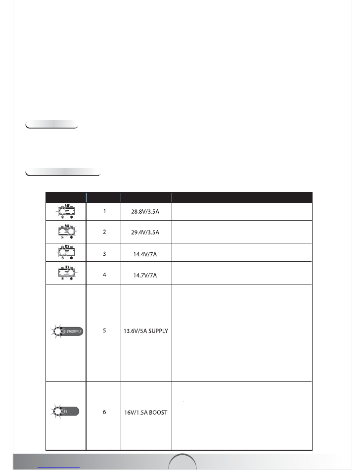
Symbol Mode Settings Details
This mode is normally suitable for 24V WET,
MF and GEL batteries.
This mode is recommended for several 24V
AGM batteries. It is also suitable for charging
batteries in sub-zero temperatures.
This mode is normally suitable for 12V WET,
MF and GEL batteries.
This mode is recommended for several 12V
AGM batteries. It is also suitable for charging
batteries in sub-zero temperatures.
a) Maintenance of 12V Lead-Acid rechargeable batteries:
This mode is suitable for maintenance of
12V batteries with capacity range from
14-230Ah. The charger delivers a constant
voltage of 13.6V. This is maintenance mode
for applications where maximum capacity
from the battery is required such as Golf
Carts, Floor Sweepers etc.
b) Power source:
INVATEC
SC-7 battery
charger is also used as a power supply,
without attaching a battery in this mode.
The charger delivers 13.6V/5A. Spark free
function is inactivated. However reverse
polarity protection function still works.
BOOST
This mode is mainly applied for recovering 12V
batteries with capacity range from 14-230Ah in
normal condition. To recover severely discharged
batteries due to stratified acid, this mode is useful.
High voltage (17V max) at 1.5A is applied for a
maximum period of 3 hours. A fully charged battery
gives faster result. High voltage may cause some
water loss. For optimal efficiency and minimum risk to
vehicle’s / boat’s electronics, battery must be
disconnected.
•
Do not cover the charger while charging.
•
Do not touch the battery clips together when charger is connected with mains.
•
After charging, disconnect the battery charger from supply mains. Remove the chassis connection and the battery connection, respectively. This
will reduce back drain current.
•
Charging must be ceased immediately if battery is found to be too hot or leaks out liquid during charging.
•
In case of malfunction or damage, immediately disconnect the charger from the mains.
•
Do not use vehicle when charging permanently installed batteries.
•
During charging the battery must be placed in a well ventilated area.
•
Danger of chemical burns!
Battery acid is highly corrosive. If your skin or eyes come into contact with acid, immediately rinse the affected part of
the body with excessive water and seek medical advice.
•
This appliance is not intended for use by persons (including children) with reduced physical, sensory or mental capabilities, or lack of experience
and knowledge, unless they have been given supervision or instruction concerning use of the appliance by a person responsible for their safety.
•
Children should be supervised to ensure that they do not play with the appliance.
•
Ensure that charger switches to maintenance charge mode, before it is left unattended and connected for long time. If this stage does not arrive
within 73 hours (max), the charger must be disconnected manually.
A4
OPERATION
Equipment Description
Charging
1) Charging of a permanently installed battery in a vehicle
a) Before connecting or disconnecting the battery leads, the power cord should be removed from the mains.
b) Check polarity of battery post. A positive (“+”) battery post usually has a larger diameter than a negative (“-”) post.
c) Identify the pole of battery which is connected to the chassis (earth). Normally the negative terminal is connected
to the chassis.
d) Charging of negative earthed battery:
• Make sure the black wire
㉖
(“-” pole connection) has not contact with the fuel line or the battery.
• Connect the red wire
㉕
(“+”) to the positive (“+”) pole of the battery and the black wire
㉖
(“-“) to the vehicle
chassis.
e) Charging of positive earthed battery:
• Make sure the red wire
㉕
(“+” pole connection) has no contact with the fuel line or the battery.
• Connect the black wire
㉖
(“-”) to the negative (“-”) pole of the battery and the red wire
㉕
(“+“) to the vehicle
chassis.
2) Charging of a battery not connected to a vehicle
a) Before connecting or disconnecting the battery leads, the power cord should be removed from the mains.
b) Connect the red wire
㉕
(“+”) to the positive (“+”) pole of the battery and the black wire
㉖
(“-“) to the negative (“-“)
pole.
In case of reverse polarity connection red LED
⑨
indicate error mode. This function would not work in
Supply Mode. Error indication light
⑨
would be also shown if charge mode is initiated without connecting the
battery to the battery leads.
3) Charging with eyelet terminals (Permanent connection to the vehicle battery)
a) Before connecting or disconnecting the battery leads, the power cord should be removed from the mains.
b) Connect the red wire
㉒
(“+”) to the positive (“+”) pole of the battery and the black wire
㉓
(“-“) to the negative
(“-“) pole.
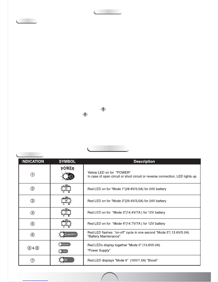
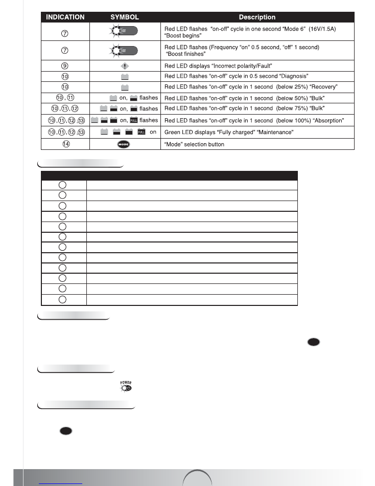
a) Indication:
BOOST
A5
b) Component Description
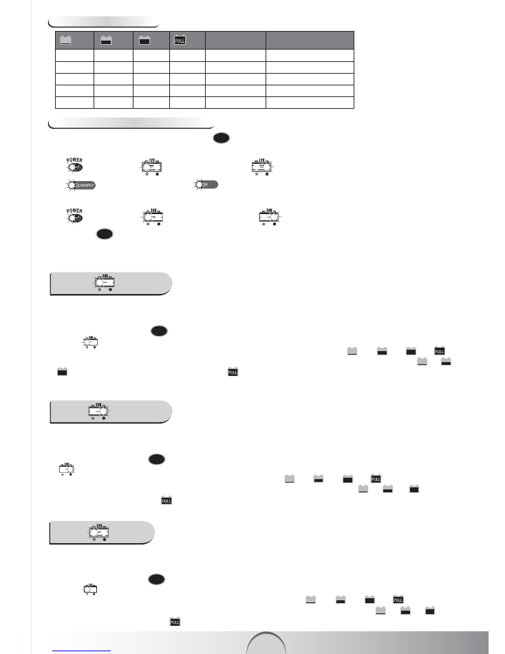
Reset / Deleting Settings
In beginning of charging process after connection to the power supply, the charger automatically resets itself to “Power”
basic settings and remains in
①
position unless further action is executed by the user. Yellow LED is lit.
Select Charging Mode
INVATEC
SC-7 battery charger has unique memory function. The charger returns to last selected mode automatically
when power is switched on. For repetitive charging process, this is a handy feature. However to charge various batteries
at different ambient temperature a specific charging mode could be selected manually by pressing the
⑭
selection
button until the light for correct voltage is lit. Within 0.5 second, the charger activates the selected mode.
MODE
Identification of Overlap Voltage
To treat a 14.6-21V±0.25V battery if it may be a fully charged 12V battery or deep-discharged 24V battery.
INVATEC
SC-7 charger smartly identifies correct nature of battery and provides appropriate course of action. Once the selection
button
⑭
is pressed, charging LED shall flash “on-off” cycle in 0.5 second. Within 1-2 minutes the embedded MCU
would detect change in battery voltage. If battery voltage remains at original value or rises to a higher level, system would
treat it as a 24V battery, if voltage falls, it is treated as a 12V battery. After correct identification, system would initiate
action as described in “a” or “b” under paragraph “Switching over between different Modes” until the battery is
disconnected.
MODE
Charger
Mounting Holes
Mains Cable
Power plug
Male connector
Female connector with protection cap
Fuse Holder with 10A plug-in fuse
“+” Pole connection cable (red) with ring terminal
“-” Pole connection cable (black) with ring terminal
Female connector
“+” Pole connection cable (red) with quick clamp (red)
“-” Pole connection cable (black) with quick clamp (black)
Indication Description
26
25
24
23
22
21
20
19
18
17
16
15
BOOST
BOOST
A6
MODE 1 (28.8V/3.5A)
This mode is suitable for charging 24V batteries with capacity range from 14-120Ah in normal conditions. Connect the
output terminals of the charger to the battery with right polarity. Connect the power cord to the power outlet to begin
charging.
Press the selection button
⑭
to select Mode 1 (LED 2). After executing this operation the corresponding LED
display
②
will light up. If no further process is activated, the electronic system will automatically start the
charging with a current of 3.5A ±10%. Charging shall continue in several stages:
⑩→
⑪→ ⑫→ ⑬
until
battery is fully charged upto 28.8V±0.25V. At this stage all intermediate charging status LEDs display
⑩
,
⑪
,
⑫
will turn on one by one until, LED display
⑬
will turn on. The Trickle current is now available to battery for
maintenance.
MODE
MODE 2 (29.4V/3.5A)
This mode is suitable for charging 24V batteries with capacity range from 14-120Ah in cold conditions or charging several
AGM batteries. Connect the output terminals of the charger to the battery with right polarity. Connect the power cord to
the power outlet to begin charging.
Press the selection button
⑭
to select Mode 2 (LED 3). After executing this operation the corresponding LED display
③
will light up. If no further process is activated, the electronic system will automatically start the charging with a
current of 3.5A ±10%. Charging shall continue in several stages:
⑩→
⑪→ ⑫→ ⑬
until battery is fully
charged upto 29.4V±0.25V. At this stage all intermediate charging status LEDs display
⑩
,
⑪
,
⑫
will turn on
one by one, until LED display
⑬
will turn on. The Trickle current is now available to battery for maintenance.
MODE
MODE 3 (14.4V/7A)
This mode is suitable for charging 12V batteries with capacity range from 14-230Ah in normal conditions. Connect the
output terminals of the charger to the battery with right polarity. Connect the power cord to the power outlet to begin
charging.
Press the selection button
⑭
to select Mode 3 (LED 3). After executing this operation the corresponding LED
display
④
will light up. If no further process is activated, the electronic system will automatically start the charging
with a current of 7.0A ±10%. Charging shall continue in several stages:
⑩→
⑪→ ⑫→ ⑬
until battery is
fully charged upto 14.4V±0.25V. At this stage all intermediate charging status LEDs display
⑩
,
⑪
,
⑫
will turn
on one by one, until LED display
⑬
will turn on. The Trickle current is now available to battery for maintenance.
MODE
If you press
⑭
, charging mode automatically switches to the next operation mode and begins functioning in that
specific mode. However after a full charge, if battery is not disconnected from the charger, it remains in float charge
mode, even if user switches it over to another mode. This protects battery from being damaged.
MODE
Switching over between different Modes
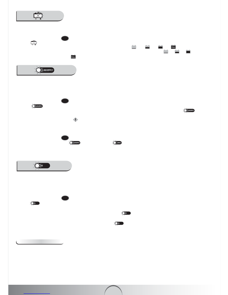
By repeatedly pressing the selection button
⑭
displays the charging modes in the following order-
a) for 12V battery:
① →
“Mode 3” (14.4V/7A)
→
“Mode 4” (14.7V/7A)
→
“Mode 5”
( 13.6V/5.0A)
→
“Mode 6” (16V/1.5A) and repeats this cycle.
① →
“Mode 1” (28.8V/3.5A)
→
“Mode 2” (29.4V/3.5A) and repeats this cycle.
b) for 24V battery:
BOOST
MODE
Charging Status Indication
FLASH OFF OFF OFF Below 25% Diagnosis & Recovery
ON FLASH OFF OFF Below 50% Bulk
ON ON FLASH OFF Below 75% Bulk
ON ON ON FLASH Below 100% Absorption
ON ON ON ON Full Maintenance
Charging Status Charging Phases
⑩ ⑪ ⑫ ⑬
A7
Rescuing Drained Battery
When charger is connected to a battery, before the start of charging process, the charger automatically detects the
voltage of the battery. If voltage is below 4.5V (for 12V battery) and 16V (for 24V battery) the
INVATEC
SC-7 charger will
not start due to its internal safety circuit. It initiates pulse charging mode if the voltage is in the range of 4.5V±0.25V to
10.5V±0.25V (for 12V battery) and 16V±0.25V to 21V±0.25V (for 24V battery). Once voltage of battery rises to
10.5V±0.25V (for 12V battery) or 21V±0.25V (for 24V battery) charger changes over to previously selected charging
mode. Now the battery can be charged faster and safely. Most drained batteries can be charged and used again using
this procedure.
MODE 4 (14.7V/7A)
This mode is suitable for charging 12V batteries with capacity range from 14-230Ah in cold conditions or charging several
AGM batteries. Connect the output terminals of the charger to the battery with right polarity. Connect the power cord to
the power outlet to begin charging.
Press the selection button
⑭
to select Mode 4 (LED 5). After executing this operation the corresponding LED
display
⑤
will light up. If no further process is activated, the electronic system will automatically start the charging
with a current of 7.0A ±10%. Charging shall continue in several stages:
⑩→
⑪→
⑫→
⑬
until battery is
fully charged upto 14.7V±0.25V. At this stage all intermediate charging status LEDs display
⑩
,
⑪
,
⑫
will turn
on one by one, until LED display
⑬
will turn on. The Trickle current is now available to battery for maintenance.
MODE
BOOST
MODE 5 (13.6V/5A)
a) Maintenance of 12V batteries :
This mode is suitable for maintenance of 12V batteries with a capacity range from
14-230Ah. The charger delivers a constant voltage of 13.6V. This is maintenance mode for applications where maximum
capacity from the battery is required such as Golf Carts, Floor Sweepers etc.
Connect the output terminals of the charger to the battery with right polarity. Connect the power cord to the power outlet
to begin charging.
Press the selection button
⑭
to select Mode 5 (LED 6). After executing this operation the corresponding LED
display
⑥
will light up. If no further process is activated, the electronic system will automatically start the
maintenance charging at constant voltage 13.6V±0.25V with a output current of 5.0A ±10% by indicating
⑥
flashing “on-off” cycle in one second. The charger has overload protection feature in this mode. If output voltage falls
below 4.5V, the charger returns to
⑨
mode.
b) Power Supply :
INVATEC
SC-7 battery charger is also used as a power supply, without attaching a battery in this
mode. The charger delivers 13.6V/5A. In this mode Spark free function is inactivated. However reverse polarity protection
still works.
Press the selection button
⑭
continuously for 3 seconds to select Mode 5 (LED 6). After executing this operation
the corresponding LED display
⑥
and LED display
⑧
will light up simultaneously. If no further process is
activated, the electronic system will automatically begin as a “Power Supply” with output voltage of 13.6V±0.25V and
output current of 5.0A ±10%
MODE
MODE
MODE 6 (16V/1.5A)
To recover severely discharged 12V batteries due to stratified acid with capacity range from 14-230Ah this mode is
applied. A fully charged battery gives faster result. High voltage may cause some water loss. For optimal efficiency,
battery must be disconnected.
Connect the output terminals of the charger to the battery with right polarity. Connect the power cord to the power outlet
to begin charging.
Press the selection button
⑭
to select Mode 6 (LED 7). After executing this operation the corresponding LED
display
⑦
will light up. If no further process is activated, the electronic system will automatically begin boost
function by delivering voltage 16.5V±0.25V with a output current of 1.5A ±20%. This stage is indicated by flashing
⑦
“on-off” cycle in one second. If battery is deep-discharged (4.5V),
⑦
may continue indicate upto 3 hours (max).
Recovery attempt is made at high voltage of 17V (max) at 1.5A. This process would terminate as soon as battery could
accept normal charging and it would be indicated by flashing
⑦
of with frequency of “on” 0.5 second, “off” 1
second.
BOOST
BOOST
BOOST
MODE
A8
BOOST
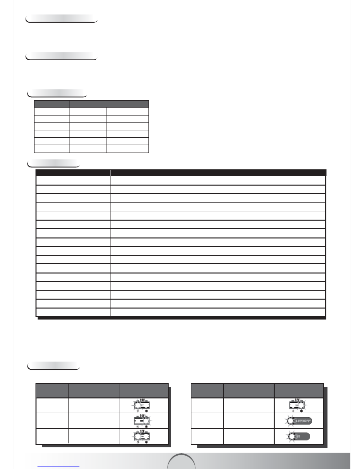
1 28.8V/3.5A
2 29.4V/3.5A
3 14.4V/7A
Abnormality Protection
In case of short-circuit, open circuit, reversed polarity connection or battery voltage below 4.5V±0.5V (for 12V battery) or
16V±0.25V (for 24V battery), the charger will turn-off the electronic system and will immediately reset the system back to
basic position to avoid damage to battery and charger.
Technical Data
Charging Phases
Bulk Charging Time
Overheating Protection
INVATEC
SC-7 charger is protected by NTC control. During the charging process, if the charger becomes too hot, the
power output is automatically reduced to protect itself from damage. The charger continues to work trickle charge.
Charger increases power automatically when the ambient temperature drops.
2.5 4.9
7.5 15
12 24
15 30
14
60
100
120
230 29
Battery Size For about 80% Charge (hours)
(Ah)
12V 24V
Input Voltage AC
Output Voltage
Input Current
Efficiency
Charging Voltage
Charging Current
Back Current Drain*
Ripple**
Ambient Temperature
Type of Charger
Type of Batteries
Battery Capacity
Dimensions (LxWxH)
Housing Protection
Weight
Noise Level
220-240VAC, 50/60Hz
12V & 24V (Auto-select)
1.5A RMS max
>75%
28.8V±0.25V or 29.4V±0.25V or 14.4V±0.25V or 14.7V±0.25V or 13.6V±0.25V or 16.5V±0.25V
7.0A±10% or 5.0A±10% or 3.0A±10% or 1.5A±20%
<5 mA
Max 150mV, 0.3A
-20°C to +50°C/-4°F to +122°F, Reduced output power at higher temperature
Seven step, fully automatic, switch mode with maintenance charging
12V & 24V Lead-acid batteries (WET, MF,AGM and GEL)
14-230 Ah (for 12V), 14-120Ah (for 24V)
201 × 91 × 51 mm
IP65 (Dust and Splash proof) Outdoor use
0.912 kg
<50 dB (Tested from a distance of 50cm)
MODEL SC-7
* = Back current drain is the amount of current drawn by the charger from battery, when the charger is connected to the battery, without
power cord connected.
INVATEC
SC-7 has extremely low back current drain which corresponds to 0.7 Ah per month (1mA/hr)
** = Ripple refers to interference of current and voltage. A high current ripple heats up battery and reduces life of battery. Against a
linear charger, which has a current ripple of upto 400%,
INVATEC
SC-7 charger’s current ripple is below 2% (0.15/12V or 0.3/24V
battery voltage) ,which is much lower than the max 5% for a sealed acid battery. Equipments connected to the battery could be
damaged by high voltage ripple.
MODE SETTINGS SYMBOL
MODE SETTINGS SYMBOL
4 14.7V/7A
5 13.6V/5A SUPPLY
6 16V/1.5A BOOST
INVATEC
SC-7 charger performs 7-step fully automatic charging cycle.
A9
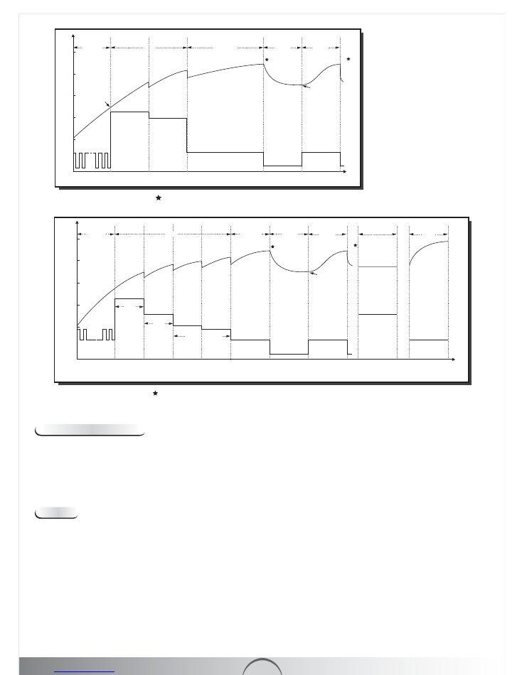
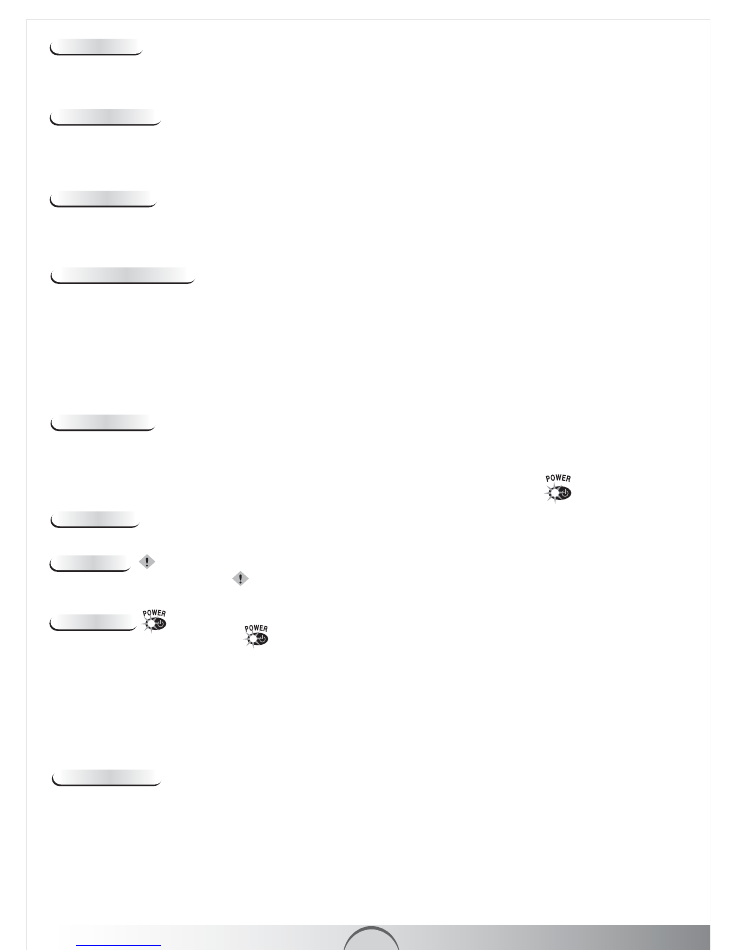
1) Diagnosis & Recovery:
As soon charging instruction is given to the charger, the unique diagnostic function
automatically checks status of battery (detects voltage). If a deeply discharged battery’s voltage is over 4.5V±0.5V (for
12V battery) or 16V±0.25V (for 24V battery), charger begins pulse charging with 3A high current and 1.5A low current to
recover it, which terminates when voltage reaches to 10.5V±0.25V (for 12V battery) or 21V±0.25V (for 24V battery). At
this stage or if voltage of a battery is over 10.5V±0.25V (for 12V battery) or 21V±0.25V (for 24V battery) at the beginning
of the process, the charger skips pulse charging and it switches over to pre-selected charging mode.
2) Bulk :
80% of energy is returned in this phase of charging. Here charger performs in multi-stages:
For 24V battery
a) High Rate Charging: Charger delivers constant current of 3.5A until the voltage reaches to 25.6V
b) Medium Rate Charging: Charger delivers constant current of 3.0A until the voltage reaches to 28.2V at which point
the charger switches to Absorption phase.
For 12V battery
a) High Rate Charging: Charger delivers constant current of 7.0A until the voltage reaches to 12.8V
b) Medium Rate Charging: Charger delivers constant current of 5.0A until the voltage reaches to 13.9V, at this level
constant current is 3.5A until voltage reaches to 14.0V. Finally charger delivers 3.0A current until voltage reaches to
14.1V at which point the charger switches to Absorption phase. Since current is not delivered at highest constant
level,
INVATEC
SC-7 charger will minimize the heating up of the battery, and hence will eliminate the build up of
gases. This ensures more efficient and safer performance.
* In case of cold weather charging, voltage refers to 29.4V, instead of 28.8V
SC-7 Battery Charging Curve (24V/3.5A)
Voltage(V)
Diagnosis &
Recovery
Bulk
Absorption
Trickle
Charge
High Rate
Charging
Medium Rate
Charging
16V
0
21.0V
25.6V
28.2V
28.8V
28.8V
3.5A
Pulse
Current (A)
Time
3.0A
1.5A
1.5A
Below
25.6V
Maintenance
Charge
* In case of cold weather charging, voltage refers to 14.7V, instead of 14.4V
Bulk
High Rate
Charging
Medium
Rate
Charging
Low Rate Charging
4.5V
14.0V
13.9V
5.0A
3.0A
3.5A
1.5A
1.5A
1.5A
5A
12.8V
10.5V
7.0A
14.1V
14.4V
13.6V
16.5V
14.4V
Pulse
Current (A)
Voltage(V)
0
Time
200mA
Below
12.8V
Maintenance
Charge
Supply
Diagnosis &
Recovery
Absorption
Trickle
Charge
Boost
SC-7 Battery Charging Curve (12V/7A)
1
1
1
2
2
2
A10
3) Absorption:
Use of a constant high current for extended periods of time risks gassing the battery. Therefore a
constant low charging current is given at 1.5A to raise voltage from 28.2V to 28.8V (for 24V battery) and 14.1V to 14.4V
(for 12V battery). In this phase complete charging up to almost 100% is achieved. Charger switches to trickle charge
phase after sensing that the battery is truly fully charged.
Standby feature :
When battery remains connected with vehicle’s wiring system, during the trickle mode, circuits
continuously monitor the current drawn by the battery.
5) Maintenance Charge :
As charger continuously monitors the terminal voltage in order to determine if a maintenance
charging should be initiated. If the battery is loaded and/or terminal voltage falls below 25.6V (for 24V battery) or 12.8V
(for 12V battery), the charger starts maintenance charging pulse at constant 1.5A until voltage reaches to 28.8V (for 24V
battery) or 14.4V (for 12V battery). Now maintenance charging is discontinued. Cycle of trickle charging and maintenance
charging is repeated indefinitely to keep battery in good condition when it is not in use and enables charger to be left
connected indefinitely.
NOTE:
If the charger is left connected indefinitely, check water levels every four weeks or as recommended by battery manufacturer to ensure
battery remains at proper level.
7) Boost 16V :
To recover severely discharged 12V batteries this mode is useful. High voltage (17V max) at 1.5A is
applied for a maximum period of 3 hours. At finish of this stage it would switch to normal charging setting (14.4V).
Trouble Shooting
Charger light does not turn on:
a) Remove the charger from the AC outlet and recheck the charger clamps are connected to the correct terminals
and are making a clean connection
b) Check to make sure AC outlet is supplying power
c) A bad connection of the battery to ground
Charger light is on but battery does not charge properly
a) The battery may be defective or of oversize
b) The battery has a excessive current draw, battery must be replaced
INVATEC SC-7
is fully interactive charger which adjusts itself to changing current and voltage requirement to charge and
maintain the battery.
4) Trickle Charge :
Battery is fully charged and ready to use. The battery will signal to the charger and will only take
enough current to sustain small loads such as alarms etc or current leaks in the vehicle wiring circuit. Very low current of
200mA is given to the battery. When voltage drops below 25.6V (for 24V battery) or 12.8V (for 12V battery), monitoring
circuit senses that battery needs more current to maintain its charge than available in trickle charge phase. The charger
switches to maintenance Charge phase.
6) Supply 13.6V : INVATEC
SC-7 charger provides a constant voltage at 13.6V and current upto 5.0A. This is suitable
for maintenance of 12V battery using Float charge approach at 100% of charge.
INVATEC
SC-7 battery charger is also
used as a power supply with maximum capacity of 13.6V/5A. In this mode spark free function is inactivated. However
reverse polarity protection function still works. It has electronic overload protection, which activates if output voltage from
the charger falls below 4.5V and current to around 6A (max). In this situation charger returns to
①
“Power” mode.
Power Mode
①
The charger goes to Power mode
①
in following situations-
a) Charger’s terminals are short circuited or open circuited when charging is initiated
b) Over-loaded charging
c) Attempt to charge a defective battery
d) Charging is initiated without any battery connected to the battery leads
e) Attempt to charge a battery whose voltage is below 4.5V±0.5V (for 12V battery) or 16V±0.25V (for 24V battery)
f) The charger is in recovery mode for over 7 hours
g) The charger is in bulk and absorption mode for over 41 hours
Error Mode
⑨
The charger goes to Error mode
⑨
in following situation-
a) The battery is connected with reverse polarity poles
A11
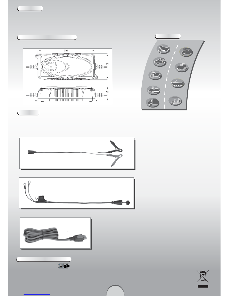
Interchangeable Quick Contact Battery Leads with Clamps
Connectors
Snap Connector
Interchangeable Quick Contact Battery Leads with Eyelet Terminals
Maintenance
INVATEC
SC-7 charger does not need any specific maintenance. Only install, maintain or service this charger
when it is disconnected from the mains. It may be cleaned with a dry cloth or soft tissue. Under any circumstances,
do not use any solvents or other cleaning agents.
Mounting & Product dimensions
The charger is easy to fix using two screws. Please refer to product drawing.
Equipment
INVATEC
SC-7 charger is supplied with two detachable and interchangeable colour coded lead sets- one with clamps for
bench charging and other with eyelet terminals (Ø6.3mm) with in-line battery protection plug-in fuse (10A) for permanent
attachment to the battery posts to allow quick connection/disconnection through snap-connector.
Declaration of Compliance
Tested and approved by and conforms to EN 60335-1, EN 60335-2-29, EN 55014-1, EN 55014-2, EN 61000-3-2,
EN 61000-3-3, EN 50366
Note: We reserve right to carry out technical modifications for improvement of SC-7 charger without notice.
Moto
rcycle
Golf Cart
Boa
t
Trac
tor
Car
A
TV
Sno
wmobile
T
ruck
R V
Application
67321