Full Text Searchable PDF User Manual
MODEL
Prod. Code - Order No.
STORED
DATE
DESIGNED
DATE
CHECKED
DATE
APPROVED
DATE
REV.
2
1
3
4
TOLERANCE
SCALE
UNIT
F
E
D
C
B
A
SHEET
1
20
DWG.
No.
TITLE
DF022-4PE-T1
2
1
3
4
F
E
D
C
B
A
CCD Color Camera
KP-HD20A/KP-HD1001/5 Series
Remote control protocol Specifications
(preliminary version)
Hitachi Kokusai Electric Inc.
-
Sep.11.9
(first edition)
Hirayama
Hirayama
SYMBOL
DATE
DESCRIPTION
(DRAWN) DESIGNED
00
KP-HD20A Remote
specification(RS-232C)
KP-HD20A Series
SHEET
2
10
DF022-4PE-S1
2
1
3
4
F
E
D
C
B
A
F
E
D
C
B
A
2
1
3
4
DWG.
No.
1) Comms* specifications
Sync system Start-stop sync
Bit rate
9600 bps
Data length
8 bits
Start bit
1
Stop bits
1
Parity
None
Bit transfer
LSB first
*Comms : Communications
*Comms : Communications
*Comms : Communications
*Comms : Communications
2) Comms control
The remote control software controls all communications. Data send/receive (BSC
handshake) is by transferring TEXT data to the camera controller chip.
3) Comms connection Scheme
Here is Comms connection Scheme. 3 lines System(Tx,Rx,GND) is applied
οΦà
RTS and CTS are not used
οΦâ
Serial Control
recitals
Tx
Sending
Rx
Reception
GND
Ground
4) Comms procedure
The following pages indicate the camera controller chip and remote control software
data protocol. In the description, the camera is designated as slave and the software
as master.
Receive protect timer (time out error)
The receive protect timer for master and slave processes is 1 second. For example,
if 1 block of TEXT data is being received, if the data interval exceeds 1 second,
error is produced and the data are lost. An acknowledgment of data receipt is not
produced.
( Caution )
( Caution )
( Caution )
( Caution )
The RS-232C conversion circuit is needed to connect a camera and a remote-controlled
machine (PC etc.) among. Please refer to the product specification for the output pin
on the camera side.
SHEET
3
10
DF022-4PE-S1
2
1
3
4
F
E
D
C
B
A
F
E
D
C
B
A
2
1
3
4
DWG.
No.
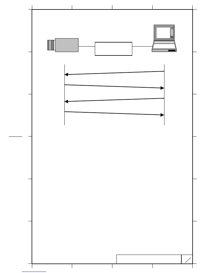
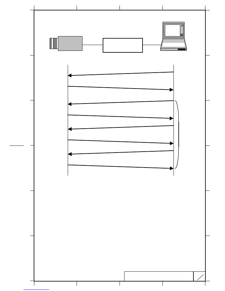
a)
Transmission from master (normal process)
1)
Session starts when ENQ is sent from master to slave.
2)
Slave acknowledges by returning ACK to master.
3)
Master sends data to slave.
4)
Slave acknowledges receipt of data by again returning ACK to master and end the
handshake.
Master
Slave
ENQ code (05H)
1)
ACK code (06H)
Transmit code (ASCII code)
2)
3)
4)
ACK code (06H)
RS
RS
RS
RS----232C
232C
232C
232C
conversion circuit
conversion circuit
conversion circuit
conversion circuit
SHEET
4
10
DF022-4PE-S1
2
1
3
4
F
E
D
C
B
A
F
E
D
C
B
A
2
1
3
4
DWG.
No.
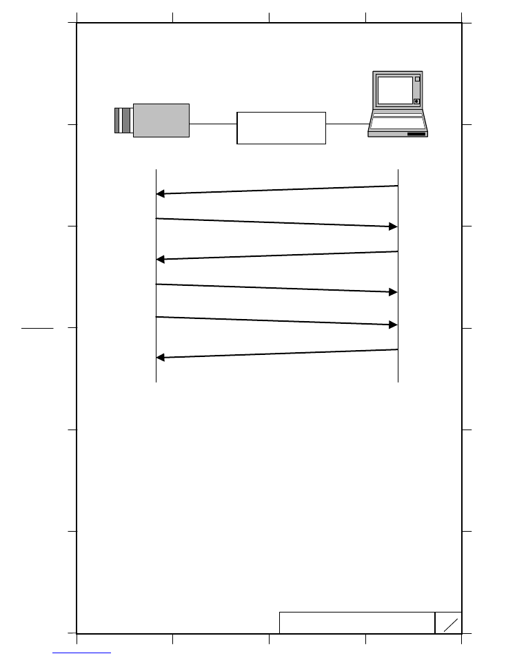
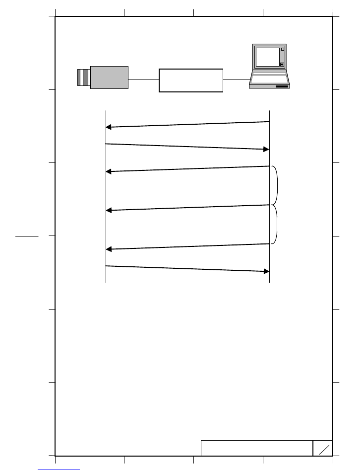
b)
Master reads data (normal process)
1) Session starts when ENQ is sent from master to slave.
2) Slave acknowledges by returning ACK to master.
3) Master sends read data command to slave.
4) Slave receives read data command, then acknowledges by returning ACK code to
master.
5) Slave sends read data to master.
6) Master receives read data, then acknowledges by returning ACK code to slave.
Master
Slave
ENQ code (05H)
1)
ACK code (06H)
Read command (ASCII code)
ACK code (06H)
2)
3)
4)
Read data (ASCII code)
ACK code (06H)
5)
6)
RS
RS
RS
RS----232C
232C
232C
232C
conversion circuit
conversion circuit
conversion circuit
conversion circuit
SHEET
5
10
DF022-4PE-S1
2
1
3
4
F
E
D
C
B
A
F
E
D
C
B
A
2
1
3
4
DWG.
No.
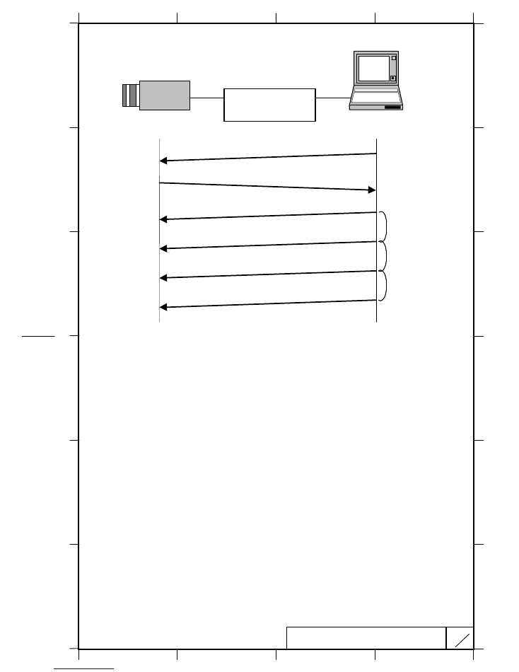
c)
Data transmitted by master (control abort process)
1) Master sends ENQ code to slave.
2) Since ACK code cannot be sent, slave sent NAK code to master.
3) Sequence is repeated 3 times in attempts to retransmit. After receiving the 3
rd
successive NAK code, comms control is aborted.
Master
Slave
ENQ code (05H)
1)
NAK code (15H)
2)
3)
ENQ code (05H)
NAK code (15H)
ENQ code (05H)
NAK code (15H)
ENQ code (05H)
NAK code (15H)
RS
RS
RS
RS----232C
232C
232C
232C
conversion circuit
conversion circuit
conversion circuit
conversion circuit
SHEET
6
10
DF022-4PE-S1
2
1
3
4
F
E
D
C
B
A
F
E
D
C
B
A
2
1
3
4
DWG.
No.
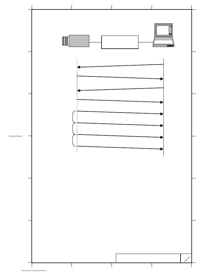
d)
Data transmitted by master (data error process)
1) Session starts when ENQ is sent from master to slave.
2) Slave acknowledges by returning ACK to master.
3) Master sends data, but error detected (framing, over-run error).
4) Slave detects error and does not accept data.
5) Sequence 3 and 4 repeats, then master transfers normal data.
6) Slave detects normal data and returns ACK code to master to end the session.
Master
Slave
ENQ code (05H)
1)
ACK code (06H)
2)
3)
Send data (error occurs)
ACK code (06H)
Send data (error occurs)
Send data (data normal)
4)
3 seconds elapse
3 seconds elapse
5)
6)
RS
RS
RS
RS----232C
232C
232C
232C
conv
conv
conv
conversion circuit
ersion circuit
ersion circuit
ersion circuit
SHEET
7
10
DF022-4PE-S1
2
1
3
4
F
E
D
C
B
A
F
E
D
C
B
A
2
1
3
4
DWG.
No.
e)
Data frame error (Master transmission)
1) Session starts when ENQ is sent from master to slave.
2) Slave acknowledges by returning ACK to master.
3) Master sends data.
4) For some reason, slave does not receive data.
5) Master does not receive acknowledgment to the send code and repeats the sequence
every 3 seconds for 3 times.
6) If unsuccessful after 3 attempts, master aborts the sequence and ends communication.
Master
Slave
ENQ code (05H)
1)
ACK code (06H)
2)
3)
Send data (ASCII code)
4)
3 seconds elapse
3 seconds elapse
5)
6)
Send data (ASCII code)
Send data (ASCII code)
Send data (ASCII code)
3 seconds elapse
RS
RS
RS
RS----232C
232C
232C
232C
conversion circuit
conversion circuit
conversion circuit
conversion circuit
SHEET
8
10
DF022-4PE-S1
2
1
3
4
F
E
D
C
B
A
F
E
D
C
B
A
2
1
3
4
DWG.
No.
f) Transmission frame error (Master receive)
1) Session starts when ENQ is sent from master to slave.
2) Slave acknowledges by returning ACK to master.
3) Master sends read command.
4) Slave returns ACK code to acknowledge read command.
5) Slave sends corresponding read data to master.
6) For some reason, master fails to receive read data.
7) Slave fails to receive acknowledgment of read data and attempts to resend every 3
seconds for 3 times.
8) After the third failure, slave aborts the sequence and ends communication.
Master
Slave
ENQ code (05H)
1)
ACK code (06H)
2)
3)
Read command (ASCII code)
4)
3 seconds elapse
5)
6)
ACK code (06H)
Read command (ASCII code)
Read command (ASCII code)
Raed command (ASCII code)
3 seconds elapse
3 seconds elapse
Read command (ASCII code)
7)
8)
RS
RS
RS
RS----232C
232C
232C
232C
conversion circuit
conversion circuit
conversion circuit
conversion circuit
SHEET
9
10
DF022-4PE-S1
2
1
3
4
F
E
D
C
B
A
F
E
D
C
B
A
2
1
3
4
DWG.
No.
5) Comms command Text data format
a) Send data and read command data (master to slave)
1) Command data are converted into ASCII code and transmitted.
2) Comms byte quantity is 18.
3) Comms data format (transmission sequence).
╆
Comms data description
οΫΞ
STX: Code indicating start of text. 1 byte (02H)
οΫΞ
Text data: Transmit / receive data. 14 byte (ASCII code)
οΫΞ
ETX: Code indicating end of text.
1 byte (03H)
οΫΞ
SUM: XOR result (FFH) of adding STX, Text data and ETX. 2 byte
Text data format details (transmission sequence).
╆
Text data details
οΫΞ
Status: Transmission data status. 2 bytes (ASCII code)
This parameter is used for selecting EEPROM write setting.
(0: write absent, 1: write present)
In Case of KP-HD20A, this parameter is ineffective because KP-HD20A
does not have an EEPROM.
οΫΞ
ID no.: Identification (camera ID) number is set by user. (2bytes
οΦö
ASCII code)
Please set ID no.to FFH because KP-HD20A does not have camera ID.
(FFH is global address and all data are changed)
οΫΞ
Area address: Sets number (0 to 255) for each adjustment item.
2 bytes (ASCII code)
οΫΞ
Relative no.: Sets number determined by each area address.
2 bytes (ASCII code)
οΫΞ
Data (note): Sets data to be transmitted. 2 bytes x 3 (ASCII code)
STX
Text data
ETX
SUM
18 bytes
Status
Area
address
Data
14 bytes
ID no.
Relative
no.
SHEET
10
10
DF022-4PE-S1
2
1
3
4
F
E
D
C
B
A
F
E
D
C
B
A
2
1
3
4
DWG.
No.
b) Read (receive) data (slave to master)
1) Command data are converted into ASCII code and transmitted.
2) Comms byte quantity is 10.
3) Comms data format (transmission sequence)
╆
Comms data description
οΫΞ
STX: Code indicating start of text. 1 byte (02H)
οΫΞ
Text data: Transmit / receive data. 6 byte (ASCII code)
οΫΞ
ETX: Code indicating end of text.
1 byte (03H)
οΫΞ
SUM: XOR result (FFH) of adding STX, Text data and ETX. 2 byte
4) Text data details (transmission sequence)
╆
Text data details (transmission sequence)
οΫΞ
Data (note): Sets data to be transmitted. 2 bytes x 3 (ASCII code)
STX
Text data
ETX
SUM
10 bytes
Data
6 bytes
KP-HD20A_COMMAND
CPU Ver.1.913
Command
Parameter
Area
ID
Data
ATW
0οΫ‰01
0οΫ‰04
0οΫ‰00
MANUAL
0οΫ‰01
0οΫ‰04
0οΫ‰02
PRESET
0οΫ‰01
0οΫ‰06
0x01
AGC
0οΫ‰01
0οΫ‰06
0οΫ‰00
3
One PushψÄÄAuto White
AWB
0οΫ‰01
0οΫ‰07
0οΫ‰01
1/30οΦà1/25οΦâ
0οΫ‰01
0οΫ‰08
0οΫ‰00
1/50
0οΫ‰01
0οΫ‰08
0οΫ‰01
1/100
0οΫ‰01
0οΫ‰08
0οΫ‰02
1/250
0οΫ‰01
0οΫ‰08
0οΫ‰03
1/500
0οΫ‰01
0οΫ‰08
0οΫ‰04
1/1000
0οΫ‰01
0οΫ‰08
0οΫ‰05
1/2000
0οΫ‰01
0οΫ‰08
0οΫ‰06
1/5000
0οΫ‰01
0οΫ‰08
0οΫ‰07
1/10000
0οΫ‰01
0οΫ‰08
0οΫ‰08
1/20000
0οΫ‰01
0οΫ‰08
0οΫ‰09
1/50000
0οΫ‰01
0οΫ‰08
0οΫ‰0A
AES
0οΫ‰01
0οΫ‰08
0οΫ‰10
1/1000
0οΫ‰01
0οΫ‰08
0x14
1/2000
0οΫ‰01
0οΫ‰08
0x15
1/5000
0οΫ‰01
0οΫ‰08
0x16
6
Image level
LEVEL
-128οΫû000 οΫû127
0οΫ‰01
0οΫ‰0C 0οΫ‰00οΫû0xFF
5
Whaite Balance Manual
RψÄÄGAIN
R GAIN
-128 οΫû000 οΫû127
0οΫ‰01
0οΫ‰0D 0οΫ‰00οΫû0xFF
7
Whaite Balance Manual
BψÄÄGAIN
B GAIN
-128 οΫû000 οΫû127
0οΫ‰01
0οΫ‰0E 0οΫ‰00οΫû0xFF
8
Pedestal
PEDESTAL
-28οΫû000 οΫû100
0οΫ‰01
0x10
0x64οΫû0xE4
OFF
0οΫ‰01
0x14
0x00
ON
0οΫ‰01
0x14
0x01
HIGH
0οΫ‰01
0x14
0x02
10
Detail
DETAIL
-128οΫû127
0οΫ‰01
0οΫ‰15
0οΫû255
11
Chroma
CHROMA
-128οΫû000 οΫû50
0οΫ‰01
0x16 0οΫ‰00οΫû0οΫ‰B2
OFF
0οΫ‰01
0οΫ‰1C
0οΫ‰00
No.1
0οΫ‰01
0οΫ‰1C
0x01
No.2
0οΫ‰01
0οΫ‰1C
0x02
No.3
0οΫ‰01
0οΫ‰1C
0x03
No.4
0οΫ‰01
0οΫ‰1C
0x04
No.5
0οΫ‰01
0οΫ‰1C
0x05
No.6
0οΫ‰01
0οΫ‰1C
0x06
No.7
0οΫ‰01
0οΫ‰1C
0x07
No.8
0οΫ‰01
0οΫ‰1C
0x08
No.9
0οΫ‰01
0οΫ‰1C
0x09
OFF
0οΫ‰01
0οΫ‰1D
0οΫ‰00
TOP
0οΫ‰01
0οΫ‰1D
0x01
BOTTOM
0οΫ‰01
0οΫ‰1D
0οΫ‰02
14
1 or 2 characters
0x01
0x1E
15
3 or 4 characters
0x01
0x1F
16
5 or 6 characters
0x01
0x20
17
7 or 8 characters
0x01
0x21
18
9 or 10 characters
0x01
0x22
19
11 or 12 characters
0x01
0x23
20
13 or 14 characters
0x01
0x24
21
15 or 16 characters
0x01
0x25
22
17 or 4 characters
0x01
0x26
23
3 or 4 characters
0x01
0x27
24
3 or 4 characters
0x01
0x28
OFF
0οΫ‰00
0οΫ‰01
0οΫ‰30
0οΫ‰00
WHITE GATE
0οΫ‰01
0οΫ‰01
0οΫ‰30
0οΫ‰01
ALC GATE
0οΫ‰02
0οΫ‰01
0οΫ‰30
0οΫ‰02
0/100
0οΫ‰01
0οΫ‰39
0x00
15/85
0οΫ‰01
0οΫ‰39
0x01
30/70
0οΫ‰01
0οΫ‰39
0x02
50/50
0οΫ‰01
0οΫ‰39
0x03
75/25
0οΫ‰01
0οΫ‰39
0x04
100/0
0οΫ‰01
0οΫ‰39
0x05
Gate display
25
Shutter Speed
12
Detection AreaοΦàALCοΦâ
Menu display
KP-D20A
2
Gain Mode
GAIN MODE
1
White Balance
MODE
Feature
SHUTTER SPEED
AES&LENS
9
Gamma
GAMMA
4
ALC GATE
οΦ©οΦ°οΦΑοΦΒοΦ¥
οΦΘοΦ®οΦΓοΦ≤οΦΓοΦΘοΦ¥οΦΞοΦ≤
13
TitleψÄÄMode
MODE
Peak/Average
PEAK/AVE
26
Page 1
KP-HD20A_COMMAND
CPU Ver.1.913
Command
Parameter
Area
ID
Data
Menu display
KP-D20A
Feature
OFF
0οΫ‰01
0οΫ‰3C
0οΫ‰00
No.1
0οΫ‰01
0οΫ‰3C
0x01
No.2
0οΫ‰01
0οΫ‰3C
0x02
No.3
0οΫ‰01
0οΫ‰3C
0x03
No.4
0οΫ‰01
0οΫ‰3C
0x04
No.5
0οΫ‰01
0οΫ‰3C
0x05
No.6
0οΫ‰01
0οΫ‰3C
0x06
No.7
0οΫ‰01
0οΫ‰3C
0x07
No.8
0οΫ‰01
0οΫ‰3C
0x08
No.9
0οΫ‰01
0οΫ‰3C
0x09
OFF
0οΫ‰01
0οΫ‰3E
0οΫ‰00
ON
0οΫ‰01
0οΫ‰3E
0οΫ‰01
OFF
0οΫ‰01
0οΫ‰40
0x00
MENU ON
0οΫ‰01
0οΫ‰40
0οΫ‰02
UP
0οΫ‰01
0οΫ‰40
0x10
DOWN
0οΫ‰01
0οΫ‰40
0x20
LEFT
0οΫ‰01
0οΫ‰40
0x80
RIGHT
0οΫ‰01
0οΫ‰40
0x40
30
CAMERA RESET
CAMERA RESET
0οΫ‰01
0x4F
0x00
OFF
0οΫ‰01
0x51
0οΫ‰00
ON
0οΫ‰01
0x51
0οΫ‰01
AUTO
0οΫ‰01
0x51
0οΫ‰02
32
WDR BLEND
WDR BLEND
128οΫû255
0οΫ‰01
0οΫ‰52 0οΫ‰80οΫû0οΫ‰FF
1/30οΦà1/25οΦâ
0οΫ‰01
0οΫ‰53
0οΫ‰00
1/50
0οΫ‰01
0οΫ‰53
0οΫ‰01
1/100
0οΫ‰01
0οΫ‰53
0οΫ‰02
1/250
0οΫ‰01
0οΫ‰53
0οΫ‰03
1/500
0οΫ‰01
0οΫ‰53
0οΫ‰04
1/1000
0οΫ‰01
0οΫ‰53
0οΫ‰05
1/2000
0οΫ‰01
0οΫ‰53
0οΫ‰06
1/5000
0οΫ‰01
0οΫ‰53
0οΫ‰07
1/10000
0οΫ‰01
0οΫ‰53
0οΫ‰08
1/20000
0οΫ‰01
0οΫ‰53
0οΫ‰09
1/50000
0οΫ‰01
0οΫ‰53
0οΫ‰0A
HD-SDI
0οΫ‰01
0οΫ‰57
0οΫ‰00
HD-VLC
0οΫ‰01
0οΫ‰57
0οΫ‰01
NORMAL
0οΫ‰01
0οΫ‰61
0οΫ‰00
SPECIAL
0οΫ‰01
0οΫ‰61
0οΫ‰01
36
MANUAL GAIN
PRESET GAIN
0οΫû48
0οΫ‰01
0οΫ‰68
0οΫ‰00οΫû0οΫ‰30
37
AGC LIMIT
AGC LIMIT
0οΫû48
0οΫ‰01
οΦêοΫ‰6A 0x06οΫû0οΫ‰30
OFF
0οΫ‰01
0οΫ‰98
0οΫ‰00
ON
0οΫ‰01
0οΫ‰98
0οΫ‰01
39
SLOPE1
0οΫû255
0οΫ‰01
0οΫ‰99 0οΫ‰00οΫû0οΫ‰FF
40
SLOPE2
0οΫû255
0οΫ‰01
0οΫ‰9A 0οΫ‰00οΫû0οΫ‰FF
41
POINT1
0οΫû255
0οΫ‰01
0οΫ‰9B 0οΫ‰00οΫû0οΫ‰FF
42
POINT2
0οΫû255
0οΫ‰01
0οΫ‰9C 0οΫ‰00οΫû0οΫ‰FF
43
VIDEO RENS Control
IRIS GAIN
0οΫû255
0x01
0οΫ‰A5 0οΫ‰00οΫû0οΫ‰FF
44
FILE1
0x01
0οΫ‰A7
0x00
45
FILE2
0x01
0οΫ‰A7
0x01
46
FILE3
0x01
0οΫ‰A7
0x02
47
FILE4
0x01
0οΫ‰A7
0x03
48
FILE5
0x01
0οΫ‰A7
0x04
FILE1
0οΫ‰01
0xA8
0οΫ‰00
FILE2
0οΫ‰01
0xA8
0x01
FILE3
0οΫ‰01
0xA8
0οΫ‰02
FILE4
0οΫ‰01
0xA8
0x03
FILE5
0οΫ‰01
0xA8
0x04
DC
0οΫ‰01
0xA9
0x00
VIDEO
0οΫ‰01
0xA9
0x01
1080i 59.94
0x01
0xAE
0x00
1080i 50
0x01
0xAE
0x01
1080p 29.97
0x01
0xAE
0x02
1080p 25
0x01
0xAE
0x03
27
White balance Area Select
WHITE GATE
28
Lens control
IRIS OPEN
29 CAMERA MENU OPERATION CAMERA MENU OPERATION
33
SHORT SHUTTER
SHORT SHUTTER
31
WDR MODE
WDR MODE
KNEE
KNEE
38
34
SDI OUTPUT
SDI OUTPUT
35
ATW RANGE
ATW RANGE
49
SCENE FILE SELECT
SCENE FILE SELECT
50
LENS TYPE
LENS TYPE
SCENE FILE SAVE
SCENE FILE SAVE
51
TV FORMAT
TV FORMAT
Page 2
KP-HD20A_COMMAND
CPU Ver.1.913
Command
Parameter
Area
ID
Data
Menu display
KP-D20A
Feature
4:3
0x01
0xAF
0x00
16:9
0x01
0xAF
0x01
PRESET
0x01
0οΫ‰C0
0οΫ‰00
VARIABLE
0x01
0οΫ‰C0
0οΫ‰01
54
HUE R
0οΫû255
0x01
0οΫ‰C1 0οΫ‰00οΫû0οΫ‰FF
55
HUE οΦΙ
0οΫû255
0x01
0οΫ‰C2 0οΫ‰00οΫû0οΫ‰FF
56
HUE G
0οΫû255
0x01
0οΫ‰C3 0οΫ‰00οΫû0οΫ‰FF
57
HUE C
0οΫû255
0x01
0οΫ‰C4 0οΫ‰00οΫû0οΫ‰FF
58
HUE οΦΔ
0οΫû255
0x01
0οΫ‰C5 0οΫ‰00οΫû0οΫ‰FF
59
HUE M
0οΫû255
0x01
0οΫ‰C6 0οΫ‰00οΫû0οΫ‰FF
60
SAT R
-
-
-
-
61
SAT οΦΙ
-
-
-
-
62
SAT G
1οΫû255
0x01
0οΫ‰C9 0οΫ‰01οΫû0οΫ‰FF
63
SAT C
1οΫû255
0x01
0οΫ‰CA 0οΫ‰01οΫû0οΫ‰FF
64
SAT οΦΔ
1οΫû255
0x01
0οΫ‰CB 0οΫ‰01οΫû0οΫ‰FF
65
SAT M
1οΫû255
0x01
0οΫ‰CC 0οΫ‰01οΫû0οΫ‰FF
VBS ASPECT
53
MASKING
MASKING
52
Aspect Ratio
Page 3