Full Text Searchable PDF User Manual

MUL
TIPOINT
1
Installation and User Instructions
for the
MULTIPOINT
10 and 15 litre Unvented Water
Heaters
HEATRAE SADIA
HEATRAE SADIA
HEATRAE SADIA
HEATRAE SADIA
HEATRAE SADIA
The quality name in water heating
Please read and understand these instructions before starting
work.
Please leave this leaflet with the user following installation
36 00 5718 Issue 4

2
Please read and understand these instructions prior to installing your Multipoint
unvented water heater. Particular attention should be paid to the section headed
IMPORTANT INSTALLATION POINTS
. Following installation and commission-
ing the operation of the heater should be explained to the customer and these instruc-
tions left with them for future reference.
TECHNICAL SPECIFICATIONS
Electrical rating ................................................... 2.75/3kW 230/240V
or .................................................................... 4.1/4.5kW 230/240V
Capacities ............................................................ 10 or 15 litres
Weight (full) ........................................................ 10 litre - 16.9kg
............................................................................. 15 litre - 23.8kg
Rated pressure ..................................................... 6 bar
Minimum recommended supply pressure ........... 0.8 bar
Temperature/Pressure Relief Valve ..................... 90
o
C/7 bar
1.0 IMPORTANT INSTALLATION POINTS
1.1
The Multipoint unvented water heater MUST be fitted with a Pressure Relief
Valve. The factory fitted Temperature/Pressure Relief Valve can fulfill this
function.
FAILURE TO PROVIDE ADEQUATE PRESSURE RELIEF
WILL INVALIDATE ANY GUARANTEE AND LEAD TO A DANGEROUS
INSTALLATION
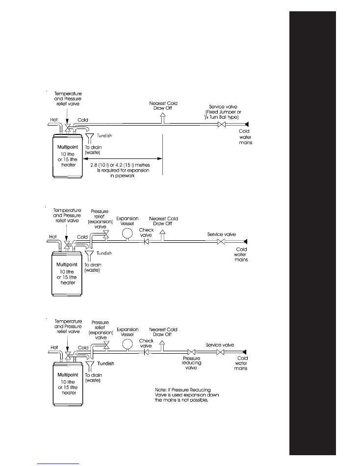
1.2
Expansion can take place within the cold water supply
PROVIDED THAT
BOTH
:
(a) Backflow in the main is not prevented by any stopvalve with loose jumper,
check valve, pressure reducing valve or similar,
AND
(b) Hot water expansion
does not
enter a branch to a cold water outlet (see
Diagram 1 for expansion pipe lengths).
N.B. Both the above conditions must be met. Additionally expansion within
the cold water supply will not be possible if the static supply pressure exceeds
4.1 bar (60p.s.i.).
1.3
If any of the conditions in 1.2 above cannot be met expansion must be
accomodated using an Expansion Vessel. To ensure all expansion takes place in
the vessel a Check Valve
must
also be fitted together with a Pressure (expansion)
Relief Valve (see Diagram 2). Use Accessory Pack U2 code no. 95 970 351.
1.4
If the static supply pressure exceeds 4.1 bar (60p.s.i.) a Pressure Reducing Valve
must be fitted to the cold main supply. If a Pressure Reducing Valve is used an
Expansion Vessel must also be used (see Diagram 3). Use Accesory Packs U1 and
U2 code no.’s 95 970 352 and 95 970 351.
MUL
TIPOINT
3
Diagram 1
For inlet pressures up to 4.1 bar (60 p.s.i.)
Diagram 2
For inlet pressures up to 4.1 bar (60 p.s.i.) where expansion
in main supply is not possible
Diagram 3
For inlet water pressures above 4.1 bar (60 p.s.i.)
WARNING: IF WATER FLOWS FROM THE PRESSURE RELIEF
VALVE OR TEMPERATURE/PRESSURE RELIEF VALVE THE
ELECTRICITY SUPPLY MUST BE SWITCHED OFF IMMEDI-
ATELY. CONTACT THE HEATRAE SADIA SERVICE TEAM
(Tel: 01603 420330) OR AN APPROVED INSTALLER.
4
2.0 INSTALLATION -
GENERAL REQUIREMENTS:
2.1
National Wiring rules may contain restrictions concerning the installation of
these units in bathrooms.
2.2
The unit should be vertically wall mounted using the wall bracket supplied. The
water connections must always be to the top of the unit.
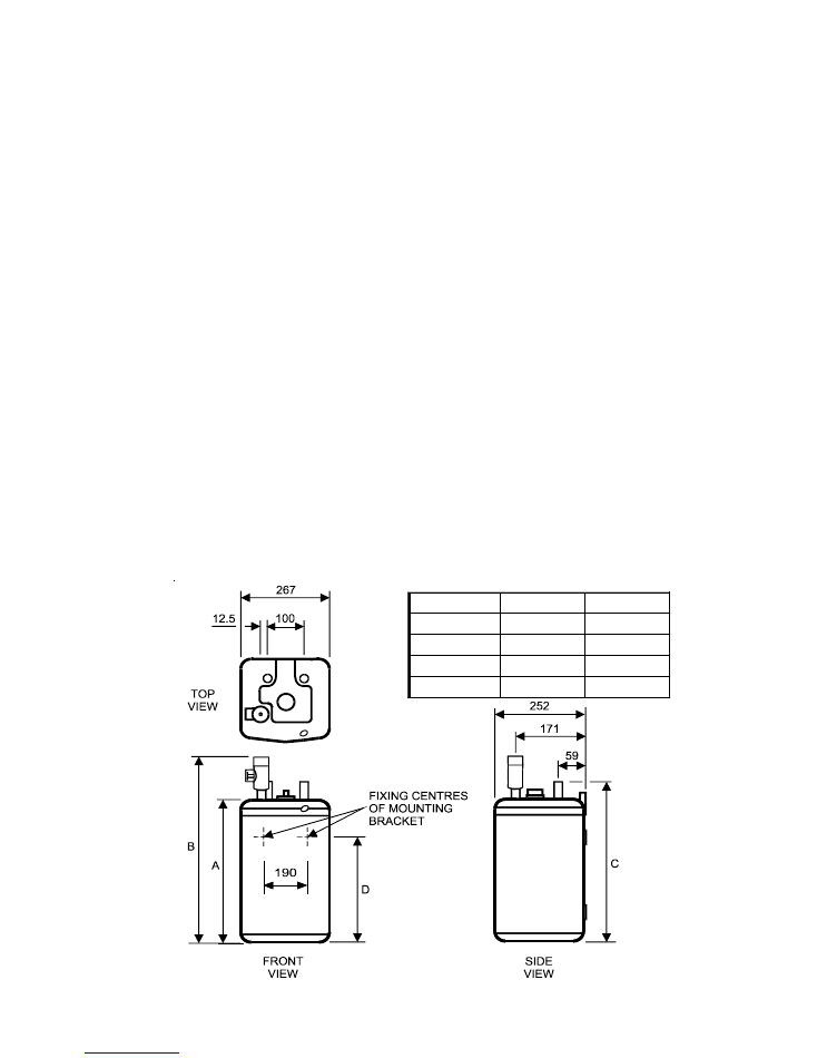
2.3
Enough space should be left at the top above the unit for pipe connections and
access to the Temperature/Pressure Relief Valve. Refer to Diagram 4 and the
Dimensions Table to determine a suitable position for the heater.
2.4
NOTE: Ensure that the wall can support the full weight of the unit (see TECHNI-
CAL SPECIFICATIONS) and that there are no hidden services (electricity, gas,
or water) below the surface of the wall.
2.5
DO NOT install where the unit may freeze.
2.6
Refer to the section IMPORTANT INSTALLATION POINTS to determine which
valves and accessories are required. Plumb in the valves in the sequence shown in
the relevant Diagrams 1 to 3.
2.7
The water connections are 15mm diameter copper tubes suitable for compression
fittings. Do not use solder joints as this will damage the heater and may prevent
servicing under warranty.
2.8
The INLET is marked BLUE, the OUTLET is marked RED. The WBS Listed
isolating valve (supplied) must be fitted on the cold water supply to the heater.
Several hot outlets can be served.
2.9
Plumbers Paste must not be used as it can impair the operation of the valves.
15 Litre
10 Litre
Dim ension
613
457
A
728
572
B
656
500
C
506
350
D
Diagram 4
MUL
TIPOINT
5
3.0 INSTALLATION -
ELECTRICAL REQUIREMENTS
WARNING: This appliance must be earthed. It is suitable for a.c.
supply only. Disconnect the electrical supply before removing the
terminal cover. Installation must be in accordance with the current
I.E.E. Wiring Regulations.
3.1
The unit is supplied fitted with a 0.75m 3 core 1.5mm
2
flexible
cable on the 3kW model or a 0.75m 3 core 2.5mm
2
cable on the
4.5kW model. The electicity supply should be fused 13 Amp for a
3kW model and 20 Amp for a 4.5kW model and be via a double
pole isolating switch with a contact separation of at least 3mm in
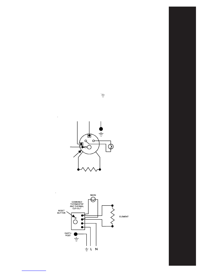
both poles. Refer to the schematic wiring diagrams below.
3.2
The wires are colour coded as follows:
Green and Yellow
EARTH
( )
Brown
LIVE
(L)
Blue
NEUTRAL (N)
NEON
ELEMENT
('Stat/Cut-out plugs
directly onto element
terminations)
COMBINED
THERMOSTAT
AND THERMAL
CUT-OUT
RESET
BUTTON
EARTH
POST
N
L
Wiring Diagram
3kW models
Wiring Diagram
4.5kW models

6
4.0 INSTALLATION -
DISCHARGE PIPE REQUIREMENTS
4.1
The discharge outlet from the Pressure (expansion) Relief Valve and the Tem-
perature/Pressure relief Valve must be connected to a discharge pipe. It is recom-
mended that the tundish supplied be installed in the discharge pipe to give a
visible indication that the valves are operating.
4.2
The discharge pipe must fall continuously from the valve outlets and be unob-
structed.
4.3
The pipe from the valves to the tundish should be 15mm o/dia minimum. From
the tundish to the point of discharge the pipe should be 22mm o/dia minimum
and have a resistance to flow equivalent to 9 metres of straight pipe. Long
discharge pipe runs should have an increased internal diameter.
4.4
The pipe material should be capable of conveying water/steam at 100
o
C.
4.5
The final discharge point should be in a safe, visible position.
5.0 COMMISSIONING
5.1
Do not switch on the electrical supply until the unit has been filled with water
and checked for leaks.
5.2
Check that all installation, electrical and discharge pipe requirements have been
met.
5.3
Check that all water and electrical connections are tight.
5.4
Open a hot water tap, turn on mains water supply to the heater.
5.5
Allow unit to fill and leave hot tap running for a short while to purge any air and
flush out the pipework. Close the hot tap and check the system for leaks.
5.6
Manually test the operation of the Temperature/Pressure Relief Valve and, if
fitted, the Pressure (expansion) Relief Valve. Ensure water flows freely from the
valve(s) and through the discharge pipes.
5.7
Switch on the electrical supply. The indicator light will illuminate during
heating. When the set temperature is reached the indicator light will go out.
5.8
The set temperature can be adjusted by rotating the knob located in the terminal
cover. It is possible to lock the thermostat knob in either the mid-range or a “hot”
position by following the procedures in 5.9 or 5.10 below. Always switch off the
electrical supply before removing the terminal cover.
5.9 Setting the “mid-range” position:
Rotate the thermosatat knob to the mid postion. Remove the terminal cover by
using a large flat bladed screwdriver to depress the three snap lugs located in the
three top rectangular depressions. Holding the thermostat knob in position turn
the terminal cover over and remove the backing disc from the underside of the

MUL
TIPOINT
7
cover. Turn the backing disc over and refit to the knob ensuring the
notch locates with the boss
on
the underside of the cover. Refit the
terminal cover, the thermostat will now be
locked in the “mid-
range” position.
5.10 Setting the “hot” position:
Rotate the thermostat knob to mid way through the hot graduated
range (red graphic). Follow the procedure detailed above, however
in this case the knob should be held in the “hot” position previously
set. When the terminal cover has been refitted the thermostat will be
locked in the “hot” position. This position is recommended when
using the heater in conjunction with a thermostatic blending valve.
6.0 MAINTENANCE - DESCALING
Little maintenance is required, however in hard water areas the unit will
require periodic descaling to ensure efficient operation. To descale the
unit:
6.1
Switch off and disconnect the electrical supply. Turn off the water
supply to the unit.
6.2
Open a hot tap to relieve any system pressure. Disconnect the
plumbing connections to the unit and remove from the wall bracket
(note full weights of units). Empty unit through the outlet connec-
tion.
6.3
Remove the terminal cover by using a large flat bladed screwdriver to
depress the 3 snap lugs located in the top 3 rectangular depressions.
6.4
Remove the plastic disc from the thermostat spindle. Remove the
insulating pad from the terminal housing. Disconnect the electrical
terminations to the thermostat. Disconnect earth links to the earthing
stud.
6.5
Remove the element plate assembly by unscrewing the five securing
screws, a tapped jacking point is provided. Remove any loose scale
from the container. Carefully clean off any scale from the element and
thermostat pocket. DO NOT clean scale from interior container walls.
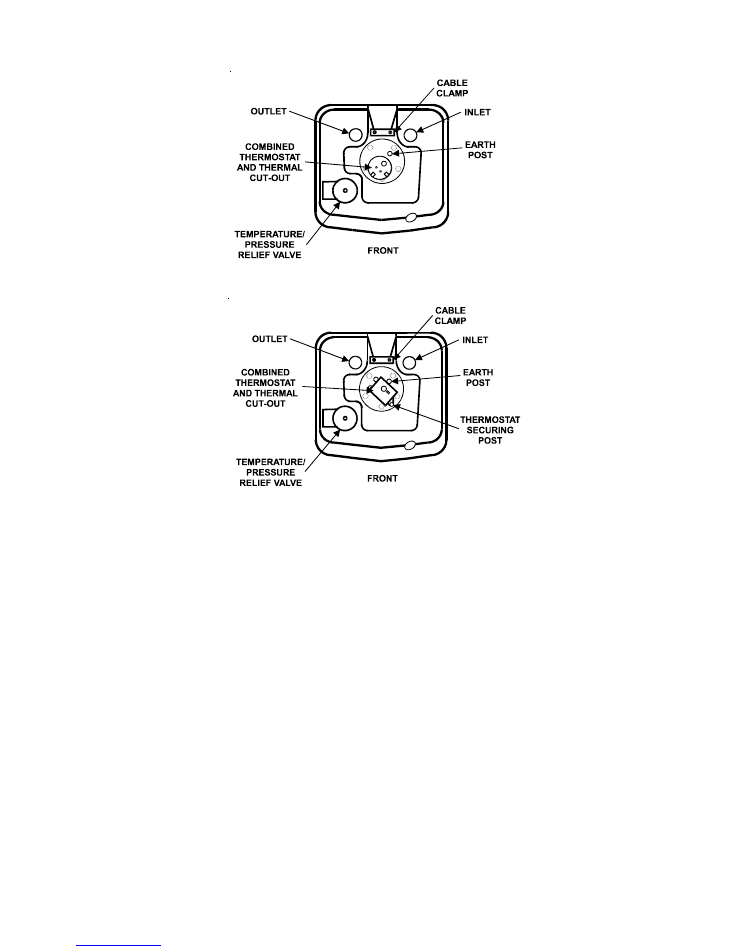
6.6
Re-assemble the element plate assembly fitting a new sealing gasket.
Note the correct orientation of the element plate by reference to
Diagram 5 overleaf. Rewire the unit with reference to the Wiring
Diagrams. Refit the insulating pad and plastic disc to ensure the
correct operation of the thermostat.
6.7
Re-commission the unit following the INSTALLATION and COM-
MISSIONING instructions.
8
7.0 MAINTENANCE - SAFETY VALVES
The Temperature/Pressure Relief Valve and, if fitted, the Pressure (expansion) Relief
Valve should be regularly checked. Manually operate the valves by either twisting the
cap or lifting the lever. Ensure water flows freely from the valve(s) and through the
discharge pipes. Ensure the valve(s) reseat correctly when released.
8.0 MAINTENANCE -
EXPANSION VESSEL PRECHARGE PRESSURE
The Expansion Vessel, if fitted, should have a precharge pressure of 4.1 bar (60
p.s.i.). This can reduce over time and eventually require re-charging. To do this:
8.1
Turn off water supply to the unit; open a hot tap to relieve system pressure.
8.2
Remove dust cap from top of Expansion Vessel
8.3
Check pre-charge pressure using a tyre pressure gauge. If the pressure is lower
than 4.1 bar (60 p.s.i.) it should be recharged using a tyre pump (Schraeder Valve
type). DO NOT OVER CHARGE.
8.4
Re-check pressure and when correct replace dust cap.
8.5
Turn on mains water supply and close hot tap.
Diagram 5
Correct orientation of element plate (viewed from top of unit)
3kW models
4.5kW models

MUL
TIPOINT
9
9.0 SPARE PARTS
The following comprehensive list of spare parts is available for your
Multipoint water heater. Please refer to the Rating Label on the side of
your heater before ordering to ensure the correct spare part is obtained.
DO NOT REPLACE WITH PARTS NOT RECOMMENDED BY
HEATRAE SADIA - THIS WILL INVALIDATE YOUR GUARANTEE AND
MAY RENDER THE INSTALLATION DANGEROUS.
DESCRIPTION
CODE NO.
Element plate assembly - 10 litre 3kW .................. 95 606 921
Element plate assembly - 15 litre 3kW .................. 95 606 922
Element plate assembly - 10 litre 4.5kW ............... 95 606 923
Element plate assembly - 15 litre 4.5kW ............... 95 606 924
Combined thermostat/thermal cut-out 3kW ......... 95 612 633
Combined thermostat/thermal cut-out 4.5kW ...... 95 612 634
Indicator light 3kW .............................................. 95 607 992
Indicator light 4.5kW ........................................... 95 607 993
Element plate gasket ............................................ 95 611 811
Pressure (expansion) Relief Valve ........................ 95 607 986
Temperature/Pressure Relief Valve ....................... 95 905 045
Check Valve .......................................................... 95 607 987
Expansion Vessel ................................................. 95 607 988
Pressure Reducing Valve ..................................... 95 607 989
Top cover moulding ............................................. 95 614 181
Terminal cover c/w thermostat knob .................... 95 614 182
10
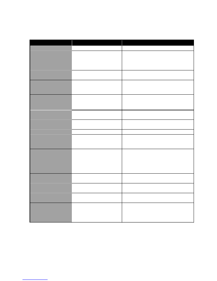
10.0 FAULT FINDING
Disconnect the electrical supply before removing the terminal cover. It is recom-
mended that any service operations on the Multipoint heater are carried out by a
competent person.
NOTE:
Use only Heatrae Sadia approved spare parts. Replacement of any parts with
components not recommended by Heatrae Sadia will invalidate the guarantee and
may render the installation dangerous.
ACTION
POSSIBLE CAUSES
FAULT
1. Check electrical supply
1. Electrical supply fault
Water not heating
WiringDiagram)
replace thermostat/thermal cut-out (see
check thermostat operation. If necessary
2. Check cut-out, if operated reset and
2. Thermal cut-out tripped
necessary
3. Check thermostat operation, replace if
3. Thermostat fault
POINTS)
U2 (see IMPORTANT INSTALLATION
Fit Pressure Reducing Valve Pack U1 and
pressure
Excessive mains water
(continuously)
Pressure Relief Valve
Discharge of water from
INSTALLATION POINTS)
1. Fit Pack U2 (see IMPORTANT
possible
1. Expansion in mains not
(intermittently)
Presure Relief Valve
Discharge of water from
2. Fit Packs U1 and U2
4.1 bar (60 p.s.i.)
2. Mains pressure exceeds
3. Fit Pack U2 when using Pack U1
Pack U2
3. Pack U1 fitted without
4. Replace Pressure Relief Valve
4. Pressure Relief Valve Fault
(see Section 8.0)
Expansion Vessel pre-charge pressure
5. Check and, if necessary, re-charge
Expansion Vessel
5. Loss of pressure from
Replace thermostat and thermal cut-out
cut-out fault
Thermostat and thermal
Pressure Relief Valve
water/steam from
Relief Valve and or
Temperature/Pressure
Discharge of water from
in accordance with flow direction arrows
1. Check all valves are correctly installed
fitted
1. Inlet valves incorrectly
No water flow
2. Check mains water supply is on
turned on
2. Mains water supply not
fitted check the strainer is not blocked
3. Check for obstructions. If Pack U1 is
supply
3. Blockage in mains water
while.
milkiness will disappear after a short
oxygen bubbles when flowing. The
Water from a pressurised system releases
Oxygenated water
"Milky" water

MUL
TIPOINT
11
11.0 ACCESSORIES
The heater can be used to supply several hot water outlets via conven-
tional taps. It is not recommended for supplying a shower. Individual site
demands should be considered when choosing capacity and the number
of outlets to be served.
A Thermostatic Blending Valve can be used in conjunction with this unit.
Accessory Pack U3 (code no. 95 970 354) is recommended. Follow the
installation instructions supplied with the valve for connection to the
system.
12.0 USER INSTRUCTIONS
12.1
The Multipoint unvented heater stores water at the temperature set
on the adjustable thermostat. This can be set to give temperatures
in the range of 10 to 70
o
C. To avoid any risk of freezing when the
heater is not in use for long periods during the winter months, do
not switch off the electrical supply and set the thermostat to its
minimum position. N.B. This will not protect other system pipework.
12.2
The thermostat can also be locked in either the mid range or a “hot”
(recommended when using in conjunction with a Thermostatic
Blending Valve) position. To lock the thermostat position the
instructions given under Sections 5.9 or 5.10 should be followed.
We recommend that this procedure is carried out by a qualified
electrician.
12.3
The indicator light will be illuminated when the unit is heating.
12.4
To ensure the heater continues to operate at its optimum perform-
ance it should be periodically maintained in accordance with the
instructions given under the Sections headed MAINTENANCE.
12.5 IMPORTANT NOTES TO USER
Do not block or restrict the discharge from any safety valve fitted.
Do not tamper with any safety valve fitted.
If water discharges from any safety valve fitted, switch off the
electrical supply to the unit immediately. Contact the Heatrae
Sadia Servive Team (Tel: 08701 600125) or an approved installer.
Do not turn the electrical supply on again until the unit has been
checked and approved by a qualified installer.
12
Guarantee
This water heater is guaranteed for a period of five years from the date of purchase
with the exception of the immersion heater and thermal controls which are guaranteed
for a period of two years provided:
1. The unit has been installed in accordance with these instructions and all necessary
inlet controls and safety valves have been fitted correctly.
2. Any valves or controls are of Heatrae Sadia recommended type.
3. The unit has not been tampered with and has been regularly maintained as detailed
in these instructions.
4. The unit has been used only for heating potable water.
5. Within 60 days of installation, the user completes and returns the certificate
supplied along with proof of purchase to register the product
The unit is not guaranteed against damage by frost and the immersion heater is not
guaranteed against excessive scale build up.
This guarantee does not affect the statutory rights of the consumer.
Envirnomental Information
This product is manufactured from many recyclable materials. At the end of its useful
life it should be disposed of at a Local Authority Recycling Centre to realise the full
environmental benefits.
Heatrae Sadia Heating
Hurricane Way Norwich NR6 6EA
www.heatraesadia.com
Main No:
01603 420100
Main Fax:
01603 420218
Sales:
01603 420110
Sales Fax:
01603 420149
Service:
08701 600125
Service Fax:
08701 600181