Full Text Searchable PDF User Manual
Digitaler High-Res 10-Kanal Signalprozessor mit
96 kHz / 32 Bit Signalweg
Digital High-Res 10-channel signal processor
with 96 kHz / 32 Bit signal path
deutsch / english
DSP PRO
MK2

15
Congratulations!
General instructions
Dear Customer,
Congratulations on your purchase of this innovative
and high-qual ity HELIX product.
With the HELIX DSP PRO MK2, Audiotec Fischer is
setting new standards in the range of digital signal
processors.
We wish you many hours of enjoyment with your
new HELIX DSP PRO MK2.
Yours,
AUDIOTEC FISCHER
General installation instructions for HELIX
components
To prevent damage to the unit and possible injury,
read this manual carefully and follow all installation
instructions. This product has been checked for
proper function prior to shipping and is guaranteed
against manufacturing defects.
Before starting your installation, disconnect
the battery’s negative terminal to prevent
GDPDJHWRWKHXQLW¿UHDQGRUULVNRILQMXU\
For
a proper performance and to ensure full warranty
coverage, we strongly recommend to get this prod-
uct installed by an authorized HELIX dealer.
Install your HELIX DSP PRO MK2 in a dry location
ZLWKVXI¿FLHQWDLUFLUFXODWLRQIRUSURSHUFRROLQJRIWKH
equipment. The signal processor should be secured
to a solid mounting surface using proper mounting
hardware. Before mounting, carefully examine the
area around and behind the proposed installa-
tion location to insure that there are no electrical
cables or components, hydraulic brake lines or any
part of the fuel tank located behind the mounting
surface. Failure to do so may result in unpredictable
damage to these components and possible costly
repairs to the vehicle.
General instruction for connecting the HELIX
DSP PRO MK2 signal processor
The HELIX DSP PRO MK2 signal processor may
only be installed in vehicles which have a 12 Volts
negative terminal connected to the chassis ground.
Any other system could cause damage to the signal
processor and the electrical system of the vehicle.
The positive cable from the battery for the entire
sound system should be provided with a main fuse
at a distance of max. 30 cm from the battery. The
value of the fuse is calculated from the maximum
total current draw of the car audio system.
Use only the provided connectors or the option-
ally available Easy Plug Cable for connection
of the HELIX DSP PRO MK2. The use of other
cables can result in damage of the signal pro-
cessor, the head unit / radio or the connected
DPSOL¿HUVORXGVSHDNHUV
Prior to installation, plan the wire routing to
avoid any possible damage to the wire harness.
All cabling should be protected against possible
crushing or pinching hazards. Also avoid routing
cables close to potential noise sources such as
electric motors, high power accessories and other
vehicle harnesses.
16
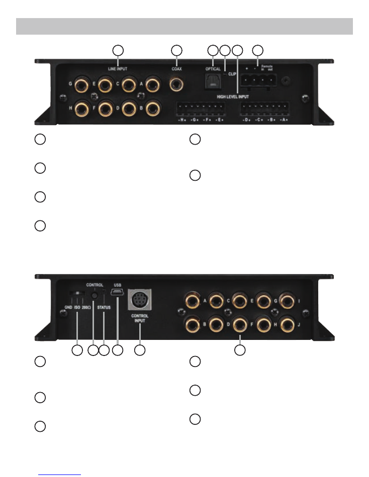
Connectors and control units
9
10
11
12
7
1
3
2
4
5
6
8
7
Ground lift switch
&DQ EH XVHG WR GH¿QH WKH FRQQHFWLRQ
between the grounding of the inputs and
outputs.
8
Control pushbutton
Use this button to either switch between the
setups or initiate a reset of the device.
9
Status LED
This LED indicates the operating mode of the
DSP and which setup has been chosen.
10
USB input
Connects the HELIX DSP PRO MK2 to your
PC.
11
Control Input
Multifunction interface for e.g. an optional
remote control or other HELIX accessory.
12
Line Output
/LQHRXWSXWVIRUFRQQHFWLQJDPSOL¿HUV0DNH
sure that the remote output is used to turn on
these devices.
1
Line Input
5&$ LQSXWV IRU FRQQHFWLQJ SUHDPSOL¿HU
signals.
2
Coax Input
Electrical input for digital stereo signals
(SPDIF format).
.
3
Optical Input
Optical input for digital stereo signals (SPDIF
format).
4
Clipping LED
This LED lights up red if one of the analog
inputs is overdriven.
5
Highlevel Input
Highlevel speaker inputs for connecting a
factory radio or an aftermarket radio without
pre-amp / line outputs.
6
Power Input
Connector for the DC power supply with an
additional remote in- and output. The remote
output has to be used to switch on external
DPSOL¿HUV

17
1
Line Input
FKDQQHO SUHDPSOL¿HU LQSXW WR FRQQHFW VLJQDO
sourc es such as radios. Input sensitivity is
factory-set set to 4 Volts. It is possible to vary the
sensitivity of each channel between 2 and 4 Volts.
inside the device.
2
Coax Input
Coaxial input in SPDIF format for connecting sour-
c es with a digital audio output. The sampling rate of
this input has to be in the range of 12 and 192 kHz.
The input signal is automatically adapted to the in-
ternal sample rate.
In order to activate this input and to control its vol-
ume, we recommend to use an optional remote
control.
Notice:
This signal processor can only handle ste-
reo input signals and no Dolby-coded digital audio
stream.
Important:
%HIRUH¿UVWXVHWKH
Coax Input
has to
be activated in the DSP PC-Tool software or with
an optional remote control. The
Optical Input
is
activated ex works.
3
Optical Input
Optical input in SPDIF format for connecting signal
sources with a digital audio output. The sampling
rate of this input must be between 12 and 96 kHz.
The input signal is automatically adapted to the
internal sample rate. In order to activate this input
and to control its volume, we recommend to use an
optional remote control.
Notice:
This signal processor can only handle ste-
reo input signals and no Dolby-coded digital audio
stream.
Notice:
,Q VWDQGDUG FRQ¿JXUDWLRQ WKH +(/,;
DSP PRO MK2 automatically activates this input if
a digital audio signal is detected.
4
Clipping LED
This LED lights up red if one of the eight
Line Inputs
or
Highlevel Inputs
is overdriven. The LED has no
function if the device is fed with digital input signals.
If this LED lights up reduce the input sensitivity by
using the internal trim potentiometers until the LED
goes out (item 3 page 20; “Adjustment of the input
sensitivity”).
5
Highlevel Input
8-channel highlevel loudspeaker input to connect
the signal processor directly to loudspeaker outputs
RI2(0DIWHUPDUNHWUDGLRVRU2(0DPSOL¿HUVWKDW
GRQRWKDYHDQ\SUHDPSOL¿HURXWSXWV,QSXWVHQVL
-
tivity is factory-set to 10 Volts for all channels.
It is possible to vary the sensitivity of each channel
between 5 - 10 Volts and 10 - 20 Volts inside the
device (item 3 page 20; “Adjustment of the input
sensitivity”).
By changing the sensitivity range, the input imped-
ance of the highlevel inputs is shifted as well in or-
der to guarantee a perfect operation in combination
ZLWK2(UDGLRVDQGKLJKSRZHU2(DPSOL¿HUV
Attention:
Solely use the pluggable screw-terminal
for the highlevel connector which is included in de-
livery or an optional available cable harness from
the HELIX accessory assortment!
Important:
It is strictly forbidden to use the
High-
level Input
DQG SUHDPSOL¿HU LQSXWV
Line Input
) at
the same time. This may cause severe damage to
WKHSUHDPSOL¿HURXWSXWVRI\RXUFDUUDGLR
6
Power Input
This input is used for connecting the signal pro-
cessor to the power supply of the vehicle and for
remote in / out. If the highlevel loudspeaker inputs
are used the remote input can be left unconnected.
The remote output is used for turning on/off ampli-
¿HUVWKDWDUHFRQQHFWHGWRWKH
Line Outputs
of the
HELIX DSP PRO MK2. Connect this remote out-
SXW WR WKH UHPRWH LQSXWV RI \RXU DPSOL¿HUV 7KLV
is
essential to avoid any interfering signals. The
remote output is
activated automatically as soon
as the booting process of the DSP is completed.
Additionally this output will be turned off during the
“Power Save Mode” or a software update process.
Attention:
Solely use the pluggable screw-terminal
which is included in delivery!
Important: Never use a different signal than the
remote output of the DSP to activate connected
DPSOL¿HUV
7
Ground lift switch
The ground of the HELIX DSP PRO MK2 signal in-
puts is galvanically decoupled from the ground of
the signal outputs. In many cars this setup is the
best way to avoid alternator noise.
Nevertheless, there are use cases where it will
Initial start-up and functions

be necessary to directly connect input and output
ground or to tie both grounds together via a resistor.
Therefore the
Ground lift switch
has three positions:
- center position: input and output ground
separated.
-
left
position: input and output ground tied
together.
- right position:
input
and
output
ground
connected via 200 Ohms resistor.
8
Control pushbutton
The
Control pushbutton
allows the user to switch
between the two setup memory positions. To switch
between the setups the button has to be pressed
and held for one second. Switching is indicated by
DVLQJOHUHGÀDVKRIWKH
Status LED
. Pressing the
EXWWRQIRU¿YHVHFRQGVFRPSOHWHO\HUDVHVWKHLQWHU
-
QDOPHPRU\7KLVLVLQGLFDWHGE\DFRQVWDQWÀDVKLQJ
of the
Status LED
.
Attention:
After erasing the setups from memory
the HELIX DSP PRO MK2 will not reproduce any
audio output.
9
Status LED
The
Status LED
indicates the current active DSP
setup. Green means that setup 1 is load ed, orange
PHDQVWKDWVHWXSLVORDGHG$ÀDVKLQJUHGOLJKWLQ
-
dicates that no setup is loaded. In that case please
load a new setup via the DSP PC-Tool software. If
the LED starts blinking orange, the internal tem-
SHUDWXUHSURWHFWLRQLVDFWLYH$W¿UVWWKHUHPRWHRXW
-
put will be turned off. If the temperature still rises the
signal processor will shut down until it has reached
a safe temperature level again.
10
USB input
Connect your personal computer to the
DSP PRO MK2 using the provided USB cable.
7KH UHTXLUHG 3& VRIWZDUH WR FRQ¿JXUH WKLV VLJQDO
processor can be downloaded from the Audiotec
Fischer website
ZZZDXGLRWHF¿VFKHUFRP
.
Please note:
It is not possible to connect any USB
storage devices.
11
Control Input
This multi-functional input is designed for HELIX ac-
cessory products like a remote control which allows
to adjust several features of the signal processor.
'HSHQGLQJRQWKHW\SHRIUHPRWHFRQWURODW¿UVWLWV
IXQFWLRQDOLW\KDVWREHGH¿QHGLQWKH³'HYLFH&RQ
-
¿JXUDWLRQ0HQX´RIWKH'633&7RROVRIWZDUH
12
Line Output
FKDQQHO SUHDPSOL¿HU RXWSXW IRU FRQQHFWLQJ
SRZHUDPSOL¿HUV7KHRXWSXWYROWDJHLV9ROWVPD[
Please make sure that you always turn on/off exter-
QDODPSOL¿HUVXVLQJWKHUHPRWHRXWSXWRIWKHVLJQDO
processors
Power Input
. Never directly control the
external amps by a signal from the ignition switch
of your car! Additionally this output will be turned
off when the “Power Save Mode” of the signal pro-
cessor is active. The outputs can be assigned to
any of the inputs as desired using the DSP PC-Tool
software.
18
Initial start-up and functions
Channel A
Channel B
Channel C
Channel D
Channel E
Channel F
Channel G
Channel H
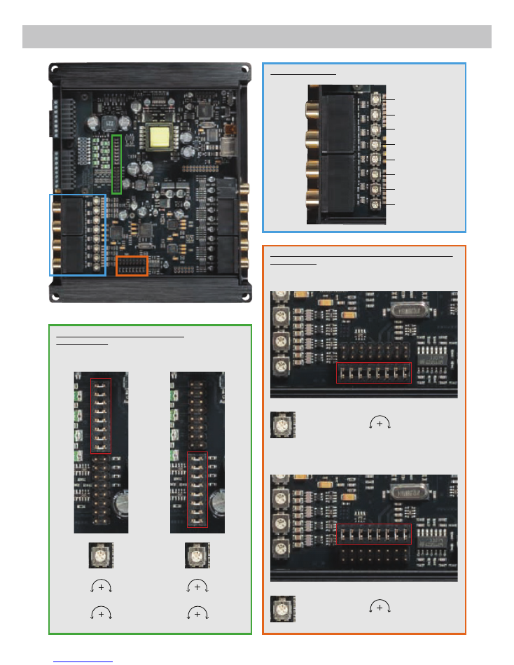
Channel assignment:
Adjustment of the input sensitivity of the
highlevel inputs:
Jumper upper position*
Jumper lower position
2 V 4 V*
5 V 10 V*
RCA / Cinch
2 V 4 V
Highlevel
10 V 20 V
Adjustment of the input sensitivity for using channel G & H
as AUX inputs:
Jumper lower position*
Channel G & H:
2 V 4 V*
Jumper upper position
Channel G & H:
250 mV 500 mV
19
Installation
* Ex factory adjustment of HELIX DSP PRO MK2
Fig. 1
Fig. 3
Fig. 2

20
Installation
Connection of HELIX DSP PRO MK2 to the head
unit / car radio:
Caution:
Carrying out the following steps will re-
quire special tools and technical knowledge. In or-
der to avoid connection mistakes and / or damage,
ask your dealer for assistance if you have any ques-
tions and follow all instructions in this manual (see
page 15). It is recommended that the device will be
installed by an authorized HELIX dealer.
&RQQHFWLQJWKHSUHDPSOL¿HULQSXWV
Use the correct cable (RCA / cinch cable)
WR FRQQHFW WKHVH LQSXWV WR WKH SUHDPSOL¿
-
er / lowlev el / cinch outputs of your car radio.
Each input can be assigned to any output us-
ing the DSP PC-Tool software. The automatic
turn-on circuit does not work when using the
SUHDPSOL¿HULQSXWV,QWKLVFDVHWKHUHPRWHLQ
-
put has to be connected to activate the HELIX
DSP PRO MK2.
Important:
It is strictly forbidden to use the
Highlevel Input
DQG SUHDPSOL¿HU LQSXWV
Line
Input
) at the same time. This may cause severe
GDPDJHWRWKHSUHDPSOL¿HURXWSXWVRI\RXUFDU
radio.
2. Connecting the highlevel speaker inputs
The highlevel loudspeaker inputs can be con-
nected directly to the loudspeaker outputs of an
OEM or aftermarket radio using appropriate ca-
bles (loudspeaker cables with 1 mm² / AWG 18
max.). We recommend the following channel
assignment if a common car radio will be con-
nected to the signal processor:
Channel A = Front left
Channel B = Front right
Channel C = Rear left
Channel D = Rear right
Actually it is not mandatory to use all high level
speaker inputs. If only two channels will be con-
nected we recommend to use the channels A
and B. Make sure that the polarity is correct. If
one or more connections have reversed polar-
ity it may affect the performance of the signal
processor. If this input is used the remote input
does not need to be connected as the signal
processor will automatically turn on once a
loudspeaker signal is received.
$GMXVWPHQWRIWKHLQSXWVHQVLWLYLW\
Attention:
It is mandatory to properly adapt
the input sensitivity of the DSP PRO MK2 to
the signal source in order to avoid damage
to the signal processor.
If you want to change the input sensitivity you
KDYHWRRSHQWKHGHYLFHDW¿UVW'LVPDQWOHWKH
side panel where the USB input is located by
UHPRYLQJ WKH ¿YH 3KLOOLSV VFUHZV DQG SXOO RXW
the bottom plate sideways. Now you have ac-
cess to the eight trim potentiometers that allow
adjusting each channel individually. The assign-
ment of the trim pots to the respective channels
LVVKRZQLQ¿JXUHRQSDJH
Please note:
The setting of the trim potentiom-
eters affects both the lowlevel and the highlevel
inputs!
If the sensitivity range of the highlevel input may
QRWEHVXI¿FLHQWLWLVSRVVLEOHWRFKDQJHLWE\UH
-
SRVLWLRQLQJDMXPSHUVHH¿JXUHRQSDJH
7KHVHQVLWLYLW\UDQJHRIWKHWZRSUHDPSOL¿HULQ
-
puts G and H can also be changed to connect
HYHQ PRELOH GHYLFHV ZLWK VLJQL¿FDQWO\ ORZHU
output voltage (like smartphones) by reposition-
LQJDIXUWKHUMXPSHUVHH¿JXUHRQSDJH
Important:
To change the position of a jumper it
has to be removed by pulling it straight upwards
and plugged into the desired position. Make
sure that the jumper is reinserted properly and
all pins are fully inserted. The position of each
jumper can be changed independently.
Follow the subsequent steps to perfectly adapt
the signal processors input sensitivity to your
audio source by using the internal trim poten-
tiometers:
'RQµWFRQQHFWDQ\DPSOL¿HUVWRWKHRXWSXWV
of the HELIX DSP PRO MK2 during this
setup.
2. Turn on the signal processor.
3. Adjust the volume of your radio to approx.
90 % of the max. volume and playback an
1 kHz full scale test tone (0 dB) via CD drive.
4. The adjustment will be easier when you con-
nect and adjust one input channel after the
other.
5. If the
Clipping LED
already lights up, you
have to reduce the input sensitivity via the
respective trim potentiometer until the LED
turns off.

21
If the potentiometer is already set to full CW
position it will be necessary to change the
sensitivity range by repositioning the jumper
VHH¿JXUHRQSDJH1RWHWKDWWKLVZLOO
only have an effect on the highlevel inputs!
6. Increase the input sensitivity by turning the
respective potentiometer counterclockwise
until the LED lights up. Now turn the poten-
tiometer clockwise until the
Clipping LED
turns off again.
7. Repeat this process for each channel you
are using.
4. Connecting a digital signal source
If you have a signal source with optical or coax-
ial digital output you can connect it to the signal
processor using the appropriate input. In stan-
GDUG FRQ¿JXUDWLRQ 7KH +(/,; '633520.
LVFRQ¿JXUHGWRDXWRPDWLFDOO\DFWLYDWHWKHGLJLWDO
input which is activated in the software as soon
as a digital audio signal is detected. The
Optical
Input
is activated ex works. This function can be
deactivated via the DSP PC-Tool software. Al-
ternatively you can manually activate the digital
input if you are using an optional remote con-
trol.
The automatic turn-on circuit does not work
when a digital input is used. Therefore it is
mandatory to connect the remote input of the
Power Input
. Please note that it is possible to
connect a source to one of the digital inputs and
the
Highlevel Input
or the
Line Input
at the same
time.
Important:
The signal of a digital audio source
normally does not contain any information
about the volume level. Keep in mind that
this will lead to full level on the outputs of the
HELIX DSP PRO MK2 and your connected
DPSOL¿HUV 7KLV PD\ FDXVH VHYHUH GDPDJH WR
your speakers. We strongly recommend to use
an optional remote control for adjusting the vol-
ume level of the digital signal input!
Information:
The HELIX DSP
PRO
MK2
can only handle uncompressed digital ste-
reo signals in PCM format with a sample rate
between 12 kHz and 96 kHz / 192 kHz and no
Dolby-coded signals.
5. Connection to power supply
Make sure to disconnect the battery before
installing the HELIX DSP PRO MK2!
Solely use the included screw-type terminal to
connect the HELIX DSP PRO MK2 to a pow-
er supply. Make sure of correct polarity. The
ground wire must be connected to the vehicle
chassis at a non-insulated point. Inadequate
grounding causes audible interference and
malfunctions.
The positive wire has to be connected to the
battery’s positive post or a power distribution
block. Though the current draw of the HELIX
DSP PRO MK2 is rather low (approx. 510 mA)
we recommend a minimum wire gauge of
1 mm² / AWG18 for both power supply wires.
6. Connecting the remote input
The remote input of the
Power Input
has to
be connected to the radio remote output if the
VLJQDO SURFHVVRUV SUHDPSOL¿HU LQSXWV RU WKH
digital inputs are solely used as signal inputs.
We do not recommend controlling the remote
input via the ignition switch to avoid pop noise
during turn on/off. If the
Highlevel Input
is used
this input does not need to be connected as
long as the car radio has BTL output stages.
&RQ¿JXUDWLRQRIWKHUHPRWHLQSXW
The DSP PRO MK2 will be turned on automati-
cally if the
Highlevel Input
is used or if a signal is
applied to the remote input terminal. The “Auto
Remote” switch allows to deactivate the auto-
matic turn-on feature. The feature should be de-
activated if there are e.g. noises while switching
on/off the signal processor.
Note:
If the automatic turn-on function is deac-
tivated it is mandatory to use the remote input
terminal to power up the signal processor! The
highlevel signal will be ignored in this case.
Note:
The activation of the signal processor via
speaker input is activated ex works.
To deactivate the automatic turn-on feature
you have to open the device and change the
position of the “Auto Remote” switch. Therefore
dismantle the side panel (where the USB input
LVORFDWHGE\UHPRYLQJWKH¿YH3KLOOLSVVFUHZV
Now you can pull out the bottom plate and get
access to the switch. The switch is located near
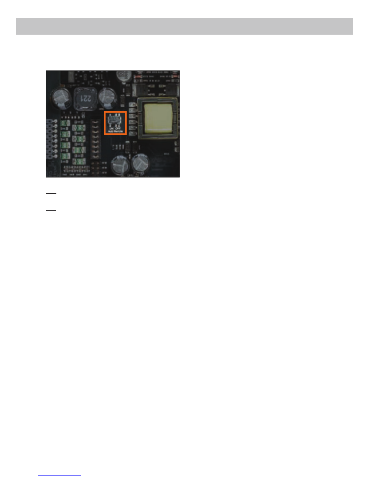
22
by the jumper for adjusting the input sensitivity
of the highlevel inputs (see marking in the fol-
lowing picture).
On: Activation via highlevel speaker input is
enabled (ex works).
Off: Activation via highlevel speaker input is
disabled.
&RQ¿JXUDWLRQRIWKH'63
The general DSP settings should be con-
ducted with the DSP PC-Tool software be-
IRUHXVLQJWKHVLJQDOSURFHVVRUIRUWKH¿UVW
time.
Ignoring this advice may result in damaging the
FRQQHFWHGDPSOL¿HUVWKHORXGVSHDNHUV,QIRU
-
mation about connecting the DSP PRO MK2 to
a computer can be found on page 24.
9. Connecting the remote output
This output (Remote out) is used to supply re-
PRWHVLJQDOVWRWKHH[WHUQDODPSOL¿HUV$OZD\V
use this remote output signal to turn on the am-
SOL¿HUVLQRUGHUWRDYRLGRQRIIVZLWFKLQJQRLVHV
Installation

23
Installation with “Easy Plug Cable”
To simplify installation to an OEM or aftermarket
radio the HELIX DSP PRO MK2 can also be con-
nected using the optional Easy Plug Cable (EPC 5)
which will supply the signal processor with both
power and loudspeaker
signals of the radio. No
factory wires or plugs need to be cut by using this
connection method. The Easy Plug Cable uses the
highlevel inputs A - D.
Connection to an OEM radio is detailed below:
1.
Once the radio has been removed by using the
right tools disconnect the OEM harness from
the radio. Connect the vehicle cable jack con-
nectors of the Easy Plug Cable. You may need
a special ISO-adaptor depending on vehicle
type. In order to verify please check the adaptor
database on the Audiotec Fischer homepage
ZZZDXGLRWHF¿VFKHUFRP
.
2.
Connect the cable plugs to the car radio.
3.
Connect the highlevel plug (8-pole connector)
and the power supply plug (4-pole connector) of
the Easy Plug Cable to the appropriate HELIX
DSP PRO MK2 inputs (
Highlevel Input
A to D
and
Power Input
).
4.
Please note when connecting the power sup-
ply the permanent and switched 12 Volts wires
may be reversed depending on vehicle type.
The HELIX DSP
PRO
MK2 should not be
plugged into the power supply via the ignition
cable as this may cause interferences. Before
connecting the Easy Plug Cable to the HELIX
'633520. YHUL¿FDWLRQ RI WKH SHUPDQHQW
12 Volts wire must be made between the blue
and red wires coming from the ISO connectors
of the harness with a voltmeter. The permanent
12 Volts wire will show voltage even with the ve-
hicle ignition turned off. Once the correct wire is
LGHQWL¿HGFRQQHFWWKHUHGZLUHZLWKMDFNWRWKH
corresponding blue or red wire with plug. The
positive cable of the harness usually has a fuse
of max. 20 A.
Attention:
The ex factory condition is that the
red wires are connected. If you’re uncertain of
assignment ask your dealer.
Note - Cars equipped with MOST bus:
In cars equipped with MOST bus structure it is
PDQGDWRU\WRXQSOXJWKH¿EHURSWLFFDEOHIURPWKH
original radio connector and insert it into the ISO
adaptor which has a dedicated recess for this.
24
,W LV SRVVLEOH WR IUHHO\ FRQ¿JXUH WKH +(/,;
DSP PRO MK2 with our DSP PC-Tool software.
The user interface is designed for easy handling of
all functions and allows an individual adjustment of
each of the ten DSP channels. Prior to connecting
the signal processor to your PC visit our website
and download the latest version of the DSP PC-Tool
software.
Check from time to time for software updates. You
ZLOO¿QGWKHVRIWZDUHDQGWKHUHVSHFWLYHXVHUPDQX
-
al on
ZZZDXGLRWHF¿VFKHUFRP
.
We strongly recommend to carefully read the user
manual (Sound Tuning Magazine) before using the
VRIWZDUHIRUWKH¿UVWWLPHLQRUGHUWRDYRLGDQ\FRP
-
plications and failures.
Important:
Make sure that the signal processor is
not connected to your computer before the software
and USB driver are installed!
In the following the most important steps how to
FRQQHFWDQGWKH¿UVWVWDUWXSDUHGHVFULEHG
1.
Download the latest version of the DSP
PC-Tool software (available on our website
ZZZDXGLRWHF¿VFKHUFRP
) and install it on
your computer.
2.
Connect the signal processor to your computer
using the USB cable that is included in delivery.
If you have to bridge longer distances please
use an active USB extension cable with inte-
grated repeater and no passive extension.
3.
Turn on the signal processor and start the soft-
ware after the Status LED lights up green. The
operating software will be updated automatical-
ly to the latest version if it is not up-to-date.
4.
1RZ \RX DUH DEOH WR FRQ¿JXUH \RXU +(/,;
DSP PRO MK2 with our intuitive DSP PC-Tool
software. Nevertheless, interesting and useful
hints can be found e.g. in our “Sound Tuning
Magazine”, which can be downloaded for free
from our website.
Caution:
We highly recommend to set the vol-
ume of your car radio to minimum position during
¿UVW VWDUWXS $GGLWLRQDOO\ QR GHYLFHV VKRXOG EH
connected to the signal processor until general set-
tings in the DSP PC-Tool software have been made.
Especially if the DSP PRO MK2 will be used in fully
active applications, a wrong setup can destroy your
speakers right away.
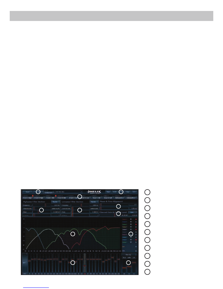
Connection to a PC
1
Load and save
2
Main menu
3
Channel configuration
4
Highpass filter
5
Lowpass filter
6
Time alignment
7
Output level
8
Frequency graph
9
Range of frequency graphs
10
Equalizer
11
EQ fine adjustment
8
1
6
3
4
7
5
2
9
10
11
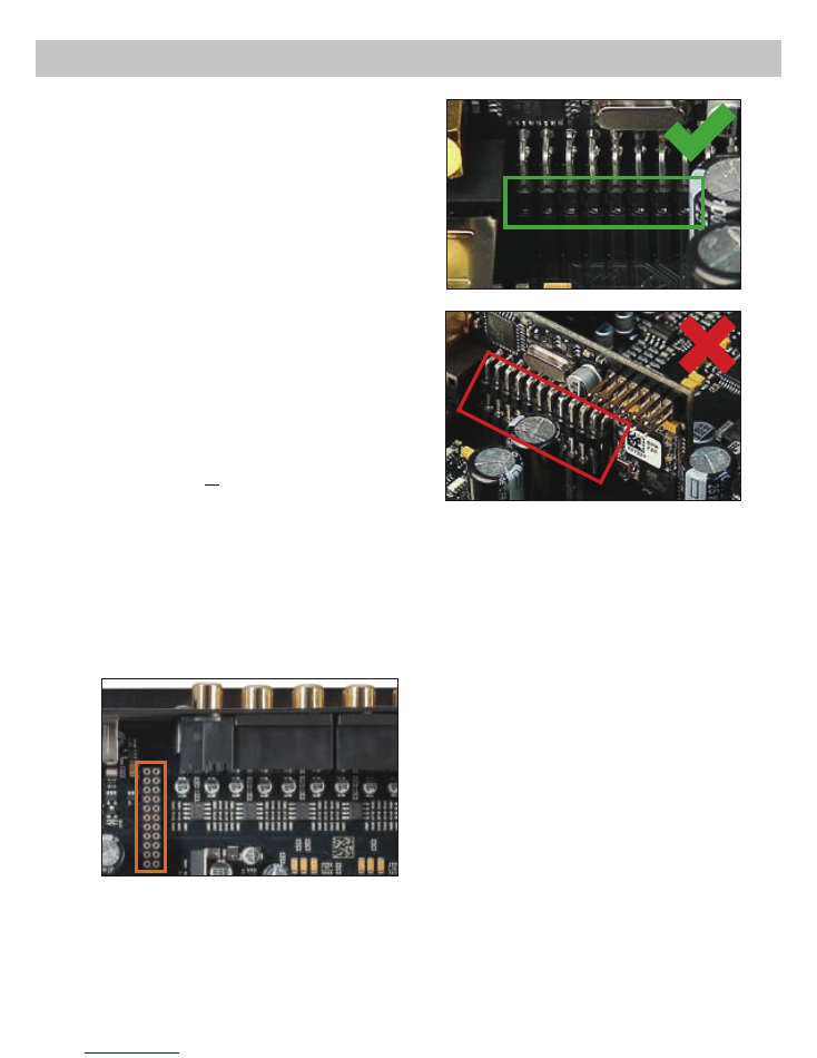
25
HELIX Extension Card slot (HEC slot)
It is possible to extend the functionality of the HELIX
DSP PRO MK2 by inserting an optional
HELIX
Extension Card (HEC) - for example a
Bluetooth
®
Audio Streaming module, an additional optical digi-
tal input, an AUX input or an USB audio input.
To install a HELIX Extension Card it is necessary to
remove the side panel of the DSP PRO MK2 and
replace it by the new side panel that comes with the
HEC module.
Attention: Install the HEC module only in the
GHVLJQDWHG GHYLFH DQG LWV VSHFL¿F VORW 8VLQJ
the HEC module in other devices or slots can
result in damage of the HEC module, the signal
processor, the head unit / car radio or other con-
nected devices!
Read in the following the steps how to install a HEC
module:
1.
First disconnect all cables from the device.
2.
Dismantle the side panel where the USB input
LVORFDWHGE\UHPRYLQJWKH¿YH3KLOOLSVVFUHZV
3.
Pull out the bottom plate sideways.
4.
Prepare the module for installing it into the de-
vice. Any further mounting information will be
found in the instruction manual of the respective
HEC module.
5.
,QVHUW WKH +(& PRGXOH LQWR WKH VSHFL¿F VORW
of the device which is marked in the following
picture.
6.
Make sure that the HEC module is installed
properly and all pins are fully inserted into the
socket.
7.
5HLQVHUWWKHERWWRPSODWHDQG¿[WKHQHZVLGH
panel which is delivered with the HEC module
ZLWKWKH¿YH3KLOOLSVVFUHZV
8.
Bolt the HEC module to the side panel. Precise
mounting information will be found in the in-
struction manual of the respective HEC module.
9.
Reconnect all cables to the device.
10.
Turn on the signal processor. The HEC module
is automatically detected by the device and the
Status LED of the HEC module lights up green.
11.
1RZ\RXDUHDEOHWRFRQ¿JXUHWKH+(&PRGXOH
in the DSP PC-Tool software.

26
96 kHz sampling rate
The HELIX DSP PRO MK2 allows to handle all
signals with the doubled sampling rate of 96 kHz.
Thus the audio bandwidth is no long er limited to
usual values like 22 kHz but allows an extended
frequency response to more than 40 kHz. Doubling
WKHVDPSOLQJUDWHUHTXLUHVVLJQL¿FDQWO\KLJKHU'63
power as the number of possible arithmetic opera-
tions is halved. Only the implementation of the lat-
est DSP chip generation allows raising the sampling
rate to 96 kHz and adding new features plus addi-
tional channels at the same time.
Signal converters with a native resolution of
32 Bit
The HELIX DSP PRO MK2 uses high-class AD and
DA converters of the latest generation with a native
resolution of 32 Bit instead of the common 24 Bit.
The result is an unprecedented precision in signal
conversion that especially optimizes the sound
quality at lower signal levels.
Smart highlevel input
The latest generation of OE car radios incorporates
sophisticated possibilities of diagnosing the con-
nected speakers. If a common signal processor will
EHKRRNHGXSIDLOXUHPHVVDJHVDQGORVVRIVSHFL¿F
features (e.g. fader function) quite often appears -
but not with the DSP PRO MK2.
The new ADEP circuit (Advanced Diagnostics Error
Protection) avoids all these problems without load-
ing the speaker outputs of the OE radio during high
volumes unnecessarily.
Start-Stop capability
The switched power supply of the HELIX
DSP PRO MK2 assures a constant internal supply
voltage even if the battery’s voltage drops to 6 Volts
during engine crank.
Power Save Mode
The Power Save Mode is incorporated in the basic
VHWXS ,W DOORZV WR VLJQL¿FDQWO\ UHGXFH WKH SRZHU
FRQVXPSWLRQ RI WKH DPSOL¿HUV WKDW DUH FRQQHFWHG
to the HELIX DSP PRO MK2 once there’s no input
signal present for more than 60 seconds. Please
note that in many up-to-date cars with “CAN” or any
other internal bus structures it may happen that the
radio remains “invisibly” turned on for up to 45 min.
even after locking and leaving the car! Once the
“Power Save Mode“ is active the remote output and
WKHUHIRUH WKH FRQQHFWHG DPSOL¿HUV ZLOO EH WXUQHG
off. The HELIX DSP PRO MK2 will reactivate the
remote output within a second if a music signal is
applied. It is possible to either modify the turn-off
time of 60 sec. or completely deactivate the “Power
Save Mode” via the DSP PC-Tool software.
Automatic Digital Signal Detection
Switching from analog input to one of the digital in-
puts is done automatically as soon as a signal is
detected on the
Optical Input
or
Coax Input
. This
feature can be deactivated in the DSP PC-Tool soft-
ware. Alternatively you can use an optional remote
control for manual switching between analog and
digital inputs.
Unique Features of the HELIX DSP PRO MK2

27
Inputs ...............................................................................8 x RCA / Cinch
8 x Highlevel speaker input
1 x Optical SPDIF (12 - 96 kHz)
1 x Coax SPDIF (12 - 192 kHz)
1 x Remote In
Input sensitivity ................................................................RCA / Cinch 2 - 4 Volts
Highlevel 5 - 10 or 10 - 20 Volts
Outputs ............................................................................10 x RCA / Cinch
1 x Remote Out
Output voltage .................................................................8 Volts
Frequency response ........................................................10 Hz - 44,000 Hz
DSP resolution .................................................................64 Bit
DSP power ......................................................................295 MHz (1.2 billion MAC operations/second)
Sampling rate ..................................................................96 kHz
DSP type .........................................................................Audio signal processor
Signal converters .............................................................A/D: Asahi Kasei 32 Bit
D/A: Asahi Kasei 32 Bit
Signal-to-noise ratio digital input .....................................116 dB (A-weighted)
Signal-to-noise ratio analog input ....................................110 dB (A-weighted)
Total harmonic distortion (THD+N) digital input ...............< 0.0005 %
Total harmonic distortion (THD+N) analog input .............< 0.001 %
IM distortion (IMD) digital input ........................................< 0.002 %
IM distortion (IMD) analog input ......................................< 0.004 %
Crosstalk..........................................................................> 90 dB
Operating voltage ............................................................9.6 - 18 Volts (max. 5 sec. down to 6 Volts)
Current draw ....................................................................510 mA
Max. remote output current .............................................500 mA
Additional features ...........................................................HEC slot, Ground lift switch, Control Input,
ADEP circuit, Auto Remote switch
Dimensions (H x W x D) ..................................................40 x 177 x 150 mm / 1.58 x 6.97 x 5.91“
Technical Data
Warranty Disclaimer
The limited warranty comply with legal regulations.
Failures or damages caused by overload or im-
proper use are not covered by the warranty. Please
return the defective product only with a valid proof
of purchase and a detailed malfunction description.
7HFKQLFDOVSHFL¿FDWLRQVDUHVXEMHFWWRFKDQJH
Errors are reserved! For damages on the vehicle
and the device, caused by handling errors of the
device, we can’t assume liability. This product is
WDJJHGZLWKD&(&HUWL¿NDWLRQPDUN7KHUHE\WKHVH
GHYLFHV DUH FHUWL¿HG IRU WKH XVH LQ YHKLFOHV ZLWKLQ
the European Community (EC).
Note:
“The
Bluetooth
®
word mark and logos are registered trademarks owned by Bluetooth SIG, Inc. and any use of such marks by
Audiotec Fischer GmbH is under license. Other trademarks and trade names are those of their respective owners.”

Audiotec Fischer GmbH
Hünegräben 26 · 57392 Schmallenberg · Germany
Tel.: +49 2972 9788 0 · Fax: +49 2972 9788 88
(PDLOKHOL[#DXGLRWHF¿VFKHUFRPā,QWHUQHWZZZDXGLRWHF¿VFKHUFRP