Full Text Searchable PDF User Manual

November 2015 Revision 1
Installation and Operating Instructions for
Greymetal Wood Burning Stoves
Arctic 5
Lumo 5
Lumo 5 Rotary
Orbit
Greymetal Ltd
FTS
Drome Road
Zone 1
Deeside Industrial park
CH5 2LR

- 2 -
Important – please read section 7.2 before lighting!
Contents
1
INTRODUCTION ............................................................................................................................. 3
2
COMBUSTION AND HEATING FUNCTION ...................................................................................... 3
3
DESIGN .......................................................................................................................................... 3
4
SAFETY REQUIREMENTS ................................................................................................................ 4
4.1
General provisions ........................................................................................................................ 4
4.2
Safe distance of the stove in the room from flammable substances ............................................ 4
4.3
Danger Warnings .......................................................................................................................... 4
4.4
Fire in the chimney ....................................................................................................................... 5
5
ASSEMBLY ..................................................................................................................................... 5
5.1
Instructions for stove assembly .................................................................................................... 5
5.2
Central Air Feed (CAF) ................................................................................................................... 6
6
FUEL .............................................................................................................................................. 6
7
OPERATION ................................................................................................................................... 6
7.1
Combustion process ..................................................................................................................... 6
7.2
First kindling .................................................................................................................................. 7
7.3
Kindling ......................................................................................................................................... 7
7.4
Heating .......................................................................................................................................... 7
7.5
Glass cleaning / ‘Air-Wash’ function ............................................................................................. 8
7.6
Removal of ash.............................................................................................................................. 8
7.7
Operation with the door open ...................................................................................................... 8
7.8
Dampers left open ........................................................................................................................ 8
8
CLEANING AND MAINTENANCE .................................................................................................... 8
9
MOST FREQUENT FAILURES .......................................................................................................... 9
10
UNCOMMON FAILURES ................................................................................................................ 9
11
SERVICE ......................................................................................................................................... 9
11.1 Guarantee and after-guarantee service ........................................................................................ 9
11.2 Ordering of spare parts ................................................................................................................. 9
12
STOVE PACKAGE AND DISPOSAL ................................................................................................... 9
12.1 Package ......................................................................................................................................... 9
12.2 Stove disposal ............................................................................................................................... 9
13
ANNEXES ..................................................................................................................................... 10
13.2 Distances to combustible materials and size of hearth .............................................................. 10
13.3 Changin flue exit / uptake ........................................................................................................... 10
13.4 Instructions for cleaning cast-iron and tile stoves ...................................................................... 11

- 3 -
1
Introduction
The appliance is designed to heat domestic residential and social spaces. The stove is intended for use only by
adults with occasional attendance and supervision. The room in which the stove is installed must be provided with
a sufficient fresh air supply, possibly by gaps through windows and doors. In well-sealed buildings, sufficient fresh
air supply to the room must be ensured by a vent of 550mm
2
for each Kilowatt of rated nominal output.
The local Building Control department must be consulted prior to any DIY installation.
Please follow all of the instructions when installing and operating the stove.
The Clean Air Act 1993, Smoke Control Areas and DEFRA
Under the Clean Air Act, local authorities may declare the whole or part of the district of the authority to be a
smoke control area. It is an offence to emit smoke from a chimney of a building, from a furnace or from any fixed
boiler if located in a designated smoke control area. It is also an offence to acquire an "unauthorised fuel" for use
within a smoke control area unless it is used in an "exempt" appliance ("exempted" from the regulations which
generally apply in the smoke control area).
The Secretary of State for Environment, Food and Rural Affairs has powers under the Act to authorise smokeless
fuels or exempt appliances for use in smoke control areas in England. In Scotland and Wales this power rests with
Ministers in the devolved administrations for those countries. Separate legislation, the Clean Air (Northern Ireland)
Order 1981, applies in Northern Ireland. Therefore, it is a requirement that fuels burnt or obtained for use in
smoke control areas have been "authorised" in Regulations, and that appliances used to burn solid fuel in those
areas (other than "authorised" fuels) have been exempted by an Order made and signed by the Secretary of State
or Minister in the devolved administrations.
Further
information
on
the
requirements
of
the
Clean
Air
Act
can
be
found
here:
http://smokecontrol.defra.gov.uk/
Your local authority is responsible for implementing the Clean Air Act 1993 including designation and supervision
of smoke control areas and you can contact them for details of Clean Air Act requirements.
The Arctic 5, Lumo 5, Lumo 5 rotary, and Orbit 5kW stoves are exempt appliances that have been recommended as
suitable for use in smoke control areas when burning wood logs; and have been factory fitted with a secondary air
control which cannot be fully closed.
2
COMBUSTION AND HEATING FUNCTION
The stove is designed for combustion of wood and wood ‘eco’ briquettes by a burn-through system that ensures
excellent combustion conditions. If not in a smoke control area, lignite briquettes may also be used.
The heating function is achieved mainly by convection, and partially by radiant heat. The convection system is able
to heat up particularly cold rooms relatively quickly.
Convection heating works by sucking in the air from the room through the vents at the bottom of the stove into
the space between the firebox and the outer casing. It is heated in-between the double walls of the stove causing
it to rise. It flows back into the room through the vents in the upper part of the stove.
Heat is also radiated by the surface of the stove body, but the main source of radiant heat is the glass door surface.
- 4 -
3
DESIGN
The appliance is fabricated from pressed and welded sheet steel, and may include as an optional extra a stone or
ceramic outer casing. The stove combustion chamber is lined with refractory (heat resistant) vermiculite firebricks.
The refuelling door of the stove has a
ceramic
window, resistant to very high temperatures and thermal shocks.
The ceramic is almost clear, allowing heat radiation from the combustion chamber (‘firebox’) to pass through; and
allows a view of the flames when burning. There is a sold cast iron grate at the bottom of the firebox and an ash pit
below. The stove is spray painted with silicone polymer paint, resistant to high temperatures.
Primary air, secondary air and tertiary air is supplied to the firebox. Primary air is used for lighting and is
channelled under the grate; secondary air is channelled onto the glass from above and provides the self-cleaning
(‘air-wash’) of the glass. Tertiary air is fed to the upper part of the firebox through the vents at the back of the
firebox, and provides further combustion of un-burnt gases (burnout).
The Arctic, Lumo (non-rotary) and Orbit stoves have the option of feeding combustion air through the Central Air
Feed (CAF) from the outdoors. If the CAF is used, the stove does not take air from the room. These options are
specified in the
Product Technical Sheet (TS)
.
4
SAFETY REQUIREMENTS
4.1
General provisions
The principles of fire protection in the Building Regulations publication
“
Approved Document J
-
Combustion appliances and Fuel Storage systems (2010 edition incorporating 2010 and 2013 amendments)
http://www.planningportal.gov.uk/uploads/br/BR_PDF_ADJ_2010.pdf
must be observed when operating and
installing the stove.
The appliance may be used in a normally experienced environment according to
Approved Document J
.
In any change of environment, when a temporary danger of fire or explosion could emerge (e.g. when using glues,
solvents, paints etc.), the stove must not under any circumstances be in operation. The stove may be used further
only after thorough ventilation of the room, at best by draught.
The stove must be connected to a chimney with a draught of at least 12 Pascals. The installer should
test and certify the adequacy of the draught. The stove may be connected only to its own independent chimney.
4.2
Safe distance of the appliance from combustible surfaces:
Hearth:
The appliances
do not
cause the
hearth temperature
to exceed 100°C and can be placed on a non-combustible,
non-constructional hearth of 12mm thickness. The hearth must exceed the dimensions of the stove by at least 15
cm on each side, 10 cm at the back and 30 cm to the front. It must have a minimum thickness of 12mm.
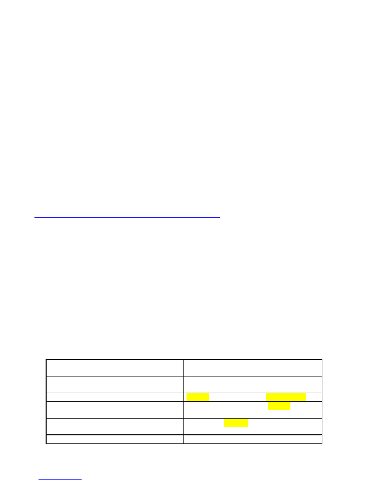
Table No. 1 – Information on flammability degree of some building materials according to BS EN 13501-1+A1
Status of flammability of building materials and
products
Building materials classified in the relevant
flammability degree
A non-flammable
granite, sandstone, heavy porous concretes,
bricks, ceramic tiles, special plasters
B uneasily flammable
acumine, wood-cement board, lihnos, itavere
C1 hardly flammable
broad-leaved wood, plywood, sirkoklit, laminated
paper, formica
C2 medium flammable
chipboards, solodure, cork boards, rubber,
flooring materials
C3 easily flammable
wood-fibre boards, polystyrene, polyurethane
- 5 -
When installing the stove in a room with combustible substances of flammability classes B, C1 and C2, safe
distances from the front of
800 mm
and in other directions
200 mm
must be observed, unless the Technical Sheet
or the CE plate on the rear of the stove specifies otherwise.
If the stove is installed in a room with combustible substances of class C3, the above stated distances must be
doubled.
Please consult
Table No. 1
for clarity.
There is no requirement for minimum clearance to non-combustible surfaces around the sides and back of the
stove. However, 100 mm is recommended to allow for heat and air circulation to the room. The further the stove is
placed in the room, the better the heat distribution.
Refer to Diagram 30, Page 42 of Document J for further installation dimensions and requirements for non-
combustible wall thickness etc.
4.3
Danger Warnings
Flammable liquids MUST NOT be used for lighting or heating! It is further forbidden to burn any plastics, wooden
materials with chemical binders (chipboards etc.) as well as unsorted household waste with remnants of plastics or
chemically treated wood etc.
The stove must be operated by adults only! It is inadmissible to let children near the stove
without supervision of adults. The stove surface is super-heated, particularly the glass; you can
suffer serious burns by touching it.
Where there are children under 8, a fire-guard must be used.
In operation, the stove requires occasional attendance and supervision. A protective mitten is included in each
stove for the safe operation of the air controllers and door handle. DO NOT put any combustible items on the
stove during operation or when it is still warm as they can ignite. DO NOT put any containers of cold liquids onto a
hot stove with stone or ceramic casing as it will cause the stone to break.
Please be extremely cautious when handling the ash pit and when removing hot ashes because there is a danger of
being burnt. Hot ashes must not come into contact with flammable items - e.g. when being emptied into dustbins.
The stove may be operated only according to these Instructions. It is inadmissible to perform any
unauthorized modifications to the stove.
4.4
Chimney Fires
If a fire occurs in the chimney, the fire in the stove must be put out immediately by removing the burning fuel with
the help of a small shovel to a suitable non-flammable container and the fire brigade must be called immediately
by dialling either 112 or 999.
5
ASSEMBLY
Warning:
When assembling the stove, all regulations in particular those related to national and European
standards for this type of appliance must be observed, refer to Approved Document J.
5.1
Instructions for stove assembly
Place the combustion air vents, if needed, so that they cannot become blocked.

- 6 -
When installing the appliance, adequate access for cleaning of the stove, firebox, connecting pipes and
chimney must be provided.
The appliance must be installed on a floor with adequate load bearing capacity.
If the stove hasn’t been used for some time, check the flue-ways to see whether or not they have
become blocked.
If installing a glass hearth, adhesive cork discs are placed underneath in order to eliminate unevenness.
Seal the glass with transparent silicon to the floor around the edges, so that dirt can’t go under it.
The flue pipes can be connected to most models to the top or rear exit (see Technical Sheet). The choice
of which exit depends on the user or on the flue draught. When changing the flue exit, see the instructions in
Annex No. 12.3
.
The cover for the hole in the stove’s outer shell can be found in the ash pan. When assembling and
disassembling the firebox plug and the cast-iron spigot, make sure they are air-tight using fire rope.
In stoves having a metal sheet top plate fitted with a break-off cover, the plug can be broken off with
the help of a screwdriver.
When using the rear outlet on stoves with a stone top plate, a lid made of the corresponding stone type
is included to plug the hole in the upper stone.
5.1.2. Chimneys and Flue Pipes:
Approved Document J deals with the installation of chimneys and flue pipes and should be referred to at all
times.
1.
There is a minimum gap required between an un-insulated flue pipe and combustible material. To a
combustible material it must be at least 3 x the outside diameter of the flue pipe (450 mm for 6” single wall
flue pipe). To a proprietary non-combustible shield it must be at least 1.5 x the flue diameter (e.g. 225 mm
for 6” single wall flue pipe).
2.
The rear flue exit is normally used when the chimney is tall and provides too powerful an up-draught.
Where the chimney is short, and the draught weak, the top flue exit will give better performance.
3.
Flue connections should be sealed with a suitable proprietary sealant such as fire cement or high
temperature rope seal. Cartridge sealing compounds are superior to fire cement.
4.
If a suitable approved factory made chimney system is to be used, it should be installed according to the
manufacturer’s instructions and the regulations found in Approved Document J. (“Stainless Steel Twin Wall
Insulated Chimney System”.)
5.
The flue draught should be at least 12 Pa for optimal performance, but in most cases a flue height of
4.5m should be adequate, measured from the stove’s top air inlet to the top of the flue.
6.
No horizontal sections are allowable.
7.
Flues should have a maximum of 4 bends with angles of 45 degrees. And a maximum of two bends in-
between each sweeping access point. [A D J Page 27 Diagram 15].
8.
The flue exit from the building should be positioned to comply with the requirements of the Building
Regulations. These can be seen on A D J page 31 Diagram 17.
9.
If the chimney is too high (draught exceeds 35 Pa) or so that the chimney draught can be regulated on
days with strong winds, it is necessary to fit the flue with a damper or flue balancer.
10. No other heating appliances should be connected to the same Flue or Chimney system.
5.2
Central Air Feed (CAF)
Sufficient fresh combustion air must be ensured by a hole with a minimum 10 cm diameter or equivalent area.
The hole for fresh air can be substituted by leaky windows and doors but we always advise an independent fresh
air supply.
If the option of a direct fresh air supply through the Central Air Feed from the outdoors to the stove is used, it
must be fed through a pipe with a diameter of 100 mm or equivalent ducting. The length of the pipe must not
exceed 5 metres; the length is reduced by 1 m for each 90 degree bend. The connector of the Central Air Feed is
bought as an optional extra. The Central Air Feed must never be blocked.

- 7 -
WARNING:
Kitchen and other Extractor fans: If they are placed in the same space (or house) as the
stove, then they must have their own independent air vent. It must be able to supply the same volume
of air to the space that the fan is capable of extracting. The Central Air Feed must also be used.
6
FUEL
The wood stove is designed for heating with firewood, wood briquettes also referred to as ‘heat logs’, and for
some products when not in smoke control areas, lignite briquettes (see TECHNICAL SHEET). The humidity of the
wood should be under 18%. Wood stored for at least 3 years in a well aired shed achieves such humidity. Kiln-dried
wood is the preferred fuel. When heating with briquettes, they must be stored in a completely dry environment;
otherwise they will become damp and fall apart. When heating with “wet” wood, the stove loses at least 20% of its
efficiency and output. The fuel consumption rises and the stove will “tar”. The tar will stain the glass heavily,
making cleaning difficult.
IMORTANT:
Only the above stated fuels may be used for heating in the stove. Liquid fuels and coal must not be used
undefined household waste including plastics etc. must not be burnt.
Refuelling on to a low fire-bed:
If there is insufficient burning material in the fire-bed to light a fresh fuel loading, excessive smoke
emission will occur. Refuelling must be carried out onto a sufficient quantity of glowing embers and ash
so that the new fuel load will ignite in a reasonably short period. If there are too few embers in the fire
bed, add suitable kindling to prevent excessive smoke.
Fuel overloading:
The maximum amount of fuel specified in this manual should not be exceeded, overloading can cause
excess smoke.
The optimal amount of wood to achieve the nominal output is found in the Technical Sheet of the
stove.)
7
OPERATION
The fireplace stove may be operated only in compliance with these Instructions. The stove must not be operated
by children. Only the defined fuels may be used for heating. The stove requires occasional supervision. The
manufacturer supplies a protective mitten together with the stove for safe operation.
7.1
Combustion process
The combustion of wood, eco briquettes and in some stoves lignite briquettes is carried out by the burn-through
system, which means that the combustion takes place in the whole fuel load at the same time.
To ensure the optimum conditions for easy kindling and successful ignition, a sufficient quantity of air must be fed
under the burning fuel, through the grate. That air is called the
primary air
and is always controllable. The feed of
secondary air
is also independently controllable. It improves the combustion and improves the cleaning of the
door glass. The tertiary air is a smaller supply and is intended to improve the general combustion process and is
permanently open.
When the right quantity and proportion of the types of air fed to the right places of the combustion chamber are
achieved, the combustion efficiency is increased, reducing the emissions of harmful gases to the atmosphere. The
arrangement of the air controllers is represented on the diagram in the Technical Sheet supplied with each stove.
In practice, the exact setting of the air control levers varies with a number of factors – the fuel humidity, the fuel
type, the chimney draught, the outside air pressure conditions etc. Therefore the user must fine tune the burning
process for optimal flame intensity and quality.
Generally speaking, however, when lighting, both vents are set fully open and during the main operation of the
stove, the primary is closed and the secondary left open in order to maximise the glass cleaning.

- 8 -
7.2
IMPORTANT! - First firing
The paint can become soft for a short time during first lighting. Do not touch the outer surface and do not put
anything on the stove. The rope seal of the door can also stick to the body of the stove at this time - leave the door
slightly open initially.
The first ever burn in the stove must be carried out so that the temperature rises slowly. It has been shown that in
this way, the paint is hardened more durably.
The manufacturer supplies the stove in a crate made of spruce timber; the wood is very dry and it has been chosen
especially for the first burn.
It is important that during the first burn, the full output is gradually achieved and maintained for an hour.
During
that time, the paint is burnt out, stabilized and achieves full hardness and abrasion resistance.
There will be some smoke and a chemical smell from the paint. The room must be extremely well ventilated and
pets removed.
7.3
Kindling
The grate should be clear before kindling. Place a large amount of crumpled newspaper or solid firelighters and
several pieces of kindling in the firebox. Set the primary air controller (choke) fully open. Set fire to the paper and
close or almost close the door. Leave to burn for several minutes until a high flame is reached and the chimney
fully warmed for maximum draught.
7.4
Heating
7.4.1
Burning wood and wood briquettes
Following the initial kindling, we recommend closing the primary air supply fully or almost fully. The burning rate is
regulated by the secondary air controller.
7.4.2
Burning lignite briquettes
The burning rate is regulated by the primary air control. Following the initial lighting phase, the manufacturer
recommends closing the secondary air supply fully or almost fully.
In practise, the optimal position of the controls will be a matter of trial and error and will vary depending on the
chimney draught.
Feed with fresh fuel when there are only glowing embers in the firebox
.
When the wood has burned down to embers, open the stove door 10 to 15 mm and wait 15 to 20 seconds before
opening the door fully and quickly put the fuel into the firebox. This procedure will significantly decrease the
volume of smoke entering the living room. To further reduce smoke spill-out, open the starting flap (on some
models only, labelled [firing valve]) immediately prior to loading.
7.5
Glass cleaning / ‘Air-Wash’ Function
This is dependent on the use of the correct dry fuel, plenty of combustion air (particularly secondary air) and
sufficient chimney draught. The method of operating the stove also influences the cleanness of the glass. We
advise you to stoke up only one layer of fuel, distributing the fuel as uniformly as possible in the firebox and as far
as possible from the glass. The same applies to briquettes. The distance between logs should be 5 to 10 mm. If the
glass darkens during burning, increasing the burning intensity will usually clean the glass automatically.

- 9 -
7.6
Removal of ash
Depending on the length and intensity of the heating phase, the ash should be shaken through the grate to the ash
pan with the help of a poker.
Please ensure that the ash pan is not overfilled, thereby obstructing the air feed
through the grate and leading to subsequent problems with lighting or burning.
The ash pan must be emptied when the ash is cold, ideally when preparing the lighting/kindling stage.
Ash from
burnt wood can be used in compost or as a fertilizer.
Warning:
Before emptying the ash pit, make sure it doesn’t contain hot embers that could start a fire.
7.7
The appliance must not be operated with the appliance door open
except briefly
when fuelling
.
Operation with the door open can cause excess smoke to enter the room.
7.8
Air Controls left open
Running for any length of time with the air controls fully open can cause excessive smoke. The appliance must not
be operated with air controls, appliance dampers or door left open except as directed in the instructions.
8
CLEANING AND MAINTENANCE
The appliance must be cleaned at least once a year; it must always be cold before cleaning.
During cleaning, any accumulations of tar in the flues, in the firebox and on the baffle plates above the
firebox should be removed as much as possible.
The grate must be kept unobstructed.
Repair any parts of firebrick lining that have fallen out, ideally with a new firebrick. The integrity of the
lining should be monitored during the heating season. The gaps between the individual boards serve for
thermal expansion, preventing cracking; the gaps
must not
be filled in any way (e.g. with accumulated ash).
Some cracks in vermiculite firebricks are normal and are to be expected. They
remain functional and should remain in use unless they have appreciable holes, have
disintegrated or fallen out.
Stove glass cleaners of varying strength are available, but damp newspaper can also work. The glass
must be cleaned only when cold. Never use water to clean painted parts of the stove surface; soft foam
sponge or soft flannel cloth will be suitable.
By regular cleaning of the chimney you will prevent soot deposits on the chimney walls from igniting.
We advise to use only dry, no more than slightly moistened cloth to clean the ceramic tiles. Clean the
stove only when cold.
The textured stucco surfaces should be cleaned only with the help of a broom or vacuum cleaner.
9
COMMON FAULTS
Disintegrated or broken vermiculite brick
A vermiculite board or complete lining can be ordered as spare part from the distributor.
Door sealing
A new rope seal can be ordered as a spare part from the distributor.
Damaged door, damaged glass.

- 10 -
Changing the door glass is fiddly and requires a modicum of practical ability but is not complicated. Make
sure the screws are cleaned with a fine wire brush and soaked overnight with a solvent such as white
spirit to soften the tar before attempting to remove them. Do not get solvent on the paint. Do not over-
tighten screws when replacing.
Doors virtually never need replacing, but changing the door is not difficult for anyone with a small degree
of practical skill. Contact the distributor for specific advice before attempting to remove the door.
10
UNCOMMON FAULTS
Some microscopic cracks may occur, sometimes referred to as “hair cracks”, during the traditional method of
manufacturing the ceramic tiles for the stoves’ outer casing. Such hair cracks are natural and are
not
considered
defects.
11
SERVICE
11.1
Guarantee and after-guarantee service
The guarantee and after-guarantee service is provided by the principal manufacturer, ABX, through its distributor
in the UK, Greymetal Ltd:
Greymetal Ltd
/
FTS
Drome Road
Zone 1, Deeside Industrial Park
CH5 2LR
Tel 01244 913320
e-mail:
info@greymetal.co.uk
Technical information related to installation and operation and spare parts may be obtained from
technical@greymetal.co.uk
11.2
Ordering spare parts
When ordering spare parts, please state the:
stove type
year of production/purchase
serial number
Identify the spare part with the help of the Technical Sheet, stating the name of the part and possibly its number
or position according to the diagram. Send the order by e-mail. Spare parts and accessories can be ordered from
the seller or directly from the manufacturer.
12
STOVE PACKAGE AND DISPOSAL
12.1
Package
The fireplace stove is, unless stated otherwise (see TECHNICAL SHEET), delivered in assembled condition on a
wooden transport pallet in protective wooden casing. The stove is wrapped in shrink wrap and fixed to the pallet.
The following package disposal is possible from the perspective of wastes:
Disassemble and burn the wooden base (see First kindling).
Throw the bag to municipal waste or deliver it to a collection point.
Cardboard: recyclable.
12.2
Stove disposal
For disposal of the entire stove, throw the vermiculite lining, glass and seals to land fill waste. Also ceramic, stone
and tile can be put into the rubble skip at the recycling centre. The steel sheet body and the together with cast iron
parts can be taken to a scrap yard.
- 11 -
13
ANNEXES
1.
Technical Sheet of the relevant stove type (separate sheet)
2.
Distances and size of hearth
3.
Swapping the flue spigot
4.
Instructions for cleaning of cast-iron and tile ovens
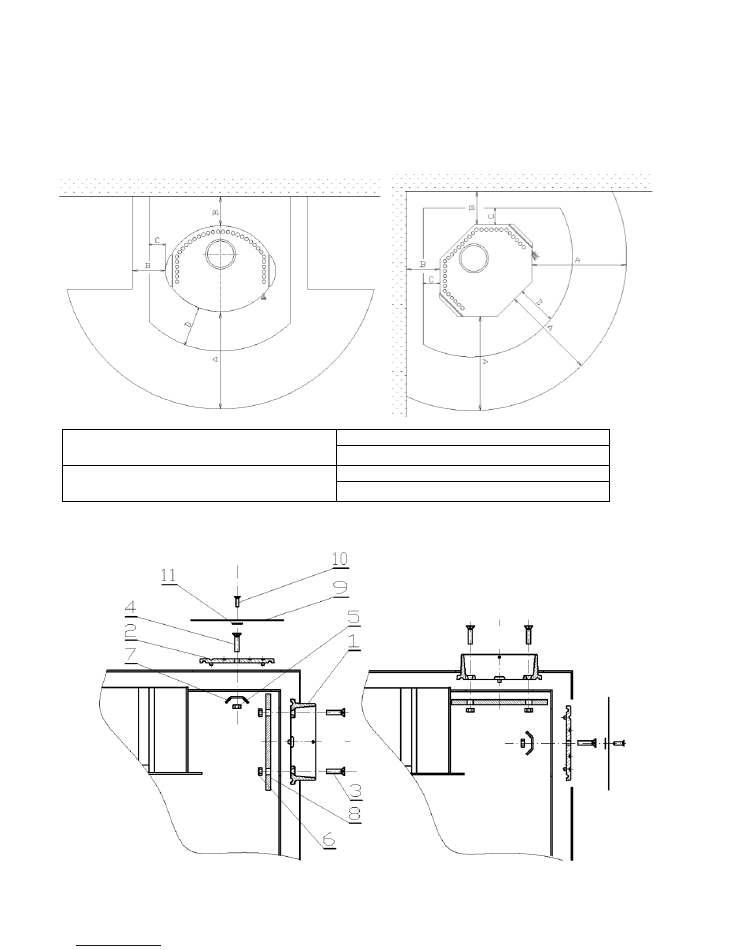
13.2
Distances and size of hearth
13.3
Swapping the flue spigot
Minimum distances from flammable
materials
A ≥ 800 mm
B ≥ 200 mm
Minimum size of protective foundation
board
C ≥ 100 mm
D ≥ 300 mm
REAR OUTLET
TOP OUTLET
- 12 -
1. UPTAKE NECK
∅
150
7. COVER PARTITION
2. UPTAKE PLUG
8. UPTAKE PARTITION
3. SCREW OF UPTAKE NECK M6 2 PCS
9. STEEL SHEET OF UPTAKE COVER
4. SCREW OF PLUG M8
10. SCREW OF UPTAKE COVER
5. NUT M8
11. HANDLE OF UPTAKE COVER
6. NUT M6 2 PCS
NOTE: FOR STOVES WITH A WELDED STEEL UPTAKE, THE UPTAKE PLUG (2) IS TO BE MOVED FROM ONE UPTAKE TO
THE OTHER USING ITEMS 4, 5, 7.
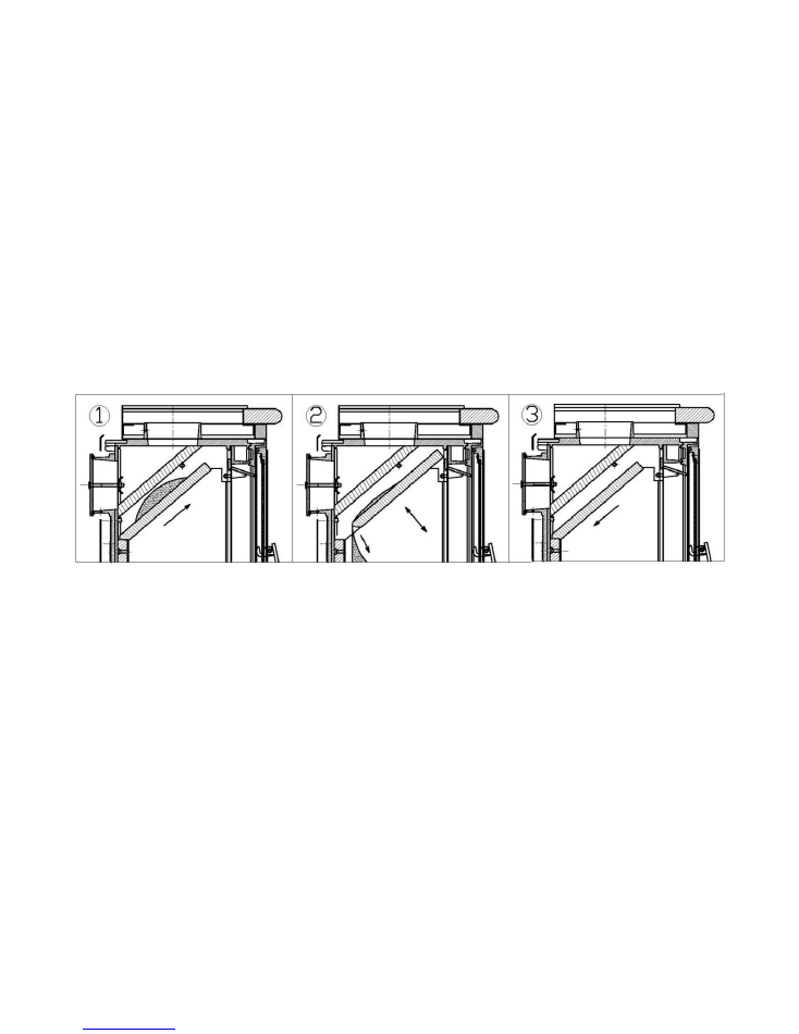
13.4
Instructions for cleaning of cast-iron and tile stoves
After long-term use of cast-iron and tile stoves and/or if some unsuitable fuel is used, the space between
vermiculite baffle plates and the fire box may become clogged with soot. The stove suffers insufficient draught and
does not heat properly. Therefore this space should be cleaned on a regular basis, i. e. at least once every 6
months. For the cleaning procedure, see the scheme.
(1)
The lower vermiculite guiding plate is pushed upwards.
(2)
The soot is released by careful knocking so that it falls down into the firebox.
(3)
The lower vermiculite plate is put back to its original position.

- 13 -