Full Text Searchable PDF User Manual

Version 3.04 - 0208
GB
User Manual
Combi 185 L - LS - S
Optima 310
-Heat Pump and Domestic Hot Water

2
Optima 310
Table of contents
Page
1.
Users Guide
1.1 Use ............................................................................
3
1.2
Altering of the operation data ....................................
3
1.3 Operating menu
........................................................
4
1.4 Week program ..........................................................
9
1.5 Defrost program ........................................................
9
1.5 Special functions .....................................................
10
1.7 Factory default scheme ...........................................
10
2.
Function
2.1 Controller Optima 310..............................................
11
2.2 Extra capacity .........................................................
11
2.3 Operation safety
......................................................
11
2.4 Warnings .................................................................
11
3.
Maintaining
3.1 Connecting to computer ..........................................
12
3.2 Servicing
.................................................................
12
3.3 Water circuit and tank
.............................................
12
3.4 Demounting
.............................................................
13
4. Fault finding
4.1 High pressure switch ...............................................
14
4.2 Safety breaker for el heater ....................................
14
4.3 Heat pump will not run ............................................1
4
4.4 Air error ...................................................................
14
Subject to Technical Modifications
3
Optima 310
1. Users guide
Optima 310 AC/EC
All Genvex combined domestic ventilation- and water
heat pumps and domestic hot water of the types Combi
185, 185S, 185L and 185LS are supplied with optima
310 controller with a factory setup, which enables the
immediate start of the unit without changing the operating
settings. The factory setups are only basic settings that
can be changed according to the operational wishes and
demands, you have for your home, to obtain an optimal
operation and use of the equipment.
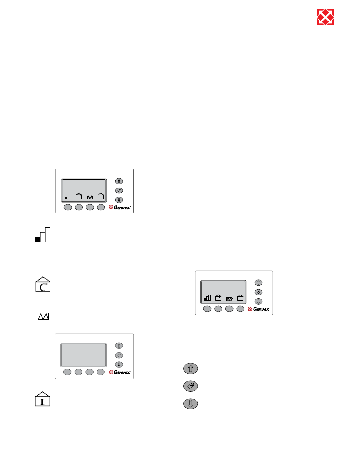
1.1 Use
Use this button to change fan speed between
low, medium and high. (Level 1, Level 2, Level 3).
To stop the unit press this button 3 - 4 seconds
until all levels are switched off. Heating coils
will turn off immediately while the fans will run
for app. 2 minutes in order to cool down the re-
heating surfaces.
Use this button to change the desired room
temperature.
Using this button, allows a signal to be sent to
switch on the electric element to heat up the
domestic hot water if required.
Use this button to view all temperatures in the
unit, and press arrow down to view which relays
are in operation. This will allow you to get a quick
overview of the operation of the unit.
The following temperatures and relay functions are
shown in the info menu. The relays are ON when the
display shows 1:
T1: Supply air
T2: Room
T3: Fresh air
T4: Exhaust air
T5: Before coil (cooling coil)
T6: Coil (cooling)
T7: D. water top
T8: D. water bottom
T9: Solar collector
R1: Compressor
R3: Air heating
R2: El-heater
R8: Solar pump
R7: Supply cool
R6: Heat room
R5: Dom. water
R4: Defrost
1.2 Altering of the operation data
Optima 310 comes with a factory setup, which enables an
immediate start of the unit. The factory setup is basic and
must be adjusted to the operational requirements and
demands of the individual home, in order to obtain the
optimum operating benefit from the unit.
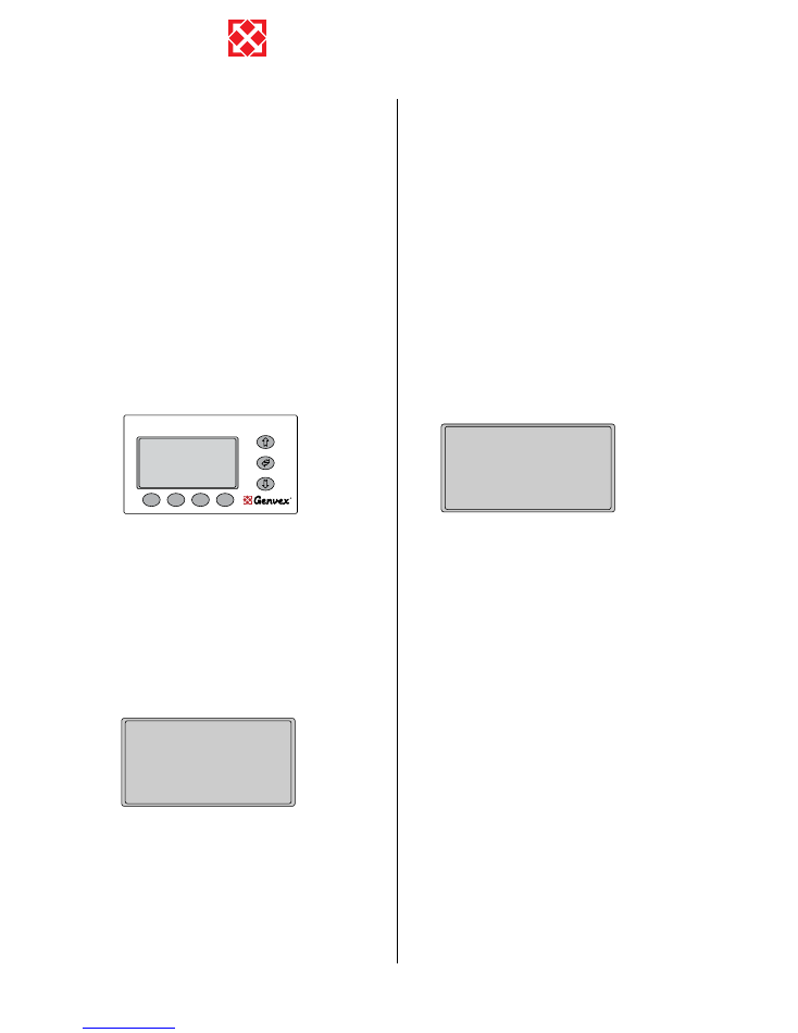
The display normally shows the main menu, at which
“day of the week, time, room temperature and short-cut
keys” can be seen.
Press “Arrow up, Arrow down, Enter” to enter the
operating menu. The display now shows the first four
points on the operating menu.
Press “Arrow down” to change from one
menupoint to the next. Press “Arrow up” to change
from one menupoint to the previous one.
If you wish to flick through the pages of the
‘operation menu’ you may press the “Enter”-button
in the middle and this will change the whole page
to the next set of menupoints.
When “>>” appears opposite a text, shown as example
”language” in below display, you see, there is a “0” on the
“Set point” line. By pressing “>”, the set point changes to
“1”.
ON/OFF
C
I
ON/OFF
Room temperature
21.5
o
C
Wednesday
12:18
Supply
� �
�
48.0
Room
�
�
�
26.8
Fresh air
��
�
22.5
Exhaust air
�
�
0
6.0
Before coil
�
�
23.0
Coil
��
�
�
0
6.7
Info menu
C
I
ON/OFF
Room temperature
21.5
o
C
Wednesday
12:18
4
Optima 310
By pressing “OK”, the control system reverts to the main
menu and the text changes to English. Now all text in
the display appear in English. If, instead, the set
point is adjusted to “2”, all text in the display will
be shown in German.
When the desired language has been selected, enter the
main menu once again and change to the next operating
point by pressing “Arrow down”.
If you wish to flick through the pages of the operating
menu, you may press “Enter” to change the whole page to
the next set of menu points.
If you wish to return to the previous operating point,
you may press “Arrow up”.
If you wish to leave the operating menu, press “Exit”.
The operating menu will automatically shut down and
return to the main menu if no button has been touched for
app. 60 seconds, while in the operating menu.
1.3 Operating menu
1: Language
There is a choice of three languages
Set point 0 = Danish, 1 = English, 2 = German,
2: Room temperature
The desired room temperature may be set between
10 - 30°C.
(The room sensor is installed the control panel).
3: Not in use
4: Not in use
5: Opr thermostat
The desired domestic water temperature may be set
between 0 - 55°C, and will be heated by the heat pump.
6: El. heater ON (domestic hot water)
By setting the set point to 1, the electric heating
element will switch on whenever needed. If the set
point is adjusted to 0, the electric heating element
will not switch on, even if there is a need. At
external temperatures below 0°C, it is an advantage
>>Language
2 Room temperature
3 Not in use
4 Not in use
Set point
�
Operations menu
Exit
OK
<
>
0
to use the electric heating element to supplement the
domestic water heating, as this leaves more heat from the
heat pump to be used for room heating
7: El. Heater (domestic hot water)
The desired domestic water temperature may be set
between 0 - 65°C. The electric element only heats
up the upper half of the tank, while the heat pump
continues heating up the lower part to the operating
temperature adjusted in menu point 5.
8: R8 function
This relay may be used as follows: If the set point is
0, a circulation pump for the solar collector, may be
connected. The control is of this device is according
to point 20. If the set point is 1, a circulation pump
for a water after heating coil, may be connected. The
pump will only switch on if there is a need for heating.
If the set point is 2, you may connect supply and
exhaust air dampers, which opens and closes, when the
unit starts og stops.
9: Constant ON
If other heating systems of the house are not connected
with the heat pump unit, or if there is a fire place, it may
occur that the other heating systems, may stop the
operation of the heat pump. Units without heat exchanger
will blow external air directly into the house. By adjusting
the set point to 1, the room sensor will be deactivated
and the heat pump will be in constant use and blow in
warm air when the external temperature is below the
set minimum temperature in point 10. If the set point
is adjusted to 0, the room sensor will regulate the heat
pump regardless of the outside temperature.
10: Constant
If constant ON is activated, this ambient air
temperature setting dictates the unit to change to
constant operation if the actual ambient temperature
is lower.
The set point may be set between 0° - 10° C.
11: Reduce ON
At very low ambient temperatures, it may be an
advantage to reduce the supply air volume in order
to improve the operating conditions of the heat pump
and simultaneously achieve a higher supply of air
temperature. By adjusting the set point to 1, the supply
air volume will be reduced when the external temperature
falls below the set temperature. If the set point is adjusted
to 0, there will be no reduction of supply air volume
regardless of the outside temperature.
>>Opr thermostat
6 El. heater ON
7 El. heater
8 R6 function
Set point
�
Operations menu
Exit
OK
<
>
0.0
>>Constant ON
10Constant
11Cooling ON
12Cooling
�
Set point
Operations menu
Exit
OK
<
>
0

5
Optima 310
to 0, the unit will run at the 3rd speed until a lower speed
has been selected manually.
18: Hour
If automatic stepdown at 3rd speed, is in use, the number
of hours at which the unit is to operate with forced
air, may be adjusted here. The set point may be adjusted
between 1 – 10 hours.
19: Suppl .heating (El. or water heated airflow)
By adjusting the set point to 0, the supplementary heat
will not cut in, even if there is a need for it. If the
set point is adjusted to 1, the supplementary heat will
cut in, as needed. This is controlled by the room sensor
in the control panel.
20: Solar col hyst
If a solar collector has been connected, a temperature
difference may be set, which must be between the
water temperature in the solar collector and the
operating thermostat of the hot water tank, before
the circulation pump of the solar collector is running.
When the set temperature of the operating thermostat
has been reached, the solar collector circulation
pump will not run, even if the temperature difference
is larger than the set value. The set point may be set
between 0 - 5°C.
21: Airflow 1 SUP
Level 1 is the lowest speed which may be used when
being out of the home, e.g. on holidays or weekends.
Both fans may be set independently at all levels, to
achieve the same air volume on the supply side as on the
extract side, thus giving optimum operation. Initial
adjustment of the unit must be performed with technical
air measurement equipment, and may be done without using
the main adjustment damper. Remember if the air volume is
set lower than the minimum air volume in point 16, the
heat pump will switch off. The provisional factory
setting is 40%.
22: Airflow 2 SUP
Level 2 is the normal operating speed for the unit,
providing the optimum internal climate and must be
regulated to the ventilation needs of the individual home.
The provisional factory setting is 70%.
12: Reduce sup. Air
If set point 1 has been selected under point 11, it is
recommended that the external temperature is set to -
10°C.The set point may be set between 0 - -15°C.
13: Airflow suppl.
It is recommended that the supply air volume is adjusted
to 20% lower than the set value in menu point 22.
14: Filter change
The control system contains an integral timer which
counts the time for which the unit has been in operation
since the last filter change. It is recommended that the
set point is initially set to 3, meaning three months. If the
filters are too dirty, the set point may be reduced. If it is
unnecessary to change the filters after three months,
the set point may be increased. The set point may be
adjusted between 1-6, equal to 1-6 months. When the
timer reaches the set value for filter change, the red
Genvex logo will begin to flash on the control panel and
the words “change filter” will appear on the display. The
Genvex logo will continue to flash until the filters are
changed. When the filters are changed the filter timer
can be reset by pressing ”enter ” in 10-15 sec. until the
Genvex logo begins to flash again and the equipment is
back in normal operation.
15: Hold ON-OFF
To avoid forgetting the change of filters allthough the
Genvex logo is flashing on the control panel, the set
point may be adjusted to 1. In this case, the unit will
automatically stop after 14 days, if the filters have not
been changed in the meantime. If this safety feature is
not desired, the set point may be adjusted to 0, and the
Genvex logo will keep on flashing until the filters are
changed.
16: Min. airflow
To achieve optimum operation of the unit, the unit air
volume must, as a minimum, conform to the values
described in the brochure dealing with the actual unit.
If the air volumes are set lower than the minimum
requirement, the heat pump will stop and only pre-heated
air will be blown from the heat exchanger into all rooms.
The minimum air volume is set by the initial adjustment
of the unit. The provisional factory setting, is meanwhile
30%.
17: Extended airflow
At 3rd speed, there is an option of making the unit step
down automatically to the 2nd speed, after a number of
hours, by adjusting to set 1. If the set point is adjusted
>>Min. out. cool. ON
14Filter change
15Hold ON-OFF
16Min. airflow
Set point
�
Operations menu
Exit
OK
<
>
40
>>Airflow 1 SUP
22Airflow 2 SUP
23Airflow 3 SUP
24Airflow 1 EXT
Set point
�
Operations menu
Exit
OK
<
>
40

6
Optima 310
23: Airflow 3 SUP
Level 3 is the highest speed and is in use when having
many guests, when airing the rooms, having major activity
in the kitchen, or if the unit is used for ventilating offices,
institutions etc. The provisional factory setting is 100%.
Remember that all over-ventilation is a waste of energy.
24: Airflow 1 EXH
Remember if the air volume is set lower than the
minimum air volume in point 16, the heat pump will switch
off.
The preset factory setting is 35%.
25: Airflow 2 EXT
The provisional factory setting is 55%.
26: Airflow 3 EXT
The provisional factory setting is 70%.
27: Clock ON
Please Notice: The adjustment of the weekly clock
can easily be adjusted after manually filling out the
weekly program scheme at page 42.
If it is wished to control the unit with the weekly clock, the
set point must be adjusted to 1. The weekly clock allows
the speed to be changed automatically up to 10 times
per day, while at the same time the room temperature
may be changed to a lower temperature for each change
period than the set temperature in point 2. If the speed
or room temperature is changed with the short-cut keys
on the main menu, the weekly program will automatically
cut in again, when passing the time of change. If it is
desired only to change the speed and room temperature
manually, the set point should be adjusted to 0.
28: Clock day
Starting the clock. Adjust the set point to the relevant day
of the week.
Monday = 1, Tuesday = 2, Wednesday = 3, Thursday = 4,
Friday = 5, Saturday = 6, Sunday = 7
29: Clock hour
Adjust the set point to the relevant number of hours.
30: Clock minute
Adjust the set point to the relevant number of minutes.
31-36:
When the marker “>>” is pointing to menus between
18 and 23 the display heading changes to show actual
changing point according to the following format:
Changepoint, Weekday, Time. Example: “3 Monday
20:36”
Before compiling a personal weekly program it may be a
fine help filling out the week schedule included.
31: Change day
Adjust the set point at the actual day of the week, in
which you wish to adjust the changeover times. Monday
= 1, Tuesday = 2, Wednesday = 3, Thursday = 4, Friday =
5, Saturday = 6, Sunday = 7
32: Change point
Adjust the set point to the desired changeover time. May
be set up to ten times each day.
33: Change hour
Adjust the set point to the hour at which a changeover is
desired.
34: Change minutes
Set the set point to the minute at which it is desired to
perform the changeover.
35: Change airflow
Adjust the set point to the level (speed) desired for this
period of change.
Level 0: Ignore point
Level 1-3: Fan speeds 1-3.
Level 4: Set unit to stand by, only the controller is
activated
36: Change room temperature
Adjust the wanted set point to the number of degrees
lower, compared to the set room temperature in point 2
for this changing period.
37: Copy day
It is possible to adjust the set point to copy the weekly
program of the actual day to the one chosen by the
setting. The actual weekday is shown in the top line. With
this menu point you can choose which day you wish to
copy to the actual day.
>>Clock hour
30Clock minute
31Change day
32Change point
Set point
�
Operations menu
Exit
OK
<
>
7
>>Airflow 2 EXH
26Airflow 3 EXH
27Clock ON
28Clock day
Set point
�
Operations menu
Exit
OK
<
>
55
>>Change hour
34Change minutes
35Change airflow
36Change room temp
Set point
�
Operations menu
Exit
OK
<
>
20
>>Copy day
38Default values
39Air + ON
40Stop the compressor
Set point
�
Operations menu
Exit
OK
<
>
0

7
Optima 310
45: Water reg sec (Water heated supply air)
If a water after-heating coil has been installed in the
supply air duct, it may be necessary to change the
regulator time, which has a standard setting of 20
seconds. The regulator time may be adjusted between 1
– 250 seconds.
46: Heating reg min (Electrical heated supply air)
If an electric pre-heating or electric after-heating
coil has been installed, it may be necessary to change
the regulator time, which has a standard setting of 3
minutes. The regulator time can be adjusted between 1 -30
minutes.
47: Print vers.
Here it is possible to se the vers.number of the operating
system
48: Not in use
The set point must be adjusted to 0.0
49: Not in use
The set point must be adjusted to 0.0
50: Stop defrosting
As standard, the defrosting period will stop when the
cooling surface has reached a temperature of 5°C, which
is the standard setting. In particular operating stages,
it may be necessary to change this temperature. The
temperature may be set between 0 - 10°C.
51: Temp dif.
As standard the temperature difference between start-
stop compressor is ±0,4°. Under special conditions,
it will be an advantage to change the temperature
difference. The difference may be set between 0,1-1,0°.
52: R9 function
This relay may be used as follows:
If the setting is 0, the relay is off.
If the setting is 1, the relay is on when the unit runs.
If the set point is 2, the relay is on when additional
heating is needed.
If the set point is 3, the relay is on when the filters
need to be changed.
If the set point is 4, the relay is on when extra
cooling is required.
If the set point is 5, the relay is on when T9 < the
lower set temperature in point 42, or when T9 > actual
temperature +1° and the adjusted temperature in point 2
+ 1°. Is used to control if the fresh air is obtained
through the ground collector or directly from the
outside.
38: Default values
Please notice: Before resetting the values please
ensure that the actual set points are noted in the
scheme page 43.
Here is an option for re-adjusting the set points to default,
in case the unit will not meet the requirements and
the cause is impossible to locate. Note all set points in
the schedule. Adjust the set point to 1 and press OK.
Hereafter all set points will be adjusted to factory default,
except the fan speeds and contrast settings.
To reset all to factory settings adjust the set point to 2 and
press OK. It is now possible to start all over and adjust
the set points. Remember to adjust fan speeds at Level 1,
2 and 3 as previous, as these are the numbers to which
the unit was initially adjusted.
39: Air +ON
In factory setting the heating priority is water tank first. If
it is desired to heat the room before heating water, the
setting must be changed to 1.
40: Not in use
The set point must be adjusted to 0.0
41: Desinfection function ON/OFF
By setting the point to 1, the electrical heating element
will increase the water temperature to 65°C, once a week,
in order to desinfect the tank.
42: R9 Groundc temp
If a ground collector is connected to the equipment and
menu 52 point 5 is ON, it is possible to regulate, what
lower temperature the ground collector should be in
operation.
Setpoint can be set between 0° - 10° C.
43: T2 adjustment
It is possible to adjust the room sensor on the control
panel so that the display shows the correct room
temperature. The temperature may be set between -5
- 0°C.
44: Program info
The set point is always 0. If you press OK; the display will
show the installed program version for the heat pump. At
the same time, an automatic exit will be made from the
operating menu.
>>Desinfect ON/OFF
42R9 E coll Temp
43T2 adjustment
44Program info
Set point
�
Operations menu
Exit
OK
<
>
0
>>Water reg sec
46Heating reg min
47Print vers.
48Not in use
Set point
�
Operations menu
Exit
OK
<
>
20
>> Not in use
50 Stop defrosting
51 Temp dif.
52 R9 function
Set point
�
Operations menu
Exit
OK
<
>
5

8
Optima 310
53: Danish
Select language
54: English
Select language
55: German
Select language
56: Polish
Select language
>> Danish
54 English
55 German
56 Polish
Set point
�
Operations menu
Exit
OK
<
>
5
9
Optima 310
Hours
Minutes
Le-
vel
Red. T2
1)
2)
3)
4)
5)
6)
7)
8)
9)
10)
Monday
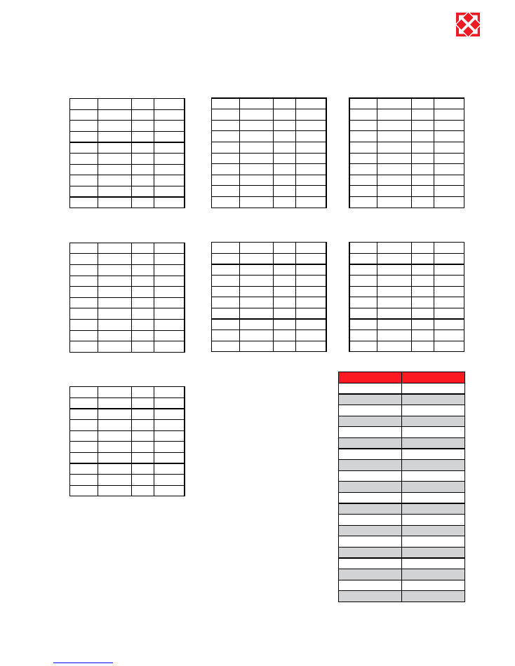
1.4 Week program scheme
Hours
Minutes
Le-
vel
Red. T2
1)
2)
3)
4)
5)
6)
7)
8)
9)
10)
Tuesday
Hours
Minutes
Le-
vel
Red. T2
1)
2)
3)
4)
5)
6)
7)
8)
9)
10)
Wednesday
Hours
Minutes
Le-
vel
Red. T2
1)
2)
3)
4)
5)
6)
7)
8)
9)
10)
Thursday
Hours
Minutes
Le-
vel
Red. T2
1)
2)
3)
4)
5)
6)
7)
8)
9)
10)
Friday
Hours
Minutes
Le-
vel
Red. T2
1)
2)
3)
4)
5)
6)
7)
8)
9)
10)
Saturday
Hours
Minutes
Le-
vel
Red. T2
1)
2)
3)
4)
5)
6)
7)
8)
9)
10)
Sunday
1.5 Defrost program
Before coil °C
Coil °C
15
-5
14
-5
13
-5
12
-6
11
-6
10
-7
9
-7
8
-8
7
-8
6
-9
5
-10
4
-10
3
-11
2
-12
1
-12
0
-13
-1
-14
-2
-14
-3
-15
-4
-15
Red. T2 = Reduced Room temperature
10
Optima 310
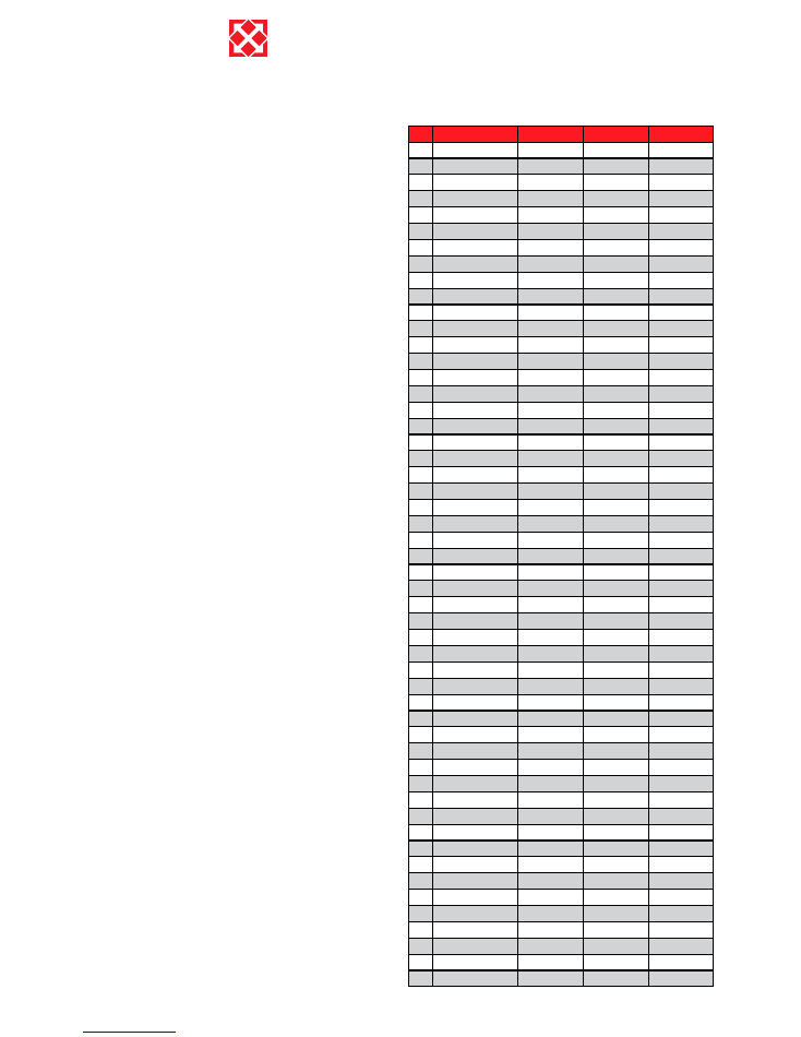
Factory setting:
Date:
Date:
Date:
1
0
2
21
3
0
4
0
5
52
6
0
7
50
8
0
9
0
10
5
11
0
12
-10
13
50
14
3
15
0
16
30
17
0
18
5
19
0
20
5
21
40
22
70
23
100
24
35
25
55
26
70
27
0
28
1
29
0
30
0
31
1
32
1
33
0
34
0
35
0
36
0
37
0
38
0
39
0
40
0
41
0
42
0
43
-3
44
0
45
20
46
3
47
0
48
0
49
70
50
5
51
0,4
52
0
1.7 Factory default scheme
1.6 Special functions
Summertime:
Changing the clock between summer- and wintertime is
done by simultaneously pressing “Enter” together with
“Arrow Up” or “Arrow Down”. This will change the clock
hour by 1 hour in the desired direction.
Contrast adjustment:
Contrast of the display can be changed by pressing the
“Info” button while the program info screen is displayed.
Use the arrows to adjust up or down. You can also enter
menu 44, press OK and then hold the info button until the
display reads “contrast adjust”, and adjust the contrast
with “arrow up/arrow down” button. After 4 seconds the
contrast adjusting menu is closed.
Program sub-version number:
Pressing “Arrow Up” when the program info screen is
displayed will also show sub-version of the controller. Or
it is possible to enter through the menu 44, press ok and
then “arrow up”

11
Optima 310
2. Function
2.1 Description Optima 310
A Combi unit is used for heating up domestic water and
supply air, to provide partial cover of the ventilation and
basic ventilation heating needs in the home.
1: Domestic water heating
The domestic water temperature is controlled by sensor
T8, which is mounted at the base of the tank. When
the need for heating of domestic water arises, the
compressor starts, the magnetic valve MA 3 and MA
6opens and the water is heated to the temperature set
(point 5 in the operating menu).
2: Room heating
By room heating the magnetic valve MA 2 and MA 5 is
activated.The room temperature is controlled by room
sensor T2, mounted on the control panel. If, for example,
this temperature has been set to 21°C, the compressor
will start up when the room temperature has fallen to
20.6°C. When the compressor has heated the room
temperature up to 21.4°C, the compressor will stop. If
the compressor cannot maintain the room temperature,
the motor valve (unit with water after heating coil) will
begin to perform temperature control (PID control) when
the room temperature has fallen to 20°C. For units with
electric after heating coils (level 1), this will cut in when
the room temperature has fallen to 20°C. When the room
temperature again reaches 20°C, the electric heat will
switch off. Units with electric pre-heating coils will control
the same way as units with after heating coils.
3: No heating needs
When there is no need for either water heating or room
heating, the compressor will stop, while the fans continue
to run. The heat in the extract air is recovered in the
counter current heat exchanger and transferred to the
supply air.
4: Defrosting
When the temperature difference between the
temperature upstream of the cooling coil and the
temperature of the cooling coil becomes too large, as
happens when ice is formed on the cooling surface, the
unit goes into defrost mode. The magnetic valve MA 4
opens and the supply air fan and the electric heating coil,
stops until the ice has melted and the cooling coil has
reached a temperature of app. 5°C. Then the magnetic
valve closes again and the supply air fan and electric
heating coil restart operation.
2.2 Extra capacity
Electric element:
If the hot water need is larger than the coverage of the
Combi, the electric heating element may be set to ON
in the main menu with a short-cut key. When the electric
heating element is ON, sensor T7, mounted in the middle
of the tank, will control heating up the upper half to the
set temperature (point 7 in the operating menu)
2.3 Operation safety
High pressure switch:
To prevent the compressor exceeding its range of
application, there is an integral high pressure switch,
which interrupts when the pressure becomes too large.
Activate the red reset button once the cause of the error
has been identified.
Circuit safety breaker:
If an error should occur in the electric heating element,
the safety breaker thermostat will disable the heater. To
reset the safety breaker the centre button of the safety
breaker must be pressed. The safety breaker is located
on the heater. (Remember to disconnect the power
supply to the unit, before any work is carried out)
Override control of supply air fan:
If the supply air temperature rises to over 45°C, the
speed of the supply air fan will begin to rise, in attempt to
stabilise the supply air temperature at 45°C.
2.4 Warnings
Filter timer
To ensure that the filters are changed, and an optimal
operation is maintained, the controller has a filter timer
(please se point 14 and 15). When the timer reaches
the chosen value the display will read “change filter” and
the red Genvex logo will flash until the filters has been
changed.
Data error
This error will be shown, if no communication is possible
between the display and controller. Please control the
cable connection on the clips 21 – 24.
Frost alert
This error is shown if a water coil is installed in the
system and the temperature of the water coil is to low.
Then there is a risk of frost damage. The controller will
stop the unit and open the valve to the water coil to keep
the coil warm.
Pressure switch error
When the high pressure switch interrupts, the display will
read “Pressure switch error” and the red Genvex logo will
flash until the red reset button is activated.
12
Optima 310
3.2 Servicing
Filters:
When the red lamp on the control panel flashes, the filters
must be changed/cleaned. Stop the unit with the switch
on the unit or the electrical panel. Open the front cover
and take out the filter. When the filter has been changed
or cleaned by shaking it and by removing the worst dirt,
switch on the unit and press the enter button on the
control panel for 10-15 seconds until the Genvex logo
starts flashing again and the equipment is back in normal
operation.
Careful handling of the plates is required. They
have sharp edges and must not be damaged.
Do not vacuum or clean at high air pressure. It
will damage the filter!
Condensate drain:
When changing the filters in the autumn season check the
condensate drain and tray for blockage by dirt. Fill water
in the condensate tray and check that the water runs out
unhindered. Should this not be the case the drain must
be cleaned. At the same time make sure that the plates of
the evaporators are clean.
Counter current heat exchanger:
Inspect the counter current heat exchanger every three
years. If it is dirty, remove it and wash in warm soapy
water and then rinse, possibly in the bathroom using the
shower head.
Fans:
Every three years check the two fan wheels for dirt. If
they are dirty they must be cleaned with a brush, bottle
washer etc. Please notice that the balance weight of the
fan wheels are not removed causing an unbalance and
thereby a higher noise level and abrasion of the fans.
Supply and extract valves:
Clean the valves by wiping with a dry cloth. Make sure
the valve does not rotate, causing a change in the air
volume.
3. Maintenance
The following instructions must be followed in order to
ensure optimum operation of the Combi:
THE POWER SUPPLY TO THE SYSTEM
MUST ALWAYS BE SWITCHED OFF BEFORE
OPENING THE COVER.
When the unit has been installed for the first time
make sure the water drains are checked after a few days
to make sure they are performing well.
Environmental considerations
When the unit is being serviced or its operation is
cancelled, please make sure to follow the guidelines
for recovery and disposal of all materials according to
local procedures and laws.
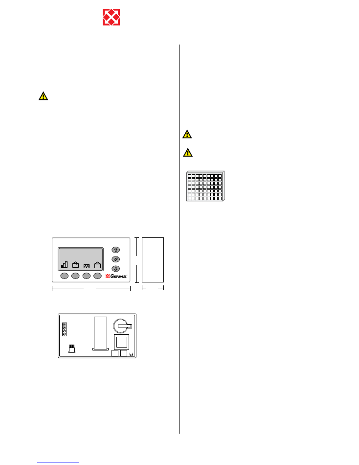
3.1 Connecting to computer
In order for the optima 310 to communicate with
the computer (data logger) the communication box
“Genvex data logger” has to be installed between
the controller and the computer. The data logger is
accessory equipment and can be required at Genvex A/S.
Cable acces (bottom rear)
back side
A: Terminal block. Power connection.
B: Room sensor T2.
C: Communication plug to computer (data logger). CTS unit
D: Data collection IC circuit (Red).
E: Processor control panel.
F: Battery.
G: IC circuit (black).
Between the unit and the control panel a light current
cable 4 x 0.25 mm2 should be mounted. The maximum
cable length is 30 m.
70
120
25
C
I
ON/OFF
Room temperature
21.5
o
C
Wednesday
12:18
24
23
22
21
D
B
C
E
F
A
G
G4 = Standard filter
(Coarse filter class G4)
F5 = Fine filter (Fine filter class F5)
F7 = Pollen filter (Fine filter class F7)

13
Optima 310
3.3 Water circuit and tank
Safety valve:
The installer have fitted a safety valve on the cold
water supply pipe for the hot water tank. This valve is a
protection of the tank against excess pressure when the
domestic water expands during heating. The non-return
valve, which is fitted before the safety valve on the cold
water pipe, prevents the water from flowing back into
the cold water pipe. This means that the pressure in the
tank will increase to the maximum pressure permitted by
the safety valve, at which point it will open and allow the
surplus water to escape. If the safety valve did not open,
the tank would burst.
To make sure that the safety valve is working properly,
it should be inspected several times a year. To do this,
press the spring-loaded arm on the safety valve and
see if water comes out of the valve. Damage caused
by a blocked safety valve is not covered by the Genvex
warranty.
Anode:
In order to prevent corrosion of the enamelled hot water
tank, the tank is fitted with a magnesium anode with a
¾“ screw plug. This anode has an estimated life time
of 2-5 years. It is nevertheless important to check that
the anode is intact at all times. This should be done by
inspecting the anode every 2 years and replacing it if
it is corroded and measures only 6-10 mm in diameter.
To inspect the anode, turn off the power supply to the
system and remove the front cover. The hot water tank
has to be drained before the anode can be unscrewed. To
do this, turn off the cold water supply and then attach a
hose to the drain cock so that the water can be disposed
of down the nearest drain. When draining the water from
the tank, turn on a hot water tap to prevent negative
pressure in the tank. When the tank is empty, the anode
can be unscrewed and inspected. When the anode has
been fitted again, close the drain cock and turn the cold
water supply back on to fill the tank with water. When the
tank is full and the cover back on, the power supply can
be switched on again.
3.4 Demounting
The following actions must be taken:
Disconnect the power supply to the unit and disconnect
other connections. Shutoff the fresh water supply valve
and connect a drain hose to the drain valve in order to
drain the water. While draining, a hot tap water valve
should be opened to avoid under pressure in the tank.
The air duct connections are uninstalled and remaining
air channels must be closed to avoid condense water
entrance to the building.
14
Optima 310
4. Fault finding
The unit is equipped with the following safety equipment:
4.1 High pressure switch:
To prevent the compressor exceeding its range of
application, there is an integral high pressure switch,
which interrupts when the pressure becomes too high.
In case of interruptions (too high pressure) the red light in
the control panel will flash and the high pressure switch
will stop the heat pump. The red light lights. Restart
the equipment by manually resetting the high pressure
switch.
For manually resetting the high pressure switch. The
front door can be removed by releasing the screws.
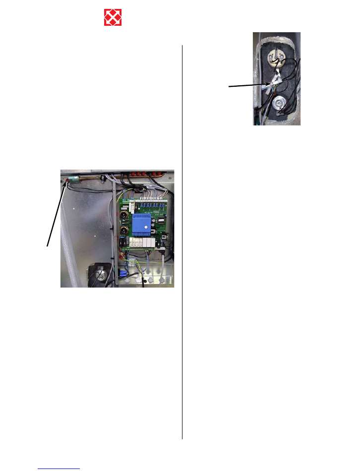
4.2 Safety breaker for electrical water
heater
The safety breaker protects the equipment against
overheating during heating with the electrical heating
element. The safety breaker is mounted on the heater. If
the adjusted value (90°) is exceeded the heating coil will
disconnect. It can be reconnected when the temperature
is below 90°. To do this, the power to the equipment must
be off, front door dismantled and the front cover of the
heating element dismantled. The reset button can now
be pressed.
Please notice: Be careful not to damage or tear the
cables to the control.
4.3 Heat pump will not operate
Unit has stopped:
Please control:
is the unit connected to the power circuit?
•
is power present in the electric outlet?
•
is the heat pump disconnected by the temperature
•
control?
is the water temperature >55°?
•
is the cable between the control and the control panel
•
installed?
has the high pressure switch switched?
•
is the filter changed?
•
Condensate running out of appliance:
Error:
Condensate drain blocked by dirt
•
4.4 Air faults
No supply air to living rooms:
Error:
Defective fan
•
Blocked bag filter
•
Fresh air grill blocked by dirt and leaves in the
•
autumn or snow and ice in the winter.
Fuse on control circuit board has blown
•
No extract air from wet rooms:
Error:
Defective fan
•
Blocked flat filter
•
Fuse on control circuit board has blown
•
Roof diffuser is blocked by snow and ice in the winter
•
Cold supply air:
Error:
Counter current heat exchanger is blocked with dirt
•
or ice
Extract fan defective
•
Extract filter blocked
•
Heat pump defect
•
Cooling coil blocked with ice
•
Control panel or circuit board defect
•
Sensor defect
•
For
RESET
press the
red pin
For
RESET
press the
white pin

15
Optima 310

Genvex World Wide:
www.genvex.dk
Intelligent ventilation appliances from
Genvex
As a ventilation specialist, our spectrum of innovative ventilation
engineering solutions: From passive ventilation appliances with
highly efficient counterflow heat exchangers, to machines with
integral heat pumps, able to heat and cool at the lowest cost.
Ceiling appliances for retrofitting in office and residential blocks
are also available.
Want to know more? Write or give us a call!
Austria
J.Pichler Lufttechnik GmbH
A-9021 Klagenfurt
Tel.: +43 (0) 463 / 3 27 69
Fax: +43 (0) 463 / 3 75 48
E-Mail: office@pichlerluft.at
Belgium
Artiklima bvba
B - 9220 Hamme
Tel.: +32 (0) 52 41 25 41
Fax: +32 (0) 52 41 29 66
E-Mail: info@artiklima.be
Croatia
Pichler & CO d.o.o.
10000 Zagreb
Tel.: + 385/ (0) 1/ 65 45 407
Fax: + 385/ (0) 1/ 65 45 409
E-Mail: pichler@zg.hnet.hr
Denmark
Genvex A/S
DK - 6100 Haderslev
Tel.: +45 73 53 27 00
Fax: +45 73 53 27 07
E-Mail: salg@genvex.dk
Germany
Novelan GmbH
D-95359 Kasendorf
Tel.: +49 (0) 92 28 / 99 60 7-0
Fax: +49 (0) 92 28 / 99 60 7-189
E-Mail: info@novelan.de
Great Britain
Total Home Environment Ltd
GB- Moreton in Marsh, GL 56 0JQ
Tel.: +44 (0) 845 260 0123
Fax: +44 (0) 1608 652490
E-Mail: genvex@totalhome.co.uk
Ireland / N.I.
ECO Systems Ireland Ltd
Co. Antrim BT54 6PH
Tel.: (UK 028) (ROI 048) +44 2076 8708
Fax: (UK 028) (ROI 048) +44 2076 9781
E-Mail: info@ecosystemsireland.com
Norway
Beam Sentralstøvsuger A/S
N - 1313 Vøyenenga
Tel.: +47 - 67 17 77 00
Fax: +47 - 67 17 77 10
E-Mail: info@beam.no
Portugal
Iberterm
PT-4475-493 Nogueira Maia
Tel: +351 229 065 123/4
Fax: +351 229 065 125
E-Mail: paulo.neto@iberterm.com
Web: www.iberterm.com
Slovenia
Pichler & CO d.o.o.
2000 Maribor
Tel.: +386/ (0) 2/460 13 50
Fax: +386/ (0) 2/460 13 55
E-Mail: pichler@pichler-co.si
Switzerland
SM-HEAG Klimatechnik AG
CH-8307 Effretikon
Tel.: +41 (0) 52 / 355 11 00
Fax: +41 (0) 52 / 355 11 05
E-Mail: info@sm-heag.ch
Published by Genvex A/S, Sverigesvej 6, DK-6100 Haderslev
Presented by: