Full Text Searchable PDF User Manual
GARW IC7
USER MANUAL

IC7 USER MANUAL
2
Contents
Overview........................................................ 3
Pinouts ........................................................ 4
Smart App………………………………….. 5
Screen settings……………………………….6
System settings……………………………....7
Page 1……………………………………8
Page 3……………………………………9
Page 4…………………………………..10
Advanced settings……………………...11
Page 4...………………………....12
Page 5………………..………….13
Page 6………………….………..14
Page 7……………….…………..15
Page 8……………….…………..16
Page 9……………….…………..17
Configuring oil temperature and oil pressure
sensors……………………………………. 18

IC7 USER MANUAL
3
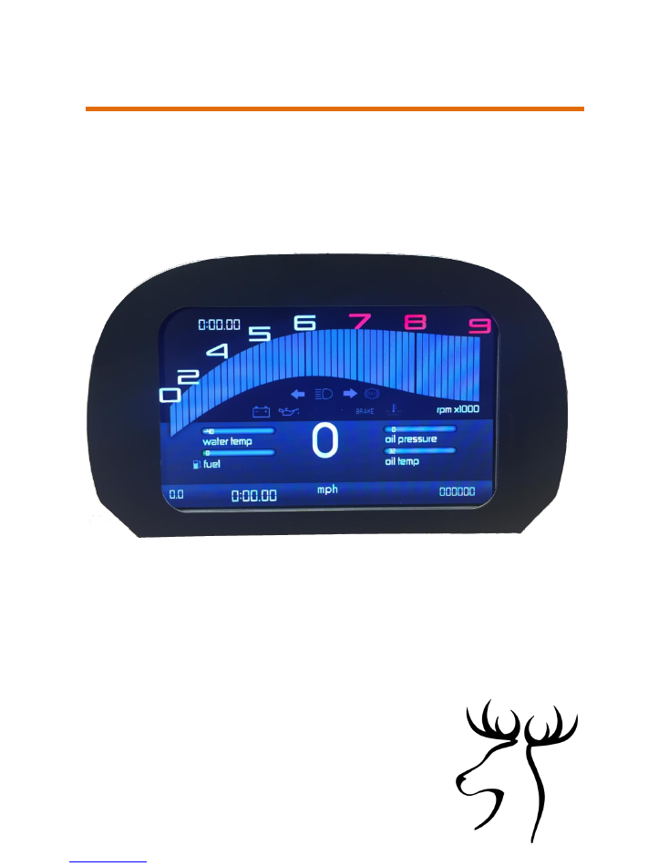
Overview
The Garw IC7 instrument cluster is a 7inch diagonal display unit designed
to display vehicle information real-time
The IC7 provides all the standard driver information expected along with
tell-tale lamps and warning symbols
All the data is collected via a wide range of inputs, configurable to
your vehicles requirements
Features
Up to 6 screens possible at one time all configured in vehicle with
individual settings for high/low warnings, units(KM/MPH,
Celsius/Fahrenheit etc.) ,colour scheme, rpm limit warning, shift indicator
Uploading of new graphics via USB
Wi-Fi connectivity for smartphone interface to change parameters read
battery and fuel level (additional features planned)
Customisable boot logo
Interfaces
7 x active low (warning lamps, trip reset)
6 x active high (tell-tale lamps for lights, turn signals)
4 x Analogue resistive inputs (for ntc temp sensors, fuel sensors)
1x Can bus
2 x Frequency inputs (1 hall, 1 hall or VR)
1 x Door switch input for booting IC7 when opening the door
2 x USB expansion for Wi-Fi, Camera, USB Drive
IC7 USER MANUAL
4
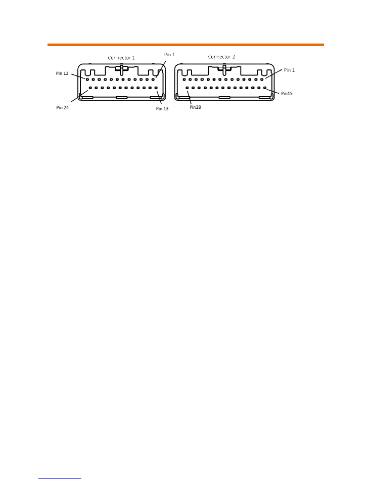
Pinouts
Connector 1
1.
Analogue 4 13. Active low input 2
2.
Battery Ground 14. Frequency 1 Hall
3.
Battery 12V
15. Active low input 3
4.
Active low input 1
16. Active low input 4
5.
Ignition
17. Frequency 2 Hall
6.
Pass through connection
18.Active high input 5
7.
CAN1 high
19.CAN1 low
8.
Active high input 1
20. Analog 6
9.
Active high input 2
21. Active low input 5
10. Frequency 2 VR
22. Active high input 6
11. Active high input 3
23. Door switch
12. Active high input 4
24. Active low input 7
Connector2
1.
Active low input Down
15. USB 5V
2.
Active low input Up
16. USB Ground
3.
Active low input Right
17. USB2 -
4.
Active low input Left
18. USB2 +
5.
Active low input Lap timer
19. USB Ground
6.
Open Drain Output 1
20. USB1 -
7.
Open Drain Output 2
21. USB1 +
8.
Open Drain Output 3
22. USB 5V
9.
Open Drain Output 4
23. USB Ground
10. Ground
24. NC
11. CAN2 high
25. NC
12. CAN2 low
26. Analogue 8
13. RS232 TX
27. Analogue 7
14. RS232 RX
28. Pass through from Connector 1

IC7 USER MANUAL
5
Smart App
The GarwIC7 instrument cluster is configured via a smart device app
Available for Android and iOS
Search app stores for GARWICX
First step is to connect to the IC7 Wi-Fi network
1. Insert the Wi-Fi adapter into any USB socket and then ensure the IC7 is
off by turning off ignition, close the door and wait 1 minute.
The next time the dash is powered the Wi-Fi adapter will be initialised
2. Once initialised the Wi-Fi adapter should blink steadily and a new
network called “Garw” should be available
3. Connect to this network with your smart device using the password
garwicxX
4. Launch the app , when successfully connected the app will display the
battery level and fuel level of your vehicle
The settings of the IC7 are accessed and modified using the directional
arrows on the app.
IC7 USER MANUAL
6
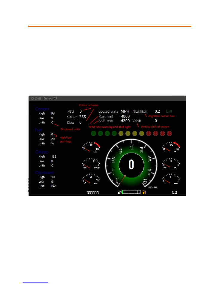
Screen settings
Each driving screen has its own settings which are access by pressing the
up arrow on the app
These settings allow changes to be made for low and high warnings, local
units for temperature and speed, colour scheme.
Left and right arrow to move between parameters
Up and down arrows to change or increment/decrement the parameter
*Not all parameters are active on all screens
Nightlight: -
When set this applies a colour overlay for night time driving.
Active when vehicle light are on
VShift:-
Moves the screen position up/down to help visibility
Colour scheme: -
depending on screen the colours of various elements can
be set with RGB values

IC7 USER MANUAL
7
System settings
Configuration of the IC7 is done through the system settings
Press and hold left or right arrow until the system settings appear
Left and right arrow to move between parameters
Up and down arrows to change or increment/decrement the parameter
Move between screens by highlighting “NEXT” in the top right of the
screen and pressing up/down for next/previous screen
Each page covers various aspects of the IC7 and allows global parameters
to be configured
There are 4 pages available in Basic view
Page 1: Real time data, Calculated gear, Software updating
Page 2: Reserved
Page 3: Driving screens configuration
Page 4: Vehicle configuration
IC7 USER MANUAL
8
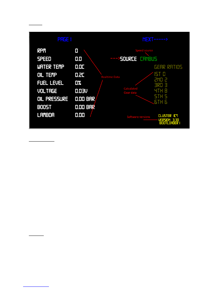
Page1
Description
Realtime Data: -
displays current values
Speed Source: -
switch between can or gps speed
Calculated gear data:-
Calibration values for the current gear indicator displayed on some driving
screens, when 1
st
gear is set to 0 calculated gear function is disabled
The value represents rpm/speed (kmh)
Software versions: -
displays product name and current software versions
installed
Page 2
Reserved
IC7 USER MANUAL
9
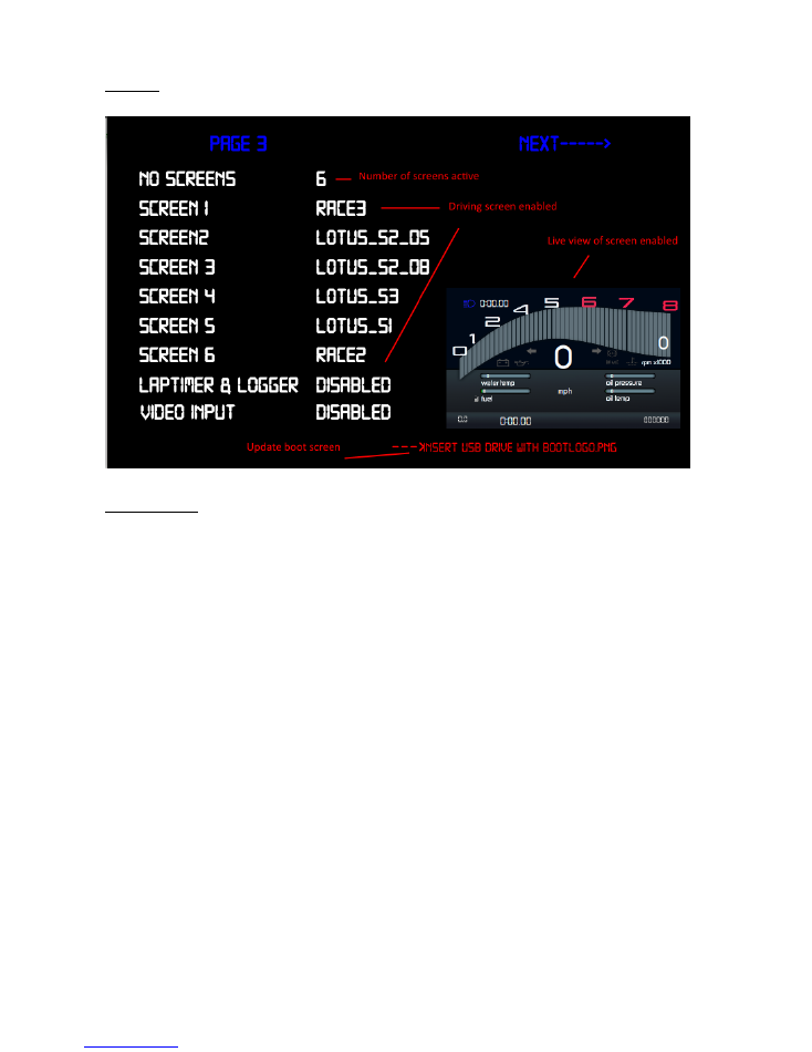
Page 3
Description
Number of screens active: -
Total number of screens enabled for
switching during driving
Driving screen enabled:
- Displays each name allocated to that positon
Laptimer & logger: -
enable/disable (in future release)
Video input: -
enable/disable video input
Live view: -
displays live the screen selected during configuration of
screens 1-6
Update boot screen:-
insert USB drive with .png image file named
“bootlogo.png” and trigger update by pressing “UP”
IC7 USER MANUAL
10
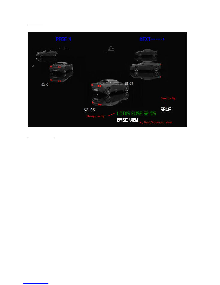
Page 4
Description
Change configuration: -
loads one of the pre-configured configurations
Save configuration: -
Saves changes to the configuration
Basic/Advanced view: -
Switches between basic view (shown above) and
advanced view

IC7 USER MANUAL
11
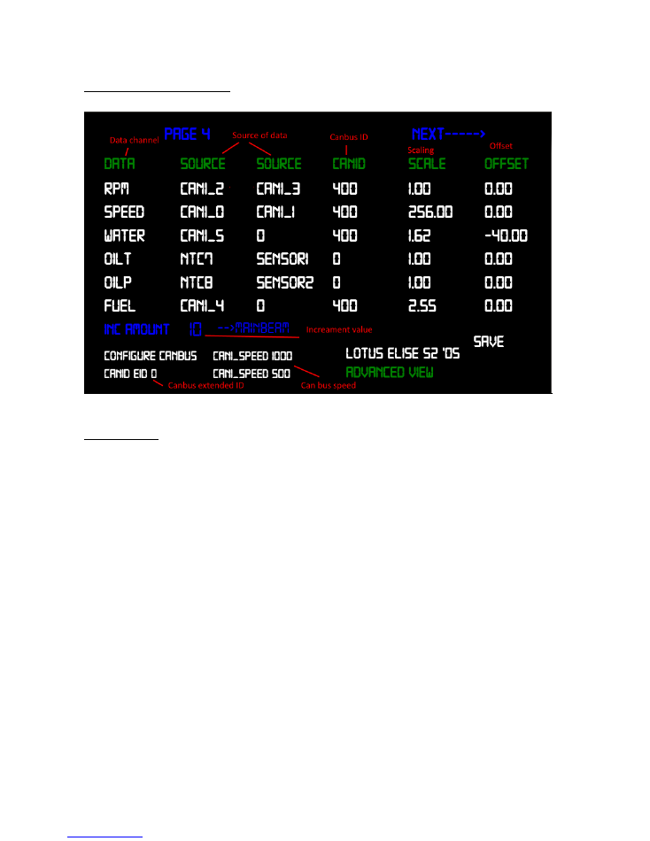
Advanced menus
In advanced view custom configurations are possible for all data channels
Additional pages are accessible once in advanced view for the following
functions
1. Manual configuration of data channels by mapping input feeds to data
channels with custom scaling and offset
2. Mapping of inputs to tell tales and warning lamps
3. Odometer correction
4. Custom sensor calibration
IC7 USER MANUAL
12
Page 4 Advanced view
Description

IC7 USER MANUAL
13
Page 5 Advanced view

IC7 USER MANUAL
14
Page 6 Advanced view

IC7 USER MANUAL
15
Page 7 Advanced view

IC7 USER MANUAL
16
Page 8 Advanced view
IC7 USER MANUAL
17
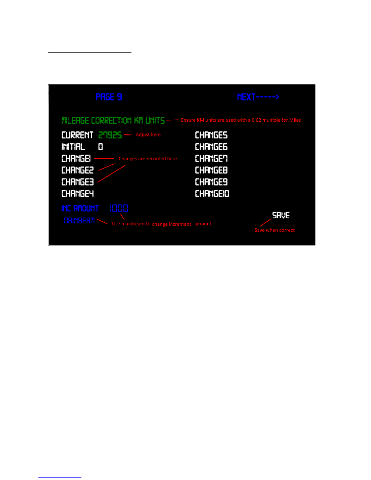
Page 9 Advanced view
Odometer correction
Adjust the current value and when sure save your changes
Ensure the value is entered in Kilometres (mileage x 0.62)
All changes are recorded for future reference
To speed up the kilometres input use your vehicles mainbeam flash to
change the increment amount 1,10,100,1000 steps at a time
IC7 USER MANUAL
18
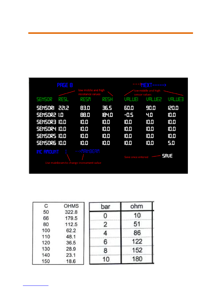
Configuring oil temperature and pressure sensors
To add additional sensors for oil temperature and pressure custom
calibration data is entered into the system settings
The technical data for the sensors is needed to enter the correct
temp/pressure vs resistance
Enter the calibration data for your oil temp and pressure sensors
Use Celsius for temp and Bar for pressure
IC7 USER MANUAL
19
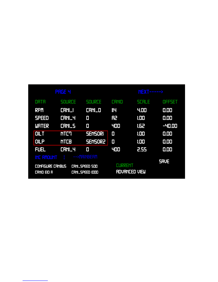
Once this data is entered highlight "SAVE" in the bottom right and
push up,
Then go to the page below and set the oil temperature and pres-
sure to the sensor calibrated above, ensure the correct NTC is
chosen
NTC7 for Analogue 7 input, NTC8 for Analogue 8 input, remember
to "SAVE" before exiting,
Your screen may look a little different but the same would apply,
If your oil pressure reading is erratic when ignition is off, set the bot-
tom value for 1 Ohm resistance
**It’s important to use gauge type sensors and not engine management
type
Gauge type will have a resistance range 0-300
Engine management type which exceeds 1000 Ohms will not function
correctly**
IC7 USER MANUAL
20
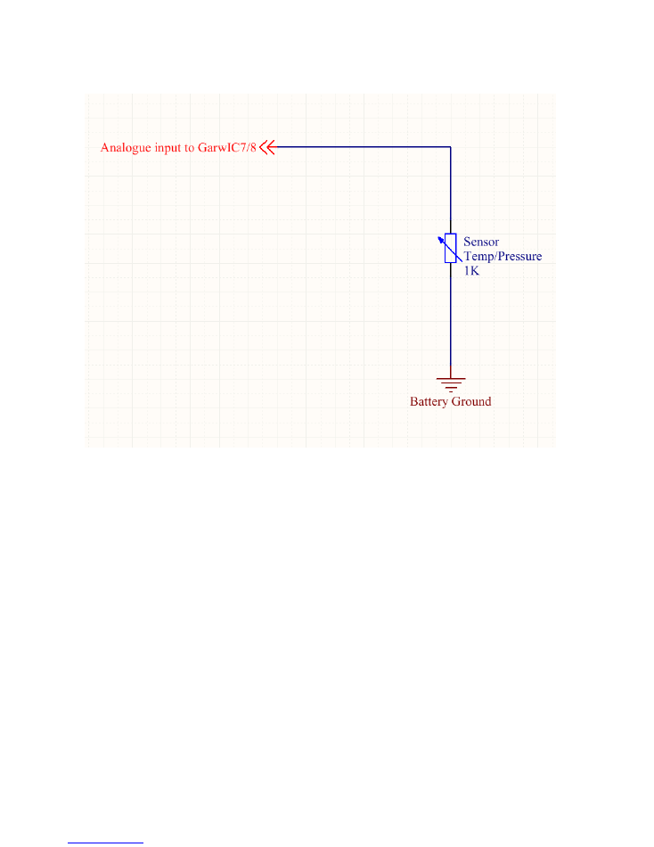
Connection diagram for Analogue inputs
Analogue pin details on page 4