Full Text Searchable PDF User Manual
SPLIT TYPE
AIR CONDITIONER
CASSETTE TYPE (50Hz)
Indoor unit
Outdoor unit
AUYA30LBLU
AUYA36LBLU
AOYA30LBTL
AOYA36LBTL
CONTENTS
SPECIFICATIONS
. . . . . . . . . . . . . . . . . . . . . .
1
DIMENSIONS
. . . . . . . . . . . . . . . . . . . . . . . . .
2
REFRIGERANT SYSTEM DIAGRAM
. . . . .
4
CIRCUIT DIAGRAM
. . . . . . . . . . . . . . . . . . . .
5
ERROR CONTENTS
. . . . . . . . . . . . . . . . . .
6
INDOOR PCB CIRCUIT DIAGRAM
. . . . . . .
. . . . .
10
OUTDOOR PCB CIRCUIT DIAGRAM
15
. . . . . . . . . . . . . . .
17
PARTS (OUTDOOR UNIT)
PARTS (INDOOR UNIT)
. . . . . . . . . . . . .
24
ACCESSORIES
. . . . . . . . . . . . . . . . . . . . . .
28
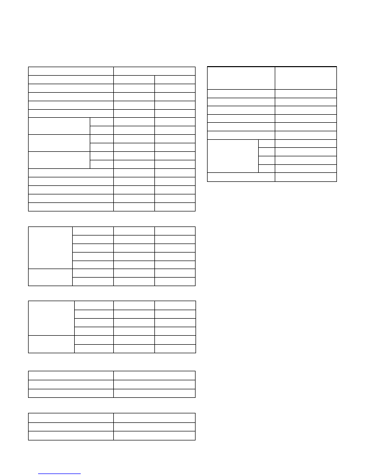
INDOOR UNIT
H x W x D
H x W x D
H x W x D
OUTDOOR UNIT
DIMENSIONS
INDOOR UNIT
DECORATION PANEL
DECORATION PANEL
Gross / Net
Gross / Net
Gross / Net
OUTDOOR UNIT
WEIGHT
POWER SOURCE
Cooling
RUNNING CURRENT
Heating
INPUT WATTS
Cooling
Heating
E.E.R.
Cooling
Heating
STARTING CURRENT
MOISTURE REMOVAL
AIRCIRCULATION OUTDOOR
FAN SPEED
Discrimination
High speed
INDOOR UNIT Med speed
Low speed
Speed
Discrimination
OUTDOOR
UNIT
TYPE
Cooling & Heating
INDOOR UNIT
AUYA30LBLU AUYA36LBLU
OUTDOOR UNIT
AOYA30LBTL AOYA36LBTL
COOLING CAPACITY
HEATING CAPACITY
288 x 840 x 840 mm
50 x 950 x 950 mm
830 x 900 x 330 mm
32 kg / 26 kg
9 kg / 5.5 kg
70 kg / 62 kg
11.6 A
12.1 A
2.65 kW
2.77 kW
3.21 kW/kW
3.61 kW/kW
13.7 A
13.3 A
3.11 kW
3.02 kW
3.21 kW/kW
3.71 kW/kW
15 A
3.0 L/hr
4,000 m3/hr
15 A
MAXIMUM CURRENT
20.0 A
17.0 A
2.5 L/hr
3,600 m3/hr
AIRCIRCULATION INDOOR
1,800 m3/hr
1,600 m3/hr
230 V 50 Hz
230 V 50 Hz
MFF-54TVM
570 r.p.m.
510 r.p.m.
470 r.p.m.
MFE-36TV
850 r.p.m.
MFF-54TVM
640 r.p.m.
510 r.p.m.
470 r.p.m.
Quiet speed
420 r.p.m.
420 r.p.m.
MFE-36TV
950 r.p.m.
8.5 kW
10.0 kW
10.0 kW
11.2 kW
ELECTRICAL DATA
COMPRESSOR TYPE
DISCRIMINATION
WEIGHT (with oil)
STANDARD REFRIGERANT
REFRIGERANT TYPE
R410A
Hermetic type, Inverter,
4 poles, 3 phase,
DC motor, Twin Rotary
5KD240XAD21
2,100 g
16.3 kg
COMPRESSOR AND REFRIGERANT
2008.06.24
1
SPECIFICATIONS
MAX PIPE LENGTH
50 m
MAX PIPE HEIGHT
30 m
Pipe length 20 m
2,100 g
FULL CHARGE
30 m
2,500 g
40 m
2,900 g
50 m
3,300 g
ADDITIONAL CHARGE
40 g/m
NOISE LEVEL
High speed
40 dB
INDOOR UNIT
Med speed
38 dB
Low speed
Cooling
Heating
36 dB
43 dB
38 dB
36 dB
Quiet speed
32 dB
32 dB
OUTDOOR
UNIT
53 dB
54 dB
55 dB
55 dB
2009.01.28
2
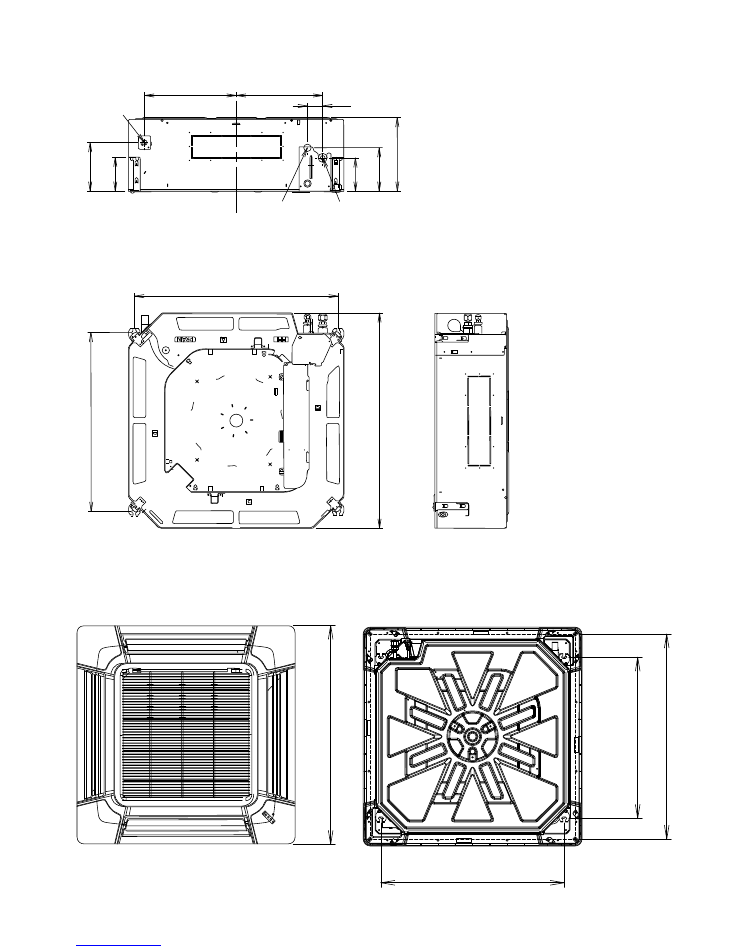
Top view
69
9
(H
an
gi
ng
b
ol
t p
os
iti
on
)
89
0
(C
ei
lin
g
op
en
in
g
m
ea
su
re
m
en
t
795 (Hanging bolt position)
Bottom view
95
0
(P
an
el
m
ea
su
re
m
en
t)
Drain pipe
Drain pipe diameter
Inside : 20 mm
Outside : 26 mm
69
9
84
0
DIMENSIONS
(Unit : mm)
INDOOR UNIT
DECORATION PANEL
Side view
Bottom view
Liquid pipe
Gas pipe
28
8
358
795
338
60
13
0
17
0
13
3
19
0
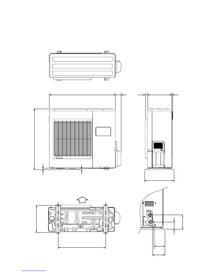
(Unit : mm)
OUTDOOR UNIT
77
900
83
0
21
9
400
330
31
12
19
6
147
170
99
37
0
650
Air Flow
2008.01.18
3
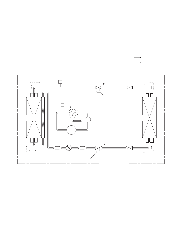
REFRIGERANT SYSTEM DIAGRAM
OUTDOOR UNIT
INDOOR UNIT
Refrigerant Pipe
15.88mm (5/8")
: Cool
Refrigerant direction
: Heat
Evaporator
Refrigerant Pipe
9.52mm (3/8")
Charging Valve
Charging
Valve
Accumulator
Strainer
Compressor
Expansion
Valve
Strainer
Condenser
4-way
Valve
Pressure
Check Valve
High
Pressure
Switch
2008.01.28
4
RED
BROWN
ORANGE
BLUE
YELLOW
GREEN
BLACK
RED
WHITE
BLACK
RED
RED
BLACK
BLACK
RED
WHITE
BLACK
YELLOW
YELLOW
G
R
E
E
N
G
R
E
E
N
RED
BLACK
WHITE
YELLOW
BROWN
G
R
AY
G
R
AY
G
R
AY
G
R
AY
G
R
AY
G
R
AY
G
R
AY
G
R
AY
G
R
AY
G
R
AY
G
R
AY
BLUE
PINK
YELLOW
ORANGE
RED
BLUE
PINK
YELLOW
ORANGE
RED
BLACK
BLACK
1 2
1 2
1 2
1 2
2 2
1 1
1 2
1 2
1 2 3 4 5 6 7 8
1 2 3 4 5 6 7 8
1 2 3 4 5 6 7 8
1 2 3 4 5 6 7 8
1 2 3
1 2 3
1 2 3
1 2 3
1
2
3
4
5
6
7
1
2
3
4
5
6
7
1
2
3
4
5
6
7
1
2
3
1
2
3
1
2
3
1
2
3
1
2
3
4
5
1
2
3
4
5
1
2
3
4
5
1
2
3
4
5
1
2
3
4
5
1
2
3
4
5
1
2
3
4
5
1
2
3
4
5
CN5
CN8
CN9
CN12
CN11
CN4
CN1
CN6
CN14
CN13
CN104
CN101
CN105
CN106
E101
E102
W105
W102
W101
1
2
3
4
5
6
1
2
3
4
5
6
FAN MOTOR
DRAIN PUMP
MOTOR
STEP MOTOR
STEP MOTOR
FLOAT SWITCH
F M
M
M
M
TERMINAL
1 2 3
1
2
3
TERMINAL
TO FRESH AIR SWITCH
( OPTION )
TO REMOTE CONTROL UNIT
INDICATOR
PCB ASSY
( OPTION )
THERMISTOR ( PIPE TEMP. )
THERMISTOR ( ROOM TEMP. )
F101 FUSE
3.15A 250V
POWER SUPPLY
PCB ASSY
CONTROLLER
PCB ASSY
( MAIN PCB )
RED
RED
BROWN
BROWN
BLUE
BLUE
BLACK
BLACK
BROWN
BROWN
BLACK
BLACK
WHITE
YELLOW
ORANGE
BLUE
BROWN
RED
BROWN
YELLOW
WHITE
BLACK
RED
RED
BLACK
BLACK
GREEN
WHITE
BLACK
WHITE
W
H
IT
E
W
H
IT
E
W
H
IT
E
B
LA
C
K
B
LA
C
K
G
R
AY
W
H
IT
E
W
H
IT
E
RED
WHITE
BLACK
ORANGE
ORANGE
BROWN
ORANGE
RED
BLACK
PURPLE
WHITE
BLUE
YELLOW
B
R
O
W
N
R
E
D
O
R
A
N
G
E
Y
E
LL
O
W
G
R
E
E
N
B
R
O
W
N
R
E
D
O
R
A
N
G
E
Y
E
LL
O
W
G
R
E
E
N
B
LU
E
P
U
R
P
LE
G
R
AY
B
LA
C
K
W
H
IT
E
B
LA
C
K
B
R
O
W
N
R
E
D
O
R
A
N
G
E
Y
E
LL
O
W
1 2 3 4 5 6 7 8 9
1 2 3 4 5 6 7 8 9
1 2 3 4 5
1 2 3 4 5
1 2 3 4 5
1 2 3 4 5
1 2 3 4 5 6 7 8 9
1 2 3 4 5 6 7 8 9
1 2
1 2
1 2 3 4
1 2 3 4
1 2
1 2
1 2
1 2
1
2
1
2
3
4
5
6
1
2
3
4
5
6
1
2
3
4
5
6
1
2
3
4
5
6
1
2
1
2
1
2
3
1
2
3
1
2
3
1
2
3
1
2
3
1
2
3
1
2
3
1
2
3
1
2
1
2
W4
CN400
CN200
CN40
CN42
CN303
CN301 W306
W307
TM302
TM301
W17
W16
TM102
TM101
TM303
W
TM304
V
TM305
U
W12
W13
W8
W7
R
C
S
L2 L1
+
-
P
N1
N2
L0
CN11
CN1
CN100
W29
W28
W25
W26
W21W9
W20
W19 W3
W18
W17
W2
W1
CN110
TM600
TM601
CN801
CN700
CN500
CN63
CN65
CN62
CN64
CN90
HIGH PRESSURE SWITCH
THERMISTOR ( COMPRESSOR TEMP. )
THERMISTOR ( OUTDOOR TEMP. )
THERMISTOR ( PIPE TEMP. )
THERMISTOR ( DISCHARGE TEMP. )
4WV 4-WAY VALVE
PMV EXPANSION VALVE
F M FAN MOTOR
FUSE 250V 25A
TERMINAL
N
L
3
2
1
POWER SOURCE
CM
COMPRESSOR
POSISTOR
CHOKE COIL
CAPACITOR
PCB ASSY
ACTPM
POWER SUPPLY
PCB ASSY
CONTROLLER
PCB ASSY
( MAIN PCB )
TRANSISTOR
PCB ASSY
( I P M )
2008.03.21
5
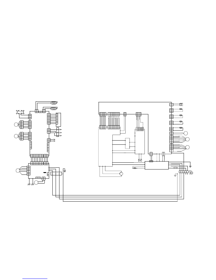
INDOOR UNIT
OUTDOOR UNIT
CIRCUIT DIAGRAM
1 2
CN7
1
2
3
4
5
CN2
1
2
3
4
5
6
CN3
1 2 3
CN102
2
1
CN103

PCB Circuit
Diagrams
not available at time of publication
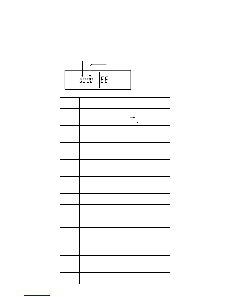
You will find this on a wired remote control LCD. (option)
If an error occurs, the following display will be shown.
("EE" will appear in the set room temperature display.)
TROUBLESHOOTING
AT A REMOTE CONTROL LCD
ERROR CONTENTS
Unit number
Error code
SU MO TU WE TH FR SA
Error code
Error contents
Wired remote controller abnormal
Indoor room temperature sensor error
Indoor heat exchanger temperature sensor (middle) error
Indoor heat exchanger temperature sensor (inlet) error
Float switch operated
Outdoor discharge pipe temperature sensor error
Outdoor heat exchanger temperature sensor (outlet) error
Outdoor temperature sensor error
Compressor temperature sensor error
2-way valve temperature sensor error
3-way valve temperature sensor error
Outdoor heat exchanger temperature sensor (middle) error
Indoor manual auto switch abnormal
Power supply frequency detection error
IPM protection
CT error
Compressor location error
Outdoor fan error
Connected indoor unit abnormal
Outdoor unit computer communication error
Indoor fan abnormal
Discharge temperature error
Exessive high pressure protection on cooling
4-way valve abnormal
Pressure switch abnormal
Compressor temperature error
Active filter abnormal
PFC circuit error
00
02
04
28
09
0C
06
0A
15
1d
1E
29
20
2A
17
18
1A
1b
1F
1c
12
0F
24
2c
16
2b
19
25
If "CO" appears in the unit number display, there is a remote control error.
Refer to the installation instruction sheet included with the remote control.
2008.04.18
15
Serial forward transfer error
Serial reverse transfer error
Communication error ( Main PCB Display PCB )
01
13
26
27
Communication error ( Display PCB Main PCB )
DANGER
This part (Choke coil) generates high voltages.
Never touch this part.
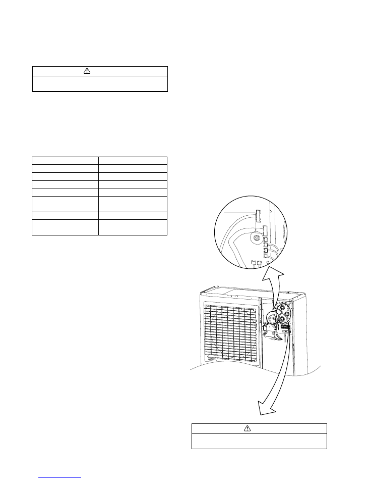
SPECIAL INSTALLATION SETTING
PUMP DOWN (Refrigerant collecting operation)
Perform the following procedures to collect the refrigerant when moving
the indoor unit or the outdoor unit.
(1) Press the push-button switch on the circuit board once.
The LED on the circuit board starts flashing (one second ON/one se-cond
OFF). This indicates the start of PUMP DOWN operation.
When the switch is pressed while the compressor is in operation, PUMP
DOWN operation starts automatically.
When the switch is pressed while the compressor is in stop, the com-pressor
starts to operate automatically, and then move on to PUMP
DOWN operation.
(2) PUMP DOWN operation continues for about 1 minute. When PUMP
DOWN operation is completed, the compressor stops automatically.
Then close the 2-way valve and 3-way valve immediately.
(3) Turn the power off.
1. Make a TEST RUN in accordance with the
installation instruction sheet for the indoor unit.
2. OUTDOOR UNIT LEDS
OUTDOOR UNIT
When a malfunction occurs in the outdoor unit, the LED on the circuit
board lights to indicate the error. Refer to the following table for the de-
scription of each error according to the LED.
CAUTION
Always turn on the power 12 hours prior to the start of the
operation in order to ensure compressor protection
LED
FLASH (0.1sec ON/0.1sec OFF)
FLASH (0.5sec ON/0.5sec OFF)
FLASH (2sec ON/2sec OFF)
FLASH (5sec ON/5sec OFF)
FLASH (0.1sec ON/2sec OFF)
FLASH (5sec ON/0.1sec OFF)
Lighting
ERROR CONTENTS
Temperature sensor error
IPM protection
Current trans. error
Outdoor fan error
Compressor rotor position cannot
be detected
ACTPM error
Overheat discharge temperature
protection
PUMP DOWN SW
2008.01.28
16
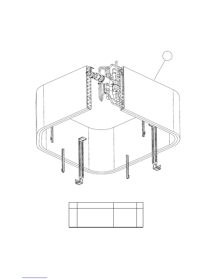
1
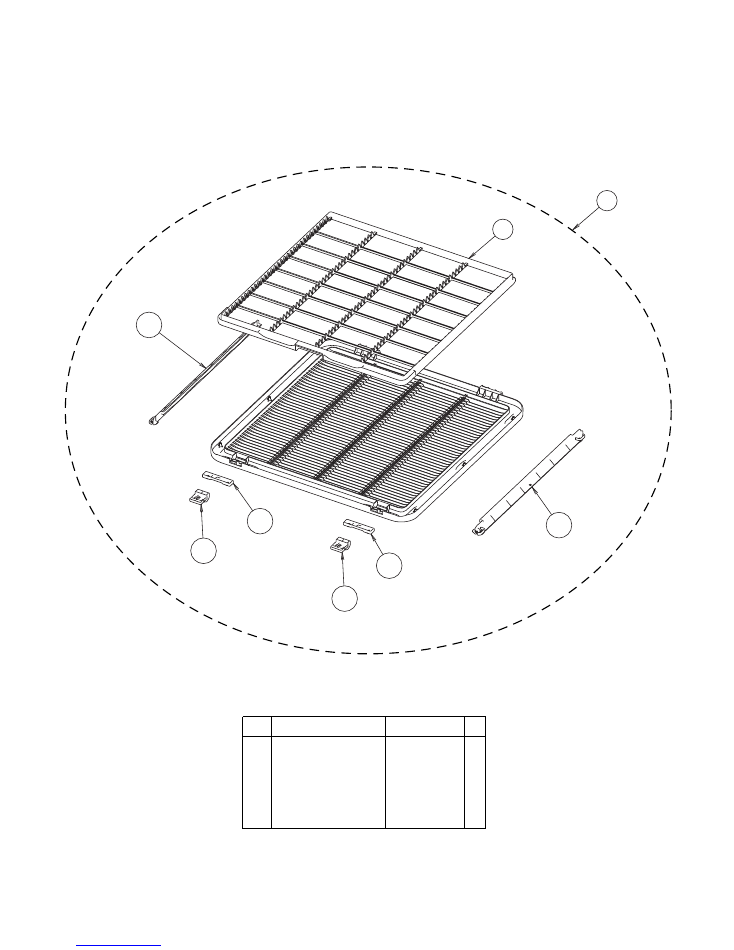
Long Life Filter
2
Intake Grille Assy
3
Filter Guide
4
Hook Bracket
5
Grille Hook
2008.06.24
PARTS
DECORATION PANEL
UTG-UGYA-W
17
9378252011
9378565012
9378253018
9378435018
9378250017
Ref. Description
Part number
2
1
3
5
4
5
4
3
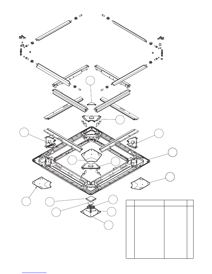
11 Decoration Panel
12 Corner Panel A
13 Corner Panel A
14 Receiver Window
15 PCB Holder
16 PCB Sube Assy
17 PCB Cover
18 Panel Cover A
19 Panel Cover B
20 Drain Cover
2008.06.24
DECORATION PANEL
UTG-UGYA-W
18
9378242012
9378243019
9378243026
9375547011
9378246010
9707372021
9378245013
9378261013
9378262010
9378359017
Ref. Description
Part number
11
19
20
17
16
12
15
12
14
13
18
18
18
12
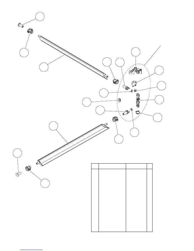
21 Flap
22 Poli Slider
31 Flap Spring
28 Joint B
25 Gear A
26 Motor Holder
24 Step motor
30 Joint Shaft
23 Joint C
2008.06.24
DECORATION PANEL
UTG-UGYA-W
Motor holder assy
19
9378254015
9375541019
27 Joint A
9378258013
9378356016
9378259010
9378256019
9378255012
9900467005
9378260016
9378357013
29 Gear B
9378257016
-- Wire (Step Motor)
9707869019
-- Wire (Step Motor)
9707869026
Ref. Description
Part number
24
25
22
23
21
30
29
27
22
27
26
30
22
31
28
23
22
21
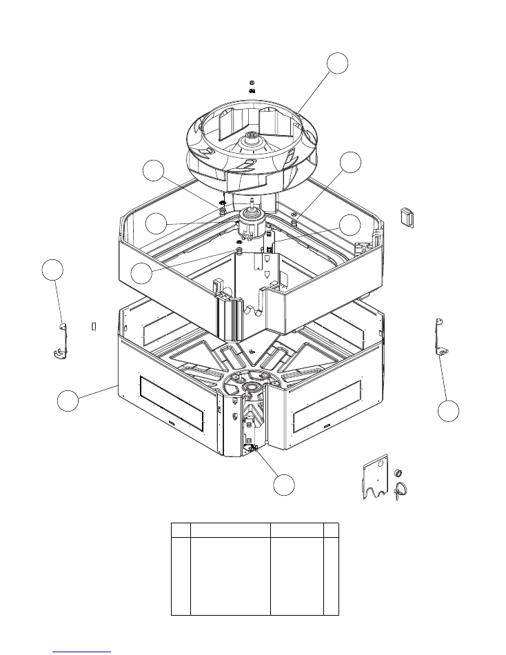
42 Hook R
INDOOR UNIT
PARTS
43 Hook L
44 Turbo Fan Assy
45 Motor, DC Brushless
46 Rubber (Motor)
41 Cabinet C
2008.06.25
20
9378197015
9378198012
9378228016
9602716005
9378223011
9378196018
Ref. Description
Part number
46
45
46
42
41
43
42
46
44
43
51 Evaporator Total Assy
21
2008.06.24
INDOOR UNIT
9378580015
-- Coupling Pipe Assy
-- Distributor Assy
9373038481
9371325446
Ref. Description
Part number
51
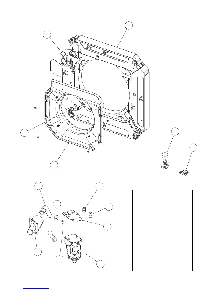
68 Drain Pan Assy
69 Bell Mouth
70 Terminal Wire Cover
-- Drain Hose Assy
71 Drain Cap
-- Drain Pan Hook
2008.06.25
22
INDOOR UNIT
9378207011
9378227019
9378548015
9377785039
9375502010
9378331013
68
70
71
69
61 Sensor Holder
62 Float Switch
64 Drain Pump Holder B
65 Rubber (Pump)
66 Drain Hose
67 Drain Port
9378329010
9900465018
63 Pump Assy
9900464011
9375518011
9378426016
9378212015
9378213012
Ref. Description
Part number
63
65
62
61
67
66
65
65
65
64
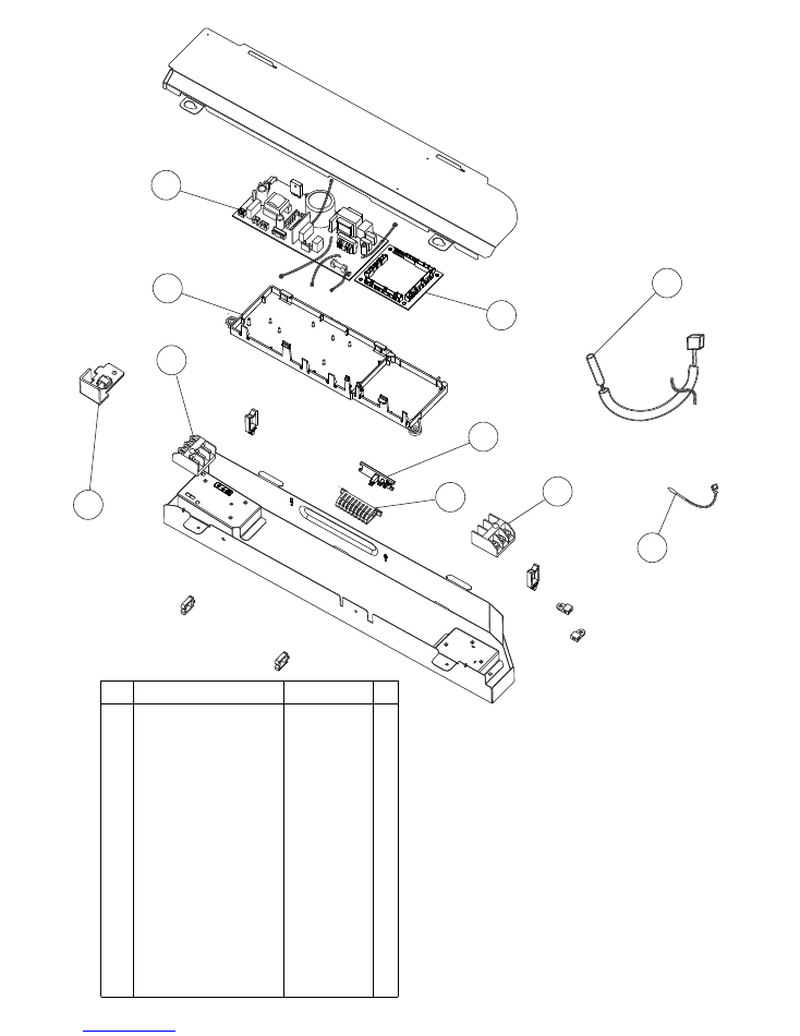
85 Terminal 3P
INDOOR UNIT
86 Terminal 3P
87 Thermistor Holder A
88 Thermistor Holder B
81 PCB Holder
82 Power PCB Assy
83 Controller PCB Assy (30)
89 Room Thermistor
90 Pipe Thermistor
84 Clamp
2008.06.25
23
9306489045
9703345012
9378206014
9378330016
9378205017
9707398083
9707393316
83 Controller PCB Assy (36)
9707393323
9900445010
9900470012
9378237018
-- Remote Control
9372266199
-- Wire (to Remote Control)
-- Wire (Control - Power) 8 lines
9703301049
9900470012
-- Wire (Control - Power) 3 lines 9372266199
Ref. Description
Part number
86
84
88
89
85
87
90
82
83
81
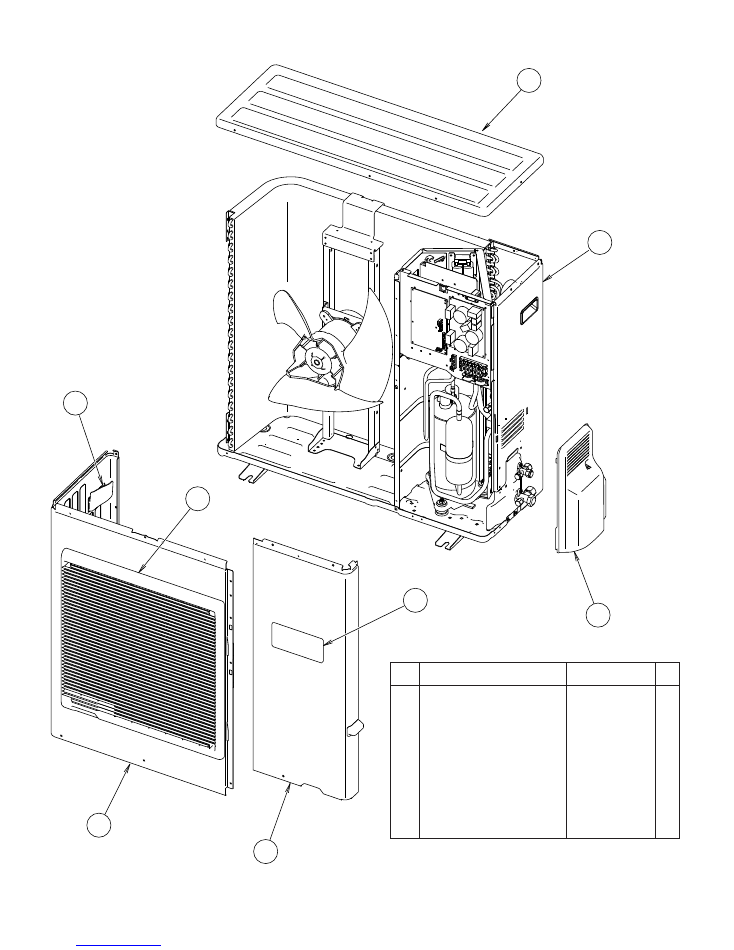
6
8
7
5
2
4
3
1
OUTDOOR UNIT
2008.04.24
24
1
Top Panel Sub Assy
9374417032
2
Front Panel
9374094066
3
Fan Guard
9374330010
4
Grip Side
9374173013
5
Service Panel Sub Assy
9374415052
6
Right Panel Sub Assy
9374416127
7
Emblem Rear
9351355005
8
Valve Cover
9374174010
Ref.
Part number
Description

14
15
12
13
11
OUTDOOR UNIT
2008.04.24
25
15
Propeller Fan Assy
9366378020
14
Fan Motor
9602717019
12
Condenser A Assy
9374433056
13
Separate Wall
9374413188
11
Base Assy
9374166138
Ref.
Part number
Description
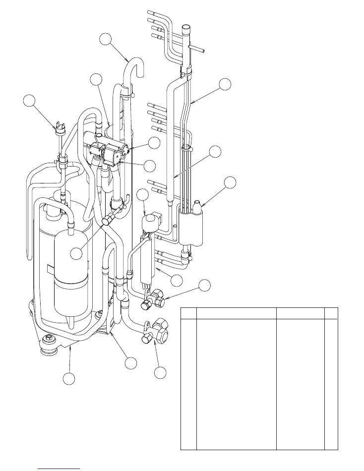
24
21
33
32
34
28
31
30
26
25
27
29
23
22
26
OUTDOOR UNIT
2008.04.24
26
Ref.
34
Strainer Assy
9372524015
31
3-Way Valve Assy
9377958013
30
3-Way Valve Assy
9377959010
27
Check Joint Assy
9372802038
25
Compressor Assy
9372558126
21
Accumulator
9385005006
22
4-Way Valve
9900164010
23
Solenoid
9970055034
24
Pressure Switch
9900186012
32
Inlet Pipe (Cond) A Assy
9373461067
26
Accumulator Support Assy 313986353804
33
Outlet Pipe (Cond) A Assy
9374266104
28
Expansion Valve Assy
9370947144
29
Coil (Expansion Valve)
9900057039
Part number
Description
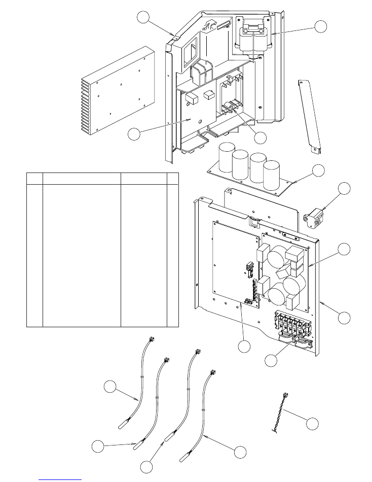
52
53
54
55
44
45
50
48
49
47
51
43
41
42
46
Connector :
White
Connector :
Yellow
Connector :
Blue
Connector :
Red
OUTDOOR UNIT
2008.04.24
27
46
PCB Case Assy
9375316020
41
Inverter Case
9375314019
43
ACTPM
9707592016
50
Thermistor
9704265012
47
Controller PCB Assy (30)
47
Controller PCB Assy (36)
9707667059
48
Power Supply PCB Assy
9707128161
45
Capacitor PCB Assy
9707257021
42
TR PCB Assy (IPM)
9707669039
44
Choke Coil
9900366018
49
Terminal
9900203023
51
Discharge Thermitor
9900461003
52
Thermistor (Outdoor)
9900463007
53
Compressor Thermistor
9900466008
54
Heat Exchanger Thermistor
9900462000
55
Wire (Pressure Switch)
9367595082
9707667066
Ref.
Part number
Description
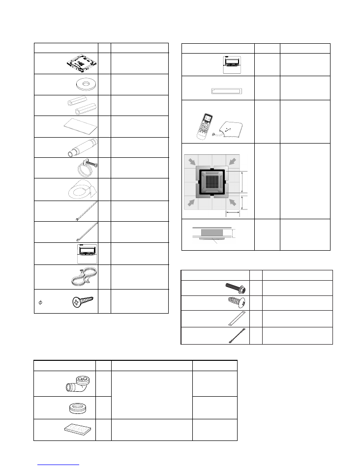
Name and Shape
Q'ty
Part number
Application
INDOOR UNIT
Installation
(seal)
1
2
1
OUTDOOR UNIT
For outdoor unit drain piping work
For filling in a gap at the entrance
of connection cords
Drain pipe
Drain cap
9303029015
313166024302
9374756018
ACCESSORIES
2009.10.13
28
Q'ty
1
8
2
1
1
1
1
3
1
1
1
2
Name and Shape
Name and Shape
Template
(Carton top)
Washer
Coupler heat
insulation
Insulation
Drain hose assy
Hose band assy
Drain pipe
insulation
Binder (Large)
Binder (Small)
Wired remote
control
Remote Control
Cord
Tapping screw
( 4 x 16)
Application
Application
For installing indoor unit
For installing indoor unit
For indoor side pipe joint
For installing drain pipe
For installing drain pipe
For installing drain pipe
For installing drain pipe
For electrincal wiring
For electrincal wiring
For connecting
remote control
For installing remote
control
OPTIONAL PARTS
DECORATION PANEL
Model name
UTB-YUD
UTR-YDZC
UTY
-LRHYA1
UTG-AGYA
UTG
-BGYA-W
Control unit on wall
Install the plate at outlet
when carrying out 3-way
direction operation.
Wireless remote control
and IR receiver unit
For ceiling hole
For making up
difference
Wired remote
contro
Air outlet shutter plate
Wireless remote control kit
Wide panel
Panel spacer
Panel spacer
242 mm
600 mm
Panel
600 mm
Indoor
unit
950 mm
Q'ty
4
4
4
2
Name and Shape
Hexigon Screw
Screw
Strap
Grille holding Wire
Application
For mounting decoration panel
For installing grille holding wire
For installing corner panel
For installing intake grille

0804G3413