Full Text Searchable PDF User Manual
INVERTER MULTI
AIR CONDITIONER
WALL MOUNTED TYPE
1
3
5
4
7
9
C O N T E N T S
SPECIFICATIONS . . . . . . . . . . . . . . . . . . .
OUTLINE AND DIMENSIONS . . . . . . . . . .
REFRIGERANT SYSTEM DIAGRAM . . . .
ERROR CONTENTS . . . . . . . . . . . . . . . . .
CIRCUIT DIAGRAM . . . . . . . . . . . . . . . . . .
INDOOR PCB CIRCUIT DIAGRAM . . . . . .
8
OUTDOOR PCB CIRCUIT DIAGRAM . . . .
PARTS (INDOOR UNIT) . . . . . . . . . . . . . .
11
ACCESSORIES . . . . . . . . . . . . . . . . . . . .
19
PARTS (OUTDOOR UNIT) . . . . . . . . . . . .
15
Indoor unit
Outdoor unit
ASY7LMACW
ASY9LMACW
AOY18LMAK2
ASY12LMACW
ASY7LMACW
ASY9LMACW
AOY24LMAM2
ASY12LMACW
1
2005.08.23
MEASUREMENT
DIMENSIONS
230 V
HIGH SPEED
DISCRIMINATION
MIDDLE SPEED
LOW SPEED
QUIET
H x W x D
257 x 808 x 187 mm
FAN MOTOR
WEIGHT
Net / Gross
8 kg / 10 kg
1,000 r.p.m.
900 r.p.m.
850 r.p.m.
800 r.p.m.
1,200 r.p.m.
1,100 r.p.m.
1,000 r.p.m.
940 r.p.m.
1,310 r.p.m.
1,260 r.p.m.
1,190 r.p.m.
1,100 r.p.m.
MFA-40GR
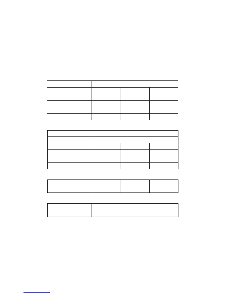
S P E C I F I C AT I O N S
COOL & HEAT
ASY9LMACW
ASY12LMACW
ASY7LMACW
TYPE
MODEL NAME
POWER SOURCE
INDOOR UNIT
ELECTRICAL DATA
2.2 kW
2.6 kW
2.7 kW
3.2 kW
1.0 L/hr
430 m3/hr
1.2 L/hr
480 m3/hr
3.5 kW
4.0 kW
1.6 L/hr
530 m3/hr
COOLING CAPACITY
HEATING CAPACITY
MOISTURE REMOVAL
AIR CIRCULATION HIGH
HIGH SPEED
LOW SPEED
NOISE LEVEL
34 dB
29 dB
36 dB
29 dB
38 dB
33 dB
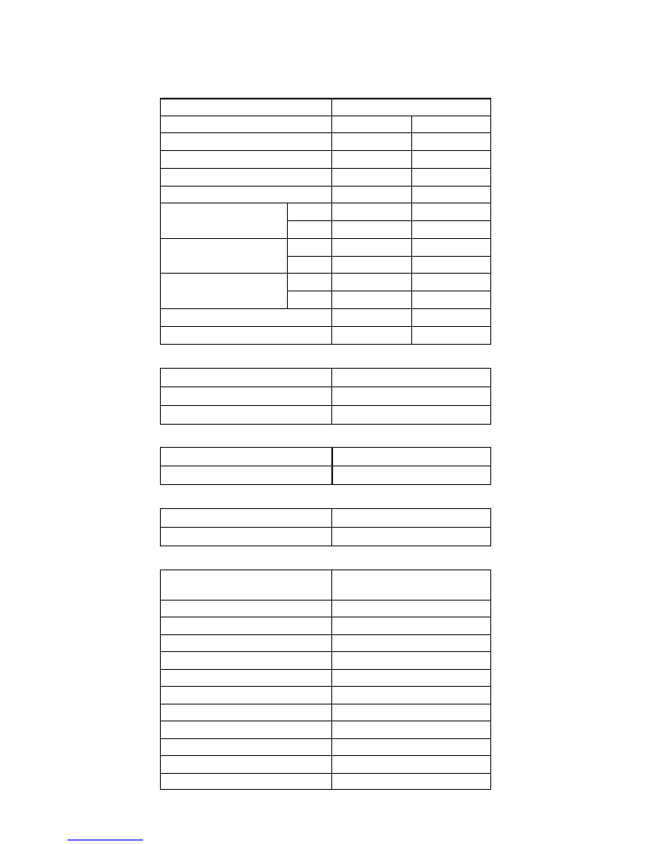
MODEL NAME
COOLING CAPACITY
HEATING CAPACITY
POWER SUPPLY
FREQUENCY
RUNNING CURRENT
INPUT
EER
AIR CIRCULATION HIGH
ELECTRICAL SPECIFICATIONS
230 V
Cooling
Heating
Cooling
Heating
Cooling
Heating
TYPE
Cooling & heating multi
AOY18LMAK2
5.5 kW
6.3 kW
7.3 A
7.3 A
1.65 kW
1.65 kW
3.33 kW/kW
3.82 kW/kW
50 Hz
230 V
50 Hz
MAX CURRENT
10.5 A
12.5 A
2,800 m
3
/hr
MAX PIPE LENGTH (each unit)
MAX PIPE LENGTH (total)
ADDITIONAL CHARGE
Chargeless
20 m
MIN. PIPE LENGTH (each unit)
5 m
MIN. PIPE LENGTH (total)
10 m
30 m
MAX ELEVATION (between indoor units)
10 m
MAX ELEVATION (between indoor and outdoor)
10 m
OUTDOOR UNIT
AOY24LMAM2
5.8 kW
6.4 kW
7.6 A
7.2 A
1.73 kW
1.64 kW
3.35 kW/kW
3.90 kW/kW
2,800 m
3
/hr
COMPRESSOR AND REFRIGERANT
FAN MOTOR
MEASUREMENT
COMPRESSOR TYPE
DISCRIMINATION
TNB220FPCMT
REFRIGERANT TYPE
R410A
STANDARD REFRIGERANT
1,900 g
WEIGHT (with oil)
14.1 kg
Hermetic type, Inverter, 4 poles,
3-phase, DC motor, Twin Rotary
650 x 830 x 320 mm
56 kg / 62 kg
WEIGHT
DIMENSIONS
MFB24JTAT
780 r.p.m.
H x W x D
Net / Gross
HIGH SPEED (HEAT)
780 r.p.m.
HIGH SPEED (COOL)
DISCRIMINATION
2
2008.12.29
NOISE LEVEL
HEAT
COOL
49 dB(A)
50 dB(A)
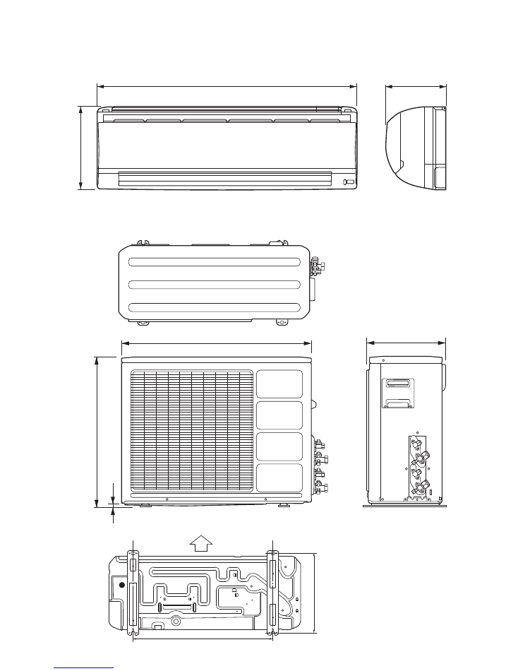
O U T L I N E A N D D I M E N S I O N S
Unit : mm
INDOOR UNIT
OUTDOOR UNIT
Air flow
Bottom
603
343
350
830
650
12
187
808
257
3
2005.06.10
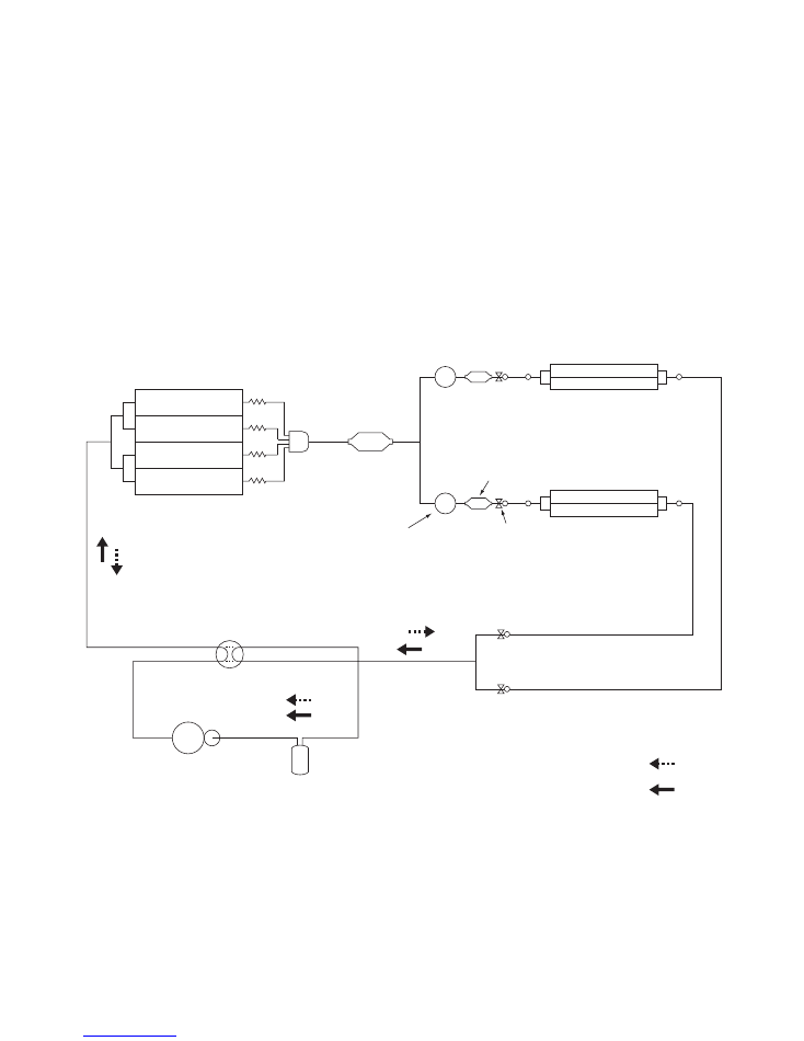
R E F R I G E R A N T
S Y S T E M D I A G R A M
A Unit
B Unit
heat exchanger
(Indoor)
heat exchanger
(Outdoor)
3-way
valve
2-way
valve
accumulator
compresser
4-way valve
COMP
electric
expansion
valve
strainer
strainer
receiver tank
EVA
EVB
HEAT
COOL
4
2005.08.19
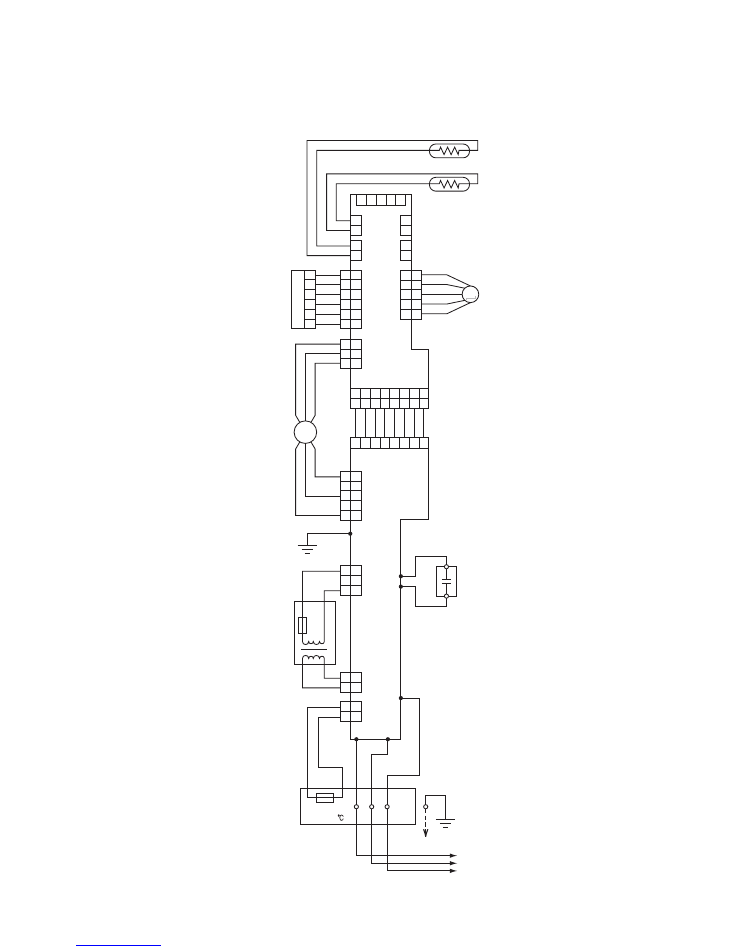
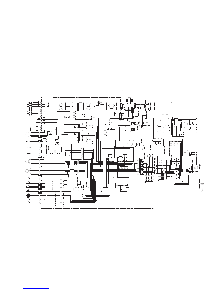
INDOOR UNIT
C I R C U I T D I A G R A M
5
2005.06.17
1
1 2 3 4 5
1 2 3 4 5 6 7 8
1 2 3 4 5 6 7 8
1 2 3 4 5 6 7 8
2
1
2
1
2
3
1
2
3
1
2
1
3
5
4
3
2
1
5
6
4
3
2
1
5
6
4
3
2
1
5
4
3
2
1
5
4
3
2
1
3
2
1
3
2
1
2
1
2
1
2
1
2
1
5
6
4
3
2
1
5
4
3
2
1
BLACK
THERMISTOR ( ROOM TEMP. )
THERMISTOR
( PIPE TEMP. )
FAN MOTOR
CAPACITOR
STEPPING MOTOR
CONT
RO
L
B
OAR
D
PO
W
ER SUP
PL
Y
BO
ARD
TRANS
FO
RME
R
BO
AR
D
DI
SP
LA
Y
FAN MO
TO
R
BLACK
GRAY
GRAY
WHITE
BLUE
PINK
YELLOW
ORANGE
RED
WHITE
WHITE
WHITE
WHITE
WHITE
W
HI
TE
WHITE
YELLOW
BLU
E
W
HI
TE
W
HI
TE
W
HI
TE
W
HI
TE
W
HI
TE
W
HI
TE
BLACK
BLACK
GREEN
ORANGE
ORANGE
PURPLE
PURPLE
RED
RED
GRAY
GRAY
BLA
CK
WHI
TE
RE
D
TH
ERM
AL
F
US
E
THERMAL FUSE
THERMAL
RED
RED
TEST
CN1
H.A. OUT
H.A. IN
CN201
CN6
CN105
W101
W106
W105
W104
W103
W102
103
CN1
01
CN102
C
N104
CN103
CN3
CN2
CN10
CN7
CN4
CN8
CN5
1
2 3
(N)
F M
M
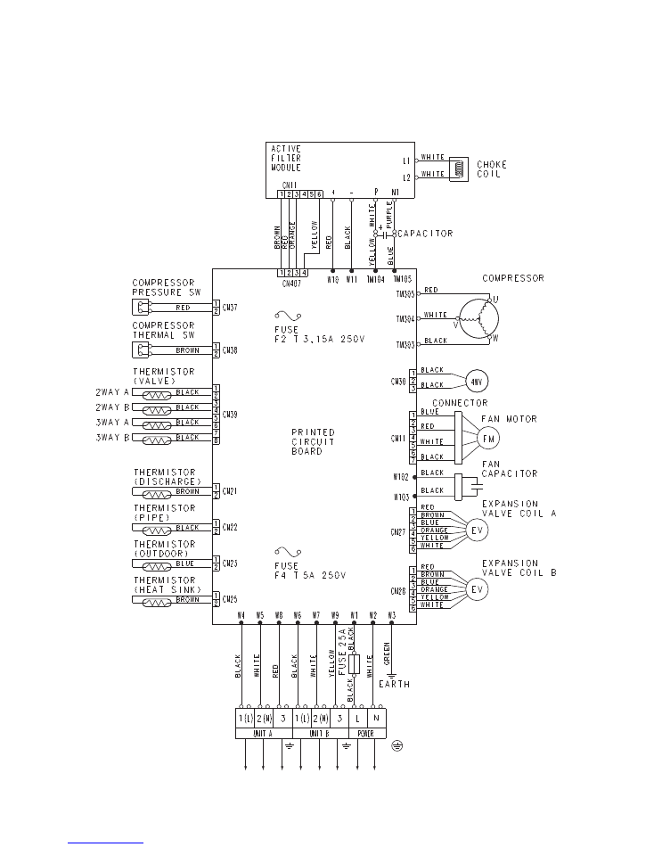
OUTDOOR UNIT
6
2005.08.23
5V
5V
+
+
+
5V
C7
10/25V
C32
0.1
<F>
C6
0.1 <F>
12V
JM1
JM5
JM4
JM3
JM2
R34
R4
R
5
R
3
R35
10K <1/10W> x 5
C1
0.1 <F>
CN8
S3P-VH
Q1
DTC124EUA
Q3
DTC124EUA
Q4
DTC124EUA
12
5
11
6
2
1
3
5V
R38
10K
<1/10W>
R8
10K
<1/10W>
5V
5V
C9
0.01
<B>
C30
0.01
<B>
R6 390 <1/10W>
R33
10K
<1/10W>
R12
10K
<1/10W>
5V
C11
0.1
<F>
5V
5V
I C2
BR93LC46
EEPROM
VCC
D0
TEST
GND
CS
SK
D1
NC
7
3
2
1
8
4
6
5
L3
BLm11
<A601>
5V
5V
R7 330
<1/10W>
I C6
PS2561-1
R9 10K
<1/10W>
C31
0.01
<B> R39
10K
<1/10W>
R10 1.0K
<1/10W>
C8
0.01
<B>
L2
BLm11
<A601>
I C7
PS2561-1
R31 330
<1/10W>
Q5
DTC124EUA
CN7
B3B-XH-AM
B2B-XH-AM
CN10
CN6
B8B-PH-K-S
5V
5V
12V
BZ1
PST1240P02A-T
B Z
R14 10K
<1/10W>
R1
10K
<1/10W>
R2 1.0K
<1/10W>
Q2
DTC124EUA
2
3
1
C2
0.1 <F>
I C 1
uPD78F0034BSGB-X39-8ET-01
or
uPD780024ASGB-X39-8ET
44
37
14
15
16
43
23
27
10
20
26
30
9
34
21
22
4
36
2
3
42
41
40
39
17
18
31
19
1
33
32
X1
X2
49
50
51
52
5
6
7
35
11
12
38
13
29
25
24
28
8
P57
RESET
P11
P10
XT2
P36
P03
P35
P34
P00
P56
P55
P54
P47
P46
P45
P44
P75
P02
P20
P21
P22
P74
P12
AVDD
VDD0
VDD1
AVREF
XT1
GND0
GND1
AGND
P12
P53
P01
P51
P52
P73
P72
P71
P70
P23
P24
I C
P25
P54
R36
X1
CST8.38MHz
L1
1
3
2
FAN MOTOR
F M
12V
5V
CN101 B3P5-VH-B
12V
12V
C104
0.1
VA102
470V
1
4
3
2
CN101-1
BLACK
CN101-3
YELLOW
CN101-5
WHITE
W106
W105
POWER SUPPLY PCB
EZ-00307HSE-P
CN103
B2B-XAS
K-1-A
B2B-XH-
AM
CN104
B2P3-VH-B
CN102
POWER TRANSFORMER
EZ-030HSE-T
THERMAL FUSE
PRIMAR
Y
SECOND
A
R
Y
CN102-3
PURPLE
CN102-1
PURPLE
CN104-1
RED
CN104
-2
RED
CN103-1
GRA
Y
CN103-2
GRA
Y
THERMAL FUSE
(10
3
)
R103
C107
0.01
W101
E
GREEN
UL1015 A
WG22
GREEN
C102
4700P
C101
4700P
C103
0.1
VA101
470V
FH101
FH102
F101
T
3.15A
250V
W102
BLACK
W103
WHITE
W104
RED
UL1015 A
WG22
BLA
CK
UL1015 A
WG22
WH
ITE
UL1015 A
WG22
RED
TERMINAL
L N 3
OUTDOOR UNIT
VA103
470V
18
10
14
3
2
5
4
1
5V
C110
0.1
<F>
I C102
H I 2002
CN105
PHR-8
UL1061 AWG26 x 8
CN105-8 WHITE
CN6-8
CN105-7 WHITE
CN6-7
CN105-6 WHITE
CN6-6
CN105-5 WHITE
CN6-5
CN105-4 WHITE
CN6-4
CN105-3 WHITE
CN6-3
CN105-2 WHITE
CN6-2
CN105-1 BLUE
CN6-1
O
I
G
+ C111
100/
25V
C108
0.1
<F>
I C101
7805
+
C106
2200
/25V
D103
1SR139
D102
MTZJ15B
+
Q101
KSD880
D101
S1VB20
R101 10K
<1/4W>
C105
2200
/35V
R102 1.0K
<1/2W>
+
C109
10/
50V
SSR101
G3MC-201PL-VD DC12V
L101
SS11V-10062
U
L1015
A
WG20
ORANGE
ORANGE
FAN CAPACITOR
7.0uF
CN7-1 RED
CN7-2 WHITE
CN7-3 BLACK
12V
12V
I C5-1 uLN2003
I C5-4 uLN2003
I C5-3 uLN2003
I C5-2 uLN2003
8
13
15
14
16
9
4
2
1
3
CN5-1 RED
CN5-2 ORANGE
CN5-3 YELLOW
CN5-5 BLUE
CN5-4 PINK
UL1061 AWG26 x 5
CN5
53325-0510
UL1061 AWG26 x 6
LOUVER
M
CN4-6 WHITE 6
CN4-4 WHITE
CN4-5 WHITE
5
4
3
2
1
CN4-2 WHITE
CN4-3 WHITE
CN4-1 RED
5V
CN4 B6B-PH-K-S
CN1 B5P-SHF-1AA
CHECKER
CN1-1
CN1-5
CN1-4
CN1-3
CN1-2
5V
5V
CN201
INDICATOR PCB
EZ-00307HSE-D
+
X201
GP1UM261RK
C202
0.1 <F>
R201 47
<1/4W>
C201
47/10V
VCC (+5V)
DATA
GND
OPERATE
TIMER
DEFROST
RED
GREEN
ORANGE
D201 SLR-325 <VC>
D202 SLR-325 <DC>
D203 SLR-325 <MC>
CN2-1 BLACK
CN2-1 BLACK
CN3-1 GRAY
CN3-2 GRAY
5V
CN2
CN3
R27 10K
<1/10W>
(1%)
R26 49.9K
<1/10W>
(1%)
ROOM THERMISTOR
PIPE THERMISTOR
C27
0.1 <F>
5V
R28 10K
<1/10W>
MANUAL AUTO
SWITCH
SW1
RESET 1
2
5
3
4
I C3
BD4742G
C25
0.1 <F>
C22
0.1 <F>
C21
0.1 <F>
R24 390
<1/10W>
R25 390
<1/10W>
5V
R22
R23
R20
R21
10K <1/10W> x 4
5V
R19
10K
<1/10W>
C16
1000P
<R>
R18 47 <1/10W>
R17 330 <1/10W>
R16 330 <1/10W>
R15 330 <1/10W>
5V
R29
10K
<1/10W>
R30 1.0K
<1/10W>
CONTROLLER PCB ASSEMBLY
ASY7LMACW : EZ-00307HSE-C
ASY9LMACW : EZ-00308HSE-C
ASY12LMACW : EZ-00309HSE-C
HEATING TEMPERATURE
CORRECTION 1
HEATING TEMPERATURE
CORRECTION 2
REMOTE CONTROL
CUSTOM CODE
HA SWITCHING
SERIAL SWITCHING
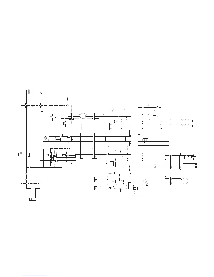
I N D O O R P C B C I R C U I T D I A G R A M
7
2009.01.21
SA100
RA-302M
L1
RCV2515-010PF05
C104
0.033
<YE>
C105
0.033
<YE>
TM100
L2
N150500K
L4
RCV2515-010PF05
5V
12V
K101
DW12D1-O ( M )
R200
ZPR0RCH400
D101
D25XB60
18V
+
-
C115
0.1
<HCP>
C415
0.01
<F>
C413
0.01
<F>
A
A
A
18V
R437, R438
270 <1/10W>
1%
x 2
5V
I C402
PS2561L-1-V
Q401
DTC114EKA
R404
510
<1/10W>
1%
W10
RED
W11
BLACK
C64
0.1
<F>
+
R68
22K
<1/10W>
KVSF687AC202
VR1
B2K
D60
DAN217U
C60
220/16V
<PJ>
R61 3.74K
<1/10W> 1%
5V
R60 1.0K
<1/10W> 1%
CT1
CT-1B
H Y I C 1
H U 2 0 0 1 R
H Y I C 2
H U 2 0 0 1 R
5V
5V
5V
R57
10K
<1/10W>
FH1
FH2
C53
0.022
<F>
R50
10K
<1/10W>
5V
R52 1.0K
<1/10W>
Q51
2SC2412K
<BQ>
R56
27K
<1/10W>
R55 1.0K
<1/10W>
C51
0.022
<F>
5V
Q52
2SC2412K
<BQ>
R53
1.0K
<1/10W>
R54
27K
<1/10W>
C54
0.022
<F>
R51 27K
<1/10W>
R58 27K
<1/10W>
5V
R19 10K
<1/10W>
R608 10K
<1/10W>
5V
JM207 0R0
I C201
BR93L46RF
5V
5V
C91
0.01
<F>
R205 10K
<1/10W>
1
2
3
6
8
4
7
5
CS
SK
D I
NC
VCC
DO
NC
GND
17
16
2
35
3
59
58
60
21
34
47
27
28
29
30
31
32
33
57
41
42
43
44
10
9
8
7
5
6
4
22
23
49
24
13
48
19
1
61
62
63
64
20
18
15
14
55
54
53
52
51
50
46
45
12
39
38
37
36
40
26
25
11
56
P63
P62
P46
P12
P50
P37
P36
P40
MD2
P11
P26
P02
P03
P04
P05
P06
P07
P10
C
P20
P21
P22
P23
P57
P56
P55
P54
P52
P53
P51
X0
X1
1
3
2
VCC
AVCC
P00
P01
P17
P13
P14
P15
P16
AVR
P24
P25
P30
P31
P32
P33
P34
P35
P60
P61
MD0
MD1
P44
P43
P42
P41
P45
RSTX
P27
AGND
GND
GND
X1
8.00MHz
<EFOEC>
C17
0.1
<F>
R72 1.0K
<1/10W>
R73 100K
<1/10W>
5V
C8
0.1
<F>
NC
GND
3
4
2
1
VDD
OUT
U
X
V
Y
W
Z
C19, C18
0.1 <F> x 2
5V
C20
4.7/
50V
<PS>
+
C95
100P
<CH>
R114 27K
<1/10W>
5V
R113
1.0K
<1/10W>
5V
Q91
2SC2412K <BQ>
R103
4.7K
<1/10W>
15V
I C13
PS8602
R102
1.6K
<1/4W>
8
6
5
2
3
1
2
3
+
-
+
-
I C11-1
uPC393
I C11-2
uPC393
7
6
5
5V
I C301 - I C306
PS2561L-1-V
x 6
R85 560
<1/10W>
R84 560
<1/10W>
R83 560
<1/10W>
R82 560
<1/10W>
R81 560
<1/10W>
R80 560
<1/10W>
1
2
3
4
1
2
3
4
1
2
3
4
1
2
3
4
1
2
3
4
1
2
3
4
C87
470P
<CH>
C89
470P
<CH>
5V-2
5V-2
C88
0.1 <F>
A
15V
R322 - R327
330 <1/10W>
x 6
R105
5.6K
<1/10W>
1%
R108
680
<1/10W>
1%
D81, D82
DAN217U x 2
2
1
3
3
2
1
R106, R104, R133
120K <1/3W> x 3
15V
+
+
C11
0.1
<F>
5V-2
A
1
2
3
I
O
G
1
2
3
I
O
G
1
2
3
I
O
G
C10
100/16V <PS>
D100
D1FL20U
C7
220/
35V
<PJ>
+
C406
220/50V
<PJ>
D401
D1FL20U
D7
D1FL20U
R5 10K
<1/10W>
D8
D1FL20U
12V
5V
+
+
C4
470/
25V
<PJ>
C5
220/
16V
<PJ>
I C407 uPC24M18
+
A
C418
10/35V
<PS>
18V
+
C6
100/16V
<PS>
T1
JPZ-200-F
9
10
12
13
15
16
8
7
6
3
2
1
5V-2
15V
5V-2
A
A
A
R303
4.7K
<1/10W>
R302 1.0K
<1/10W>
C328
2200P
<B>
A
C332
0.1
<F>
C327
0.022
<F>
I C310
PS21265
A
13
12
11
10
9
8
7
6
5
4
3
2
1
26
25
24
23
22
21
20
19
18
17
16
15
14
UP
VP I
VUFB
VUFS
VP
VP I
VVFB
VVFS
WP
VP I
VPC
VWFB
VWFS
VN I
VNC
CI N
CFO
FO
UN
VN
WN
P
U
V
W
N
5V
R40
1.0K
<1/10W>
R33
10K
<1/10W>
I C307
PS2561L
-1-V
C33
0.01
<F>
C34
0.01
<F>
4
3
2
1
R301, R305
0.033 <5W>
x 2
R304
560
<1/10W>
TM303
TM305
TM304
W
U
V
BLA
CK
WHIT
E
RED
C M
COMPRESSOR
C324 - C326
0.1 <F> x 3
15V
15V
15V
A
A
A
C316
C315
C314
C313
C312
C31
1
A
2200P <B> x 6
R328 - R333
1.0K <1/10W> x 6
A
R339
0R0
R338
0R0
R337
0R0
R336
0R0
R335
0R0
R334
0R0
FH4
FH3
C1
220P
<BN>
R2 1.0K
<RS-3W>
R1
220K
<2W>
C2 0.047
<ECQB>
R3 100
<1W>
D2
D1FL20U
C3
100/
16V
<PJ>
+
R4
330
<1/4W>
D10
RD5.6ES
<B
2>
D1
D1FL20U
R140
1.2
<1/2W>
18V
TM104
TM105
A
R201
220K
<2W>
C116 0.1
<HCP>
CR1
RE1202
0.2 / 120
12V
K11
G5SB-14
12V
12V
K17
G5NB-1A
K13
G5NB-1A
12V
D28
SLR-332
<RED>
R43 2.2K <1/10W>
5V
12V
12V
L202
BL02Rn1
L201
BL02Rn1
5V
4
1
2
3
CHOKE COIL
L=0.3MH 30A
TERMINAL
2P
L1
L2
N1
P
+
-
+
C204
1200/
450V
UL1015 AWG14
WHITE
PURPLE
BLUE
YELLOW
EMI FIL
RFC-8
1T
EMI FIL
TFC-25
15-12
2T
A
R
316 R310
R
317 R311
R
318 R312
R319 R313
R320 R314
R321 R315
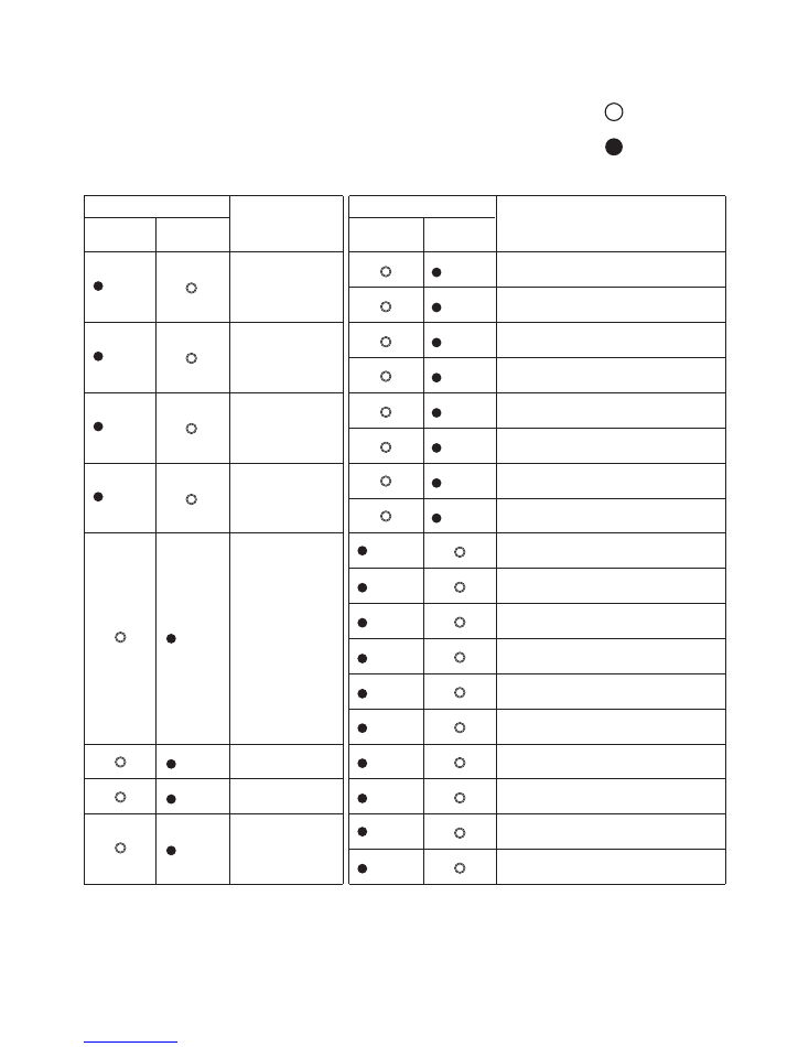
E R R O R C O N T E N T S
9
2005.06.10
INDOOR UNIT
When an error occurs, "Large division indication" is indicated first.
Secondly, "Small division indication" is indicated by pushing "Test run" button of remote controller.
: Fast flashing
: Slow flashing
Operation
(red)
Timer
(green)
Operation
(red)
Timer
(green)
Error contents
Error contents
Thermistor error
(indoor unit)
Thermistor error
(outdoor unit)
2 times
Thermistor error (room temp.)
2 times
3 times
2 times
4 times
2 times
3 times
2 times
3 times
2 times
4 times
6 times
8 times
9 times
10 times
2 times
2 times
2 times
5 times
Thermistor error (heat exchanger)
Control unit error
(indoor unit)
Control unit error
(outdoor unit)
Pressure switch
error
Inverter error
Serial error
4 times
MANUAL AUTO button error
Power source Hz decision error
Serial reverse transmission error
Serial order transmission error
Fan motor error
(indoor unit)
5 times
Lock error
6 times
2 times
3 times
4 times
5 times
r.p.m error
Discharge thermistor error
Heat exchanger thermistor error
Outdoor temperature thermistor error
Compressor thermistor error
2 way valve thermistor error
3 way valve thermistor error
Pressure switch error
Capacity error of connecting indoor unit
Outdoor unit IPM error
Compressor loter location error
LED indication
LED indication
Small division indication
Large division indication

OUTDOOR UNIT
LED
Condition
Communication abnormal
Discharge pipe thermistor abnormal
Heat exchanger thermistor abnormal
Outdoor air thermistor abnormal
2-way valve (A, B) thermistor abnormal
3-way valve (A, B) thermistor abnormal
Compressor thermistor abnormal
Pressure switch abnormal
Current trip (permanent stop)
Indoor units connection abnormal
CT abonormal (permanent stop)
Compressor location detection abormal (permanent stop)
Compressor does not start (permanent stop)
Timer reduction
1 flash
2 flashes
3 flashes
4 flashes
5 flashes
6 flashes
7 flashes
8 flashes
9 flashes
10 flashes
11 flashes
12 flashes
13 flashes
14 flashes
10
2008.04.23
2009.10.06
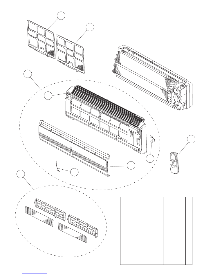
P A R T S
11
INDOOR UNIT
6
2
3
7
7
1
9
5
8
Front Panel Total Assy
9312417100
3
Air Filter
9305444014
8
Remote Control
9371190174
7
2
Intake Grille A
9330001015
1
Face Panel
9330005044
5
Grille Clamper
9306755010
6
Receiver Window
9330003019
Air Clean Filter B Assy
9312384037
--
Air Clean Filter Frame
9305445011
9
--
Remote Control Holder 9305642014
--
Electric Filter
9312153022
Ref. Description
Part number
2009.10.06
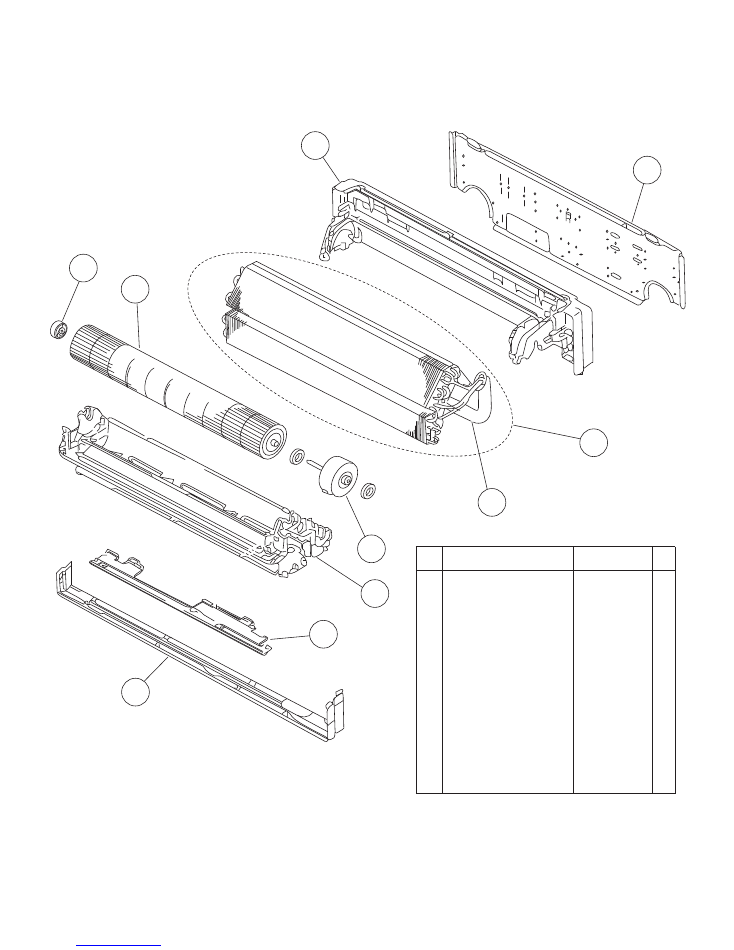
12
INDOOR UNIT
12
Base
9309755062
21
Casing Assy
9312173037
18
Shaft Holder B Assy
9303066010
13
Evaporator Sub Assy (7, 12) 9372217030
13
Evaporator Sub Assy (9) 9372217061
14
Connecting Pipe Assy
9306416010
15
Fan Motor Assy
9601844013
17
Crossflow Fan Assy
9307836015
19
Bracket (Pipe)
9330011014
11
Wall Hook Bracket
9304358008
20
Lower Cover
9330004016
Ref. Description
Part number
15
21
19
20
13
12
14
11
17
18
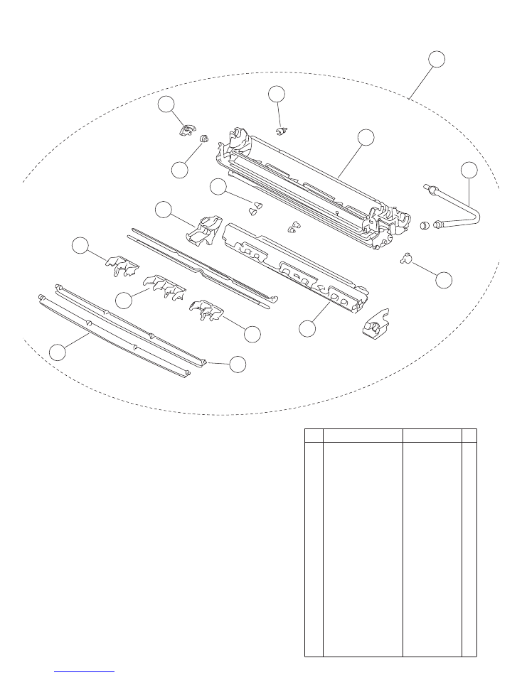
2009.01.21
13
INDOOR UNIT
Casing assy
31
Louver Z
9306058043
29
Louver A
9306055028
33
Drain Hose Assy
9310357026
25
Bushing A
9303529010
30
Louver B
9306056025
32
Louver U
9306057046
22
Casing
9306052027
21
Casing Assy
9312173037
24
Gear A
9306062002
23
Gear Bracet
9306407001
34
Drain Cap
9304150008
28
Step Motor
9900139018
26
Casing Cover LR
9306064006
27
Casing Cover B
9306121006
--
Casing Cover F
9306066000
Ref. Description
Part number
25
29
32
23
24
27
28
31
30
30
33
34
21
22
26
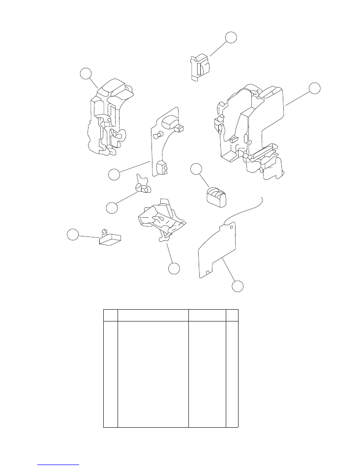
2009.01.21
14
INDOOR UNIT
41
Switch Box
9330007017
45
Power Transformer
9900028015
42
Controller PCB Assy (7)
9705289017
42
Controller PCB Assy (9)
9705289024
42
Controller PCB Assy (12)
9705289031
47
Terminal
9900040055
48
Indicator Case
9330009011
44
Lamp Cover
9330014015
46
Control Box Cover
9330008014
49
Fan Capacitor
9900089061
43
PCB Assy (Power & Indicator) 9705293014
Ref. Description
Part number
41
45
43
42
47
48
46
44
49
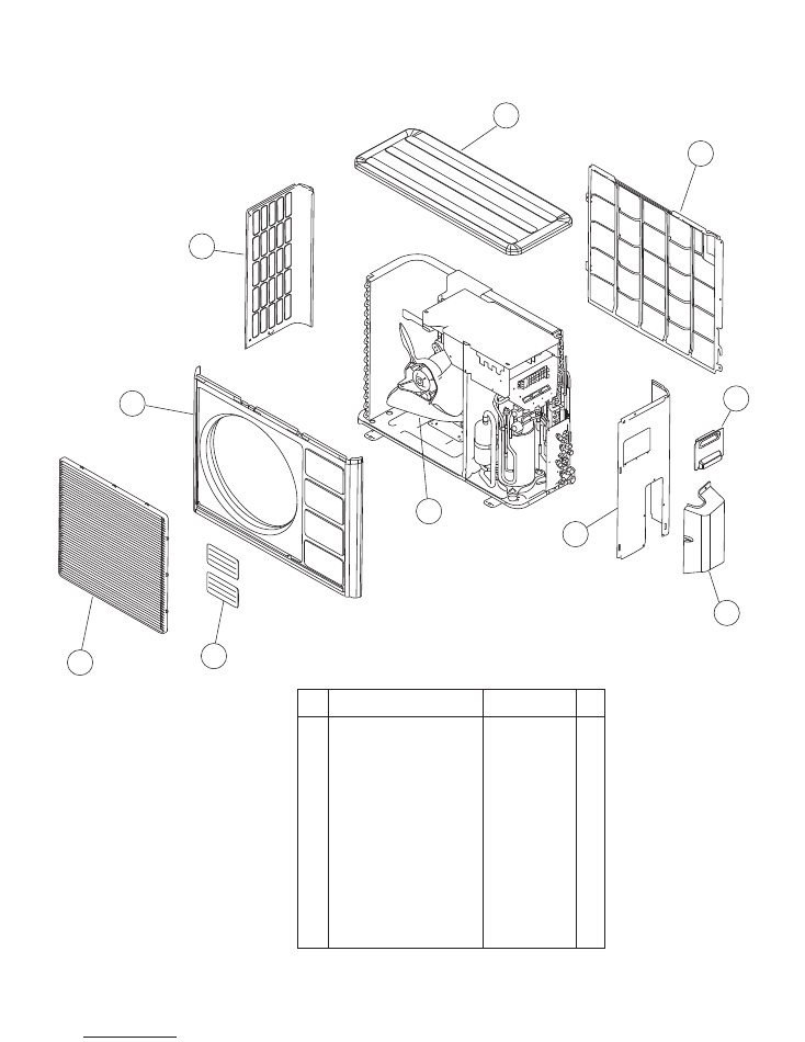
15
2008.12.11
4
Fan Guard
9371187013
5
Emblem
9351355005
3
Front Panel
9371924014
8
Connecteor Cover
9366398004
10
Propeller Fan Assy
9366378013
2
Protective Net
9371934013
1
Top Panel
9371925011
9
Valve Cover
9372796016
7
Side Panel R Sub Assy
9371926018
6
Side Panel L
9372306048
Ref. Description
Part number
5
4
3
OUTDOOR UNIT
P A R T S
6
2
1
10
9
8
7
20
23
22
22
24
21
19
11
12
18
13
15
17
16
14
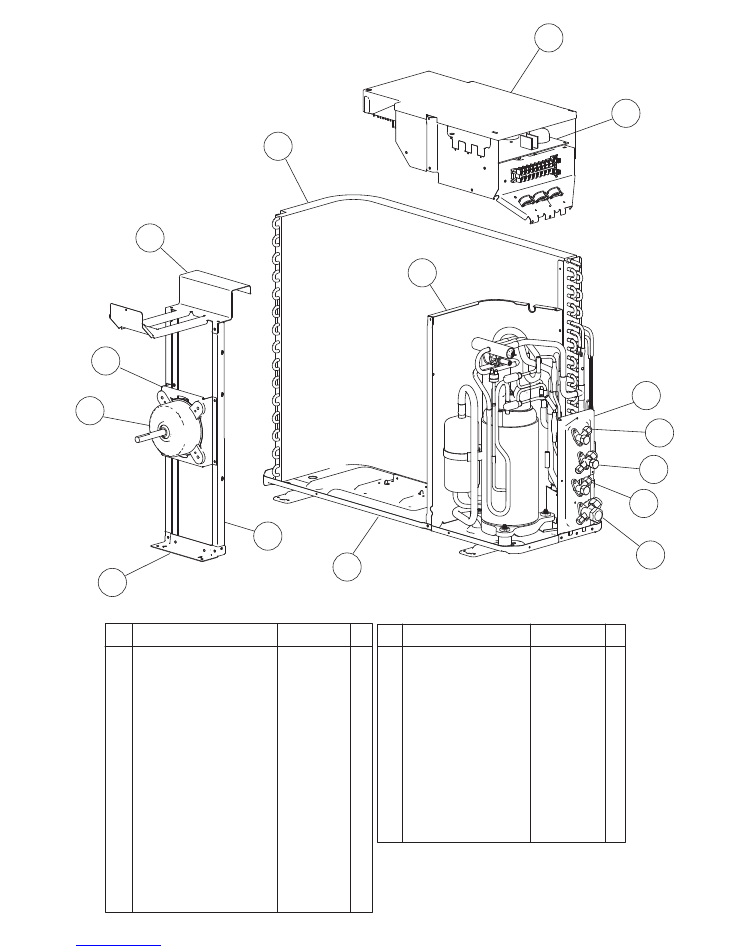
OUTDOOR UNIT
16
2008.12.03
15
Motor Bracket
9371929019
14
Motor Bracket Top
9371931012
16
Motor Bracket Center
9371930015
18
Base Assy
9371920078
23
3-Way Valve
9372205044
22
2-Way Valve
9372204054
19
Condenser Assy
9372181096
13
Motor Induct
9601671046
12
Controller PCB Assy (18LMAK2) 9707560039
12
Controller PCB Assy (24LMAM2) 9707560015
20
Separate Wall
9372795019
11
Control Cover
9372792018
24
3-Way Valve
9372205051
17
Motor Bracket Bottom
9371932019
21
Valve Plate
9371928036
Ref. Description
Part number
--
Capacitor for PCB
9705387010
--
Fan Capacitor
9900270049
--
Fuse
0600086039
--
Terminal 8P
9900203047
--
Fuse Holder
0501454012
--
Terminal 2P
9701971015
--
ACTPM
9703457012
--
Relay
9900117016
Thermistor Heat Sink
9900195014
--
Thermistor Outdoor
9703516047
--
Heat Exchanger Thermistor 9704220059
--
Ref. Description
Part number
31
32
33
34
35
36
37
38
39
40
OUTDOOR UNIT
17
2008.12.03
Ref. Description
Part number
--
Gasket (Comp)
9373266013
--
Thermal Switch
9377956019
40
Accum Support Assy
9372252017
39
Capilarry Assy
9373729211
38
Pressure Switch Assy
9373729044
36
Solenoid
9900165079
37
4-Way Valve
9900163013
--
Thermister Holder Pipe
313714262805
31
Compressor Assy
9373262015
--
Compressor Pressure Switch
9900186012
--
Compressor Thermal Switch
9373263012
--
Thermistor Valve
9900194017
--
Thermistor Discharge
9704219039
--
Special Nut M8 (Comp)
9355091008
32
Terminal Cover (Comp)
9373264019
33
Receiver Tank Assy
9373426011
34
Strainer Assy
9366602019
35
Accumulator
9368391003
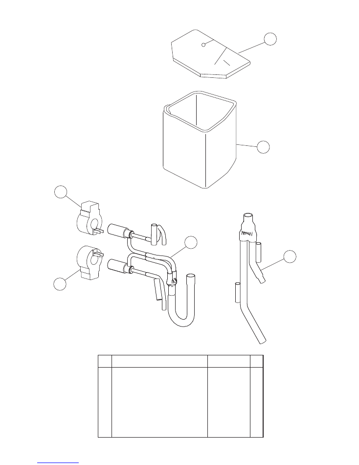
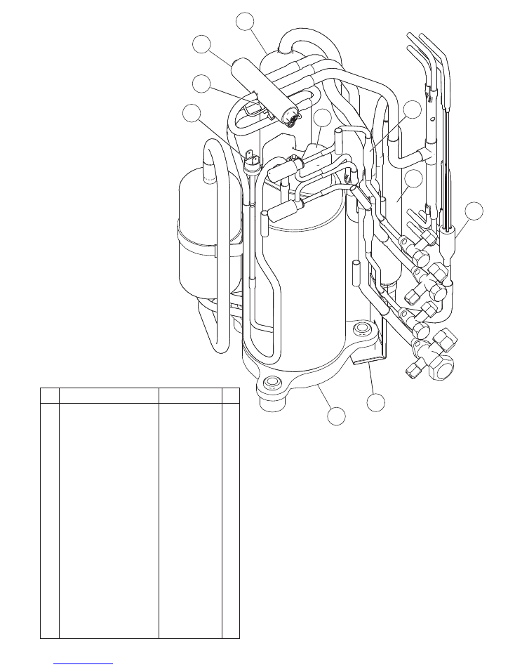
OUTDOOR UNIT
43
42
41
44
45
46
18
2008.12.01
41 Compressor Cover A
9373730019
42 Compressor Cover B
9373730026
43 Joint Pipe (3Way) Assy
9373729129
44 Expansion Valve Assy
9373729068
45 Expansion Valve Coil (White connector) 9900197018
46 Expansion Valve Coil (Red connector) 9900057022
Ref. Description
Part number
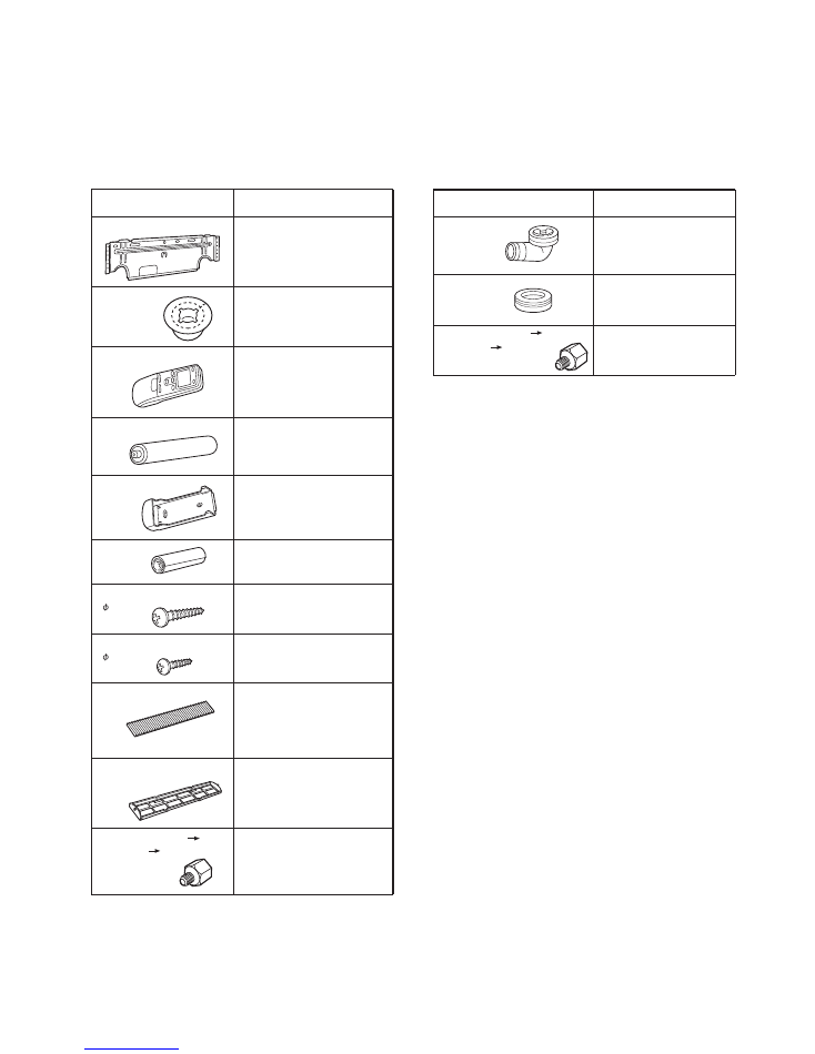
9305445011
9L model only
9370244007
9371190174
(AR-JW17)
9304358008
313714296205
0600185534
Remote control
Wall cap-B
Battery (penlight)
Wall hook bracket
INDOOR UNIT
9305642014
9308117007
301141164200
0700019036
Remote control
holder
Cloth tape
Tapping screw (big)
( 4 x 20)
Tapping screw (small)
( 3 x 12)
ELECTRIC FILTER
9310442012
DEODRANT FILTER
9310441015
Air cleaning filter
Air cleaning filter frame
Adapter D (1/2"
3/8")
12.7 mm
9.52 mm
Name and Shape
Part number
Part number
A C C E S S O R I E S
OUTDOOR UNIT
Name and Shape
313166024302
9303029015
Drain cap
Drain pipe
9370244007
Adapter D (1/2" 3/8")
12.7mm 9.52mm
19
2005.06.10

0402G2536