Full Text Searchable PDF User Manual
SPLIT TYPE
AIR CONDITIONER
DUCT TYPE (50Hz)
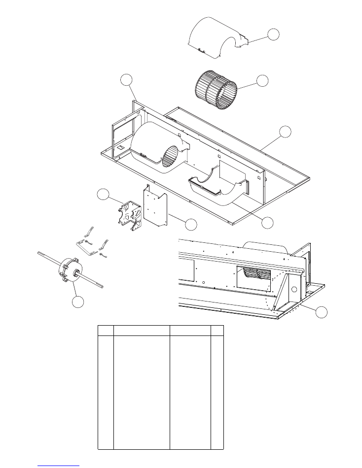
Indoor unit
Outdoor unit
ARYA36LATU
ARYA45LATU
AOYA36LATL
AOYA45LATL
CONTENTS
SPECIFICATIONS
. . . . . . . . . . . . . . . . . . . . . .
1
DIMENSIONS
. . . . . . . . . . . . . . . . . . . . . . . . .
2
REFRIGERANT SYSTEM DIAGRAM
. . . . .
4
CIRCUIT DIAGRAM
. . . . . . . . . . . . . . . . . . . .
5
ERROR CONTENTS
. . . . . . . . . . . . . . . . . .
7
INDOOR PCB CIRCUIT DIAGRAM
. . . . . . .
. . . .
10
OUTDOOR PCB CIRCUIT DIAGRAM
13
. . . . . . . . . . . . . . .
15
PARTS (OUTDOOR UNIT)
PARTS (INDOOR UNIT)
. . . . . . . . . . . . .
18
ACCESSORIES
. . . . . . . . . . . . . . . . . . . . . . .
22
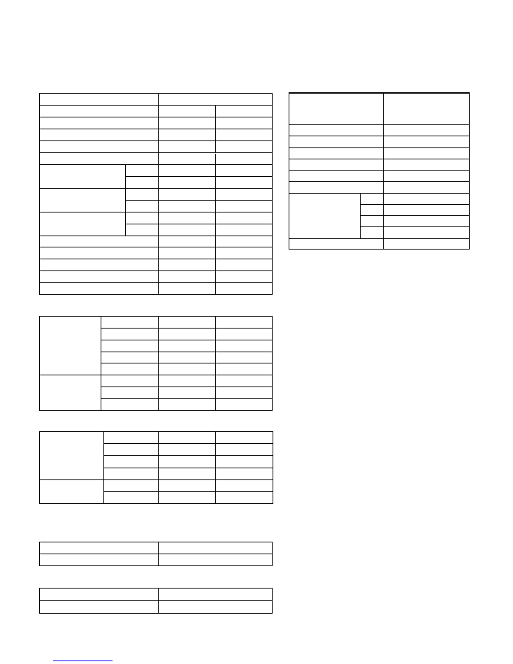
INDOOR UNIT
H x W x D
H x W x D
OUTDOOR UNIT
DIMENSIONS
INDOOR UNIT
Gross / Net
Gross / Net
OUTDOOR UNIT
WEIGHT
POWER SOURCE
Cooling
RUNNING CURRENT
Heating
INPUT WATTS
Cooling
Heating
E.E.R.
Cooling
Heating
STARTING CURRENT
MOISTURE REMOVAL
AIRCIRCULATION OUTDOOR
FAN MOTOR
Discrimination
High speed
INDOOR UNIT Med speed
Low speed
Upper fan
Lower fan
Discrimination
OUTDOOR
UNIT
TYPE
Cooling & Heating
INDOOR UNIT
ARYA36LATU ARYA45LATU
OUTDOOR UNIT
AOYA36LATL AOYA45LATL
COOLING CAPACITY
HEATING CAPACITY
270 x 1,135 x 700 mm
1,290 x 900 x 330 mm
48 kg / 41 kg
107 kg / 98 kg
13.6 A
13.2 A
3.11 kW
3.02 kW
3.21 kW/kW
3.71 kW/kW
17.0 A
16.5 A
3.89 kW
3.77 kW
3.21 kW/kW
3.71 kW/kW
15 A
3.5 L/hr
6,600 m3/hr
15 A
MAXIMUM CURRENT
20.0 A
19.0 A
3.0 L/hr
6,600 m3/hr
AIRCIRCULATION INDOOR
2,250 m3/hr
2,020 m3/hr
230 V 50 Hz
230 V 50 Hz
MFG-45RVN
1,200 r.p.m.
1,020 r.p.m.
840 r.p.m.
MFE-60PO
750 r.p.m.
MFG-45RVN
1,310 r.p.m.
1,020 r.p.m.
840 r.p.m.
Quiet
670 r.p.m.
670 r.p.m.
MFE-60PO
750 r.p.m.
850 r.p.m.
850 r.p.m.
10.0 kW
12.5 kW
11.2 kW
14.0 kW
ELECTRICAL DATA
TYPE
DISCRIMINATION
WEIGHT (with oil)
STANDARD REFRIGERANT
REFRIGERANT TYPE
R410A
Hermetic type, Inverter,
4 poles, 3 phase,
DC motor, Twin Rotary
DA420A3F-21ZA
3,350 g
23.7 kg
COMPRESSOR AND REFRIGERANT
2007.10.25
1
SPECIFICATIONS
MAX PIPE LENGTH
50 m
MAX PIPE HEIGHT
30 m
Pipe length 20 m
3,350 g
FULL CHARGE
30 m
3,850 g
40 m
4,350 g
50 m
4,850 g
ADDITIONAL CHARGE
50 g/m
NOISE LEVEL
High speed
42 dB
INDOOR UNIT
Med speed
37 dB
Low speed
Cooling
Heating
32 dB
44 dB
38 dB
33 dB
Quiet
29 dB
29 dB
OUTDOOR
UNIT
54 dB
55 dB
55 dB
56 dB
Note : Static pressure : 30Pa
Duct length : Inlet 1m, Outlet 2m
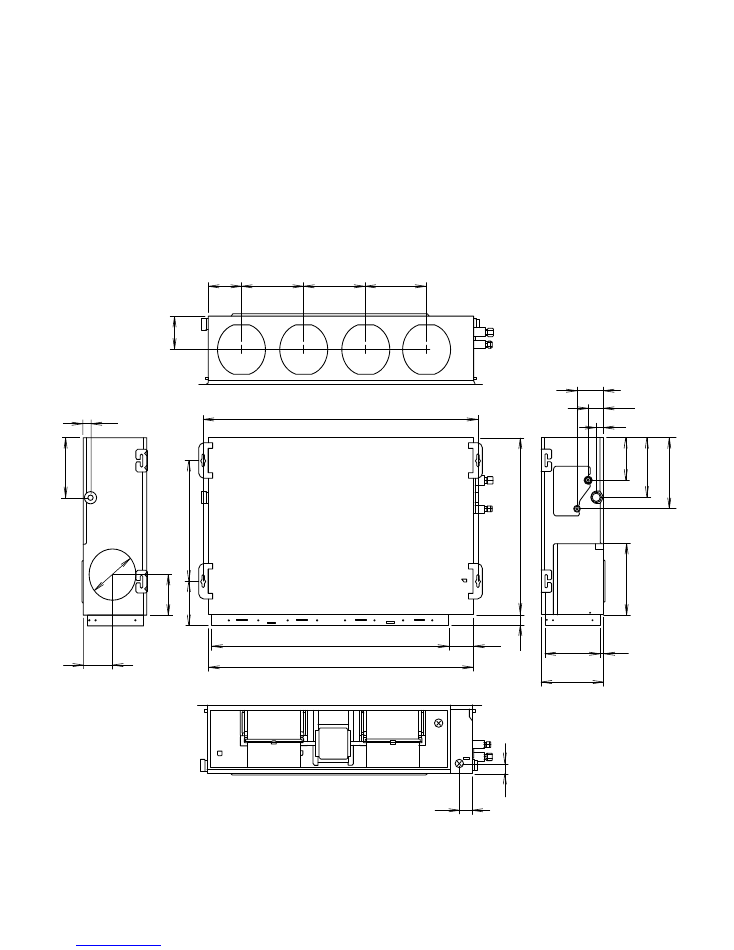
DIMENSIONS
(Unit : mm)
INDOOR UNIT
1,135
1,177
1,015
139
264
264
264
107
32
114
66
32
54
24
0
28
1
16
8
28
3
47
7
70
0
17
3
16
1
40
39
24
0
13
2
240
16
121
270
2007.01.23
2
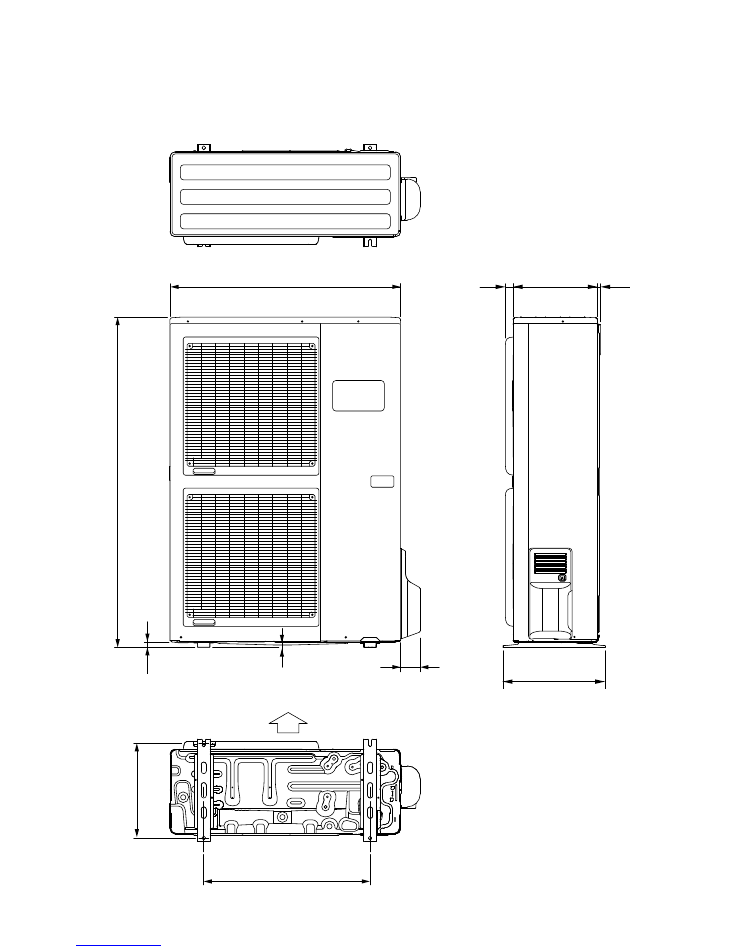
(Unit : mm)
OUTDOOR UNIT
2007.01.23
3
31
900
330
12
9
21
1,
29
0
400
650
37
0
Air Flow
77
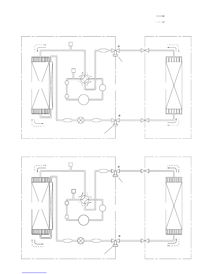
REFRIGERANT SYSTEM DIAGRAM
OUTDOOR UNIT
INDOOR UNIT
Refrigerant Pipe
15.88mm (5/8")
: Cool
Refrigerant direction
: Heat
Evaporator
Refrigerant Pipe
9.52mm (3/8")
Charging Valve
Charging
Valve
Accumulator
Strainer
Compressor
Expansion
Valve
Strainer
Condenser
Strainer
4-way
Valve
M
uf
fle
r
x
2
Pressure
Check Valve
High
Pressure
Switch
Model : ARYA36LATU / AOYA36LATL
OUTDOOR UNIT
INDOOR UNIT
Refrigerant Pipe
15.88mm (5/8")
Evaporator
Refrigerant Pipe
9.52mm (3/8")
Charging Valve
Charging
Valve
Accumulator
Strainer
Compressor
Expansion
Valve
Strainer
Condenser
Strainer
4-way
Valve
M
uf
fle
r
x
2
Pressure
Check Valve
High
Pressure
Switch
Model : ARYA45LATU / AOYA45LATL
2006.01.23
4
2007.10.25
5
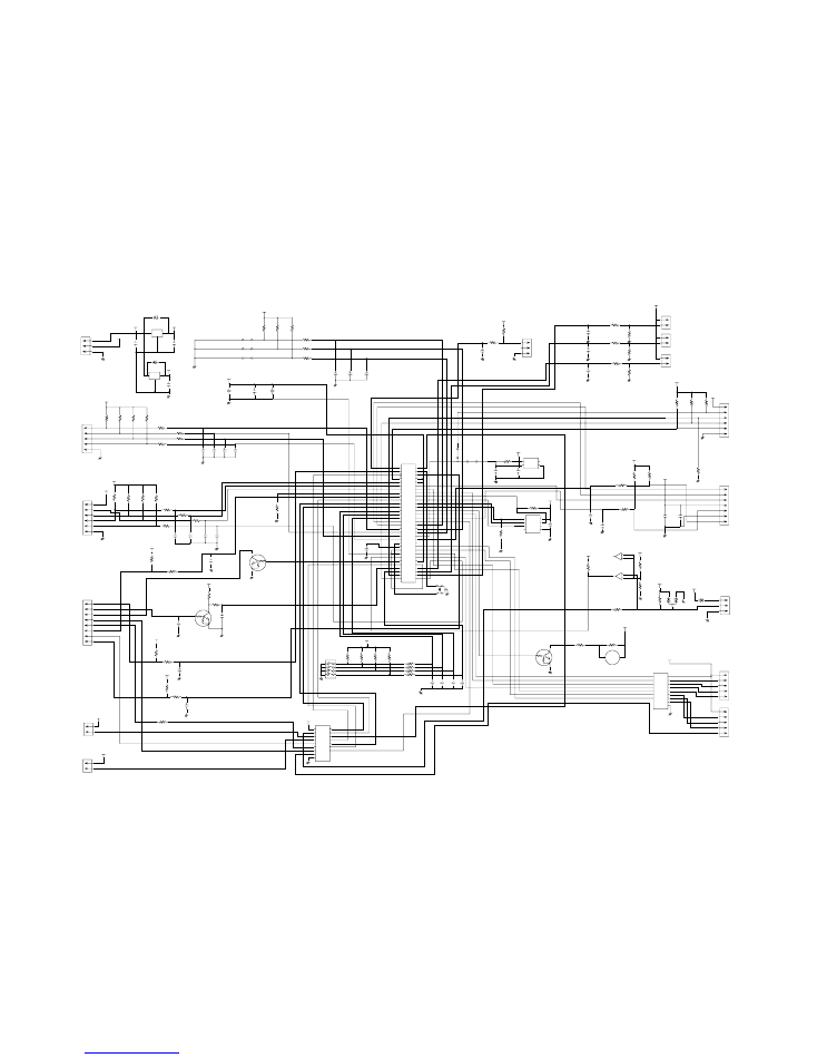
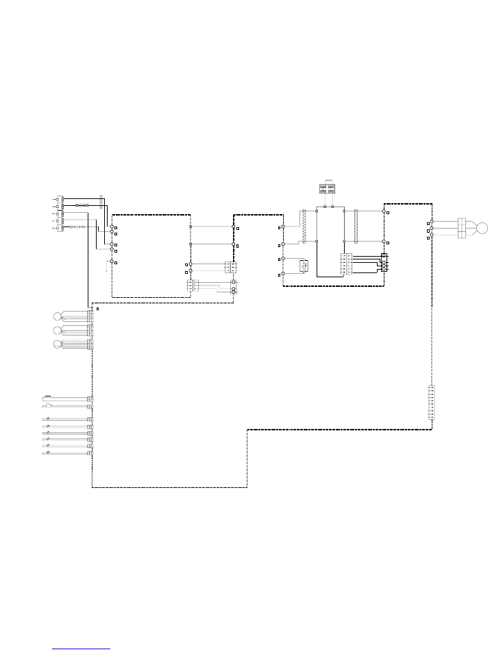
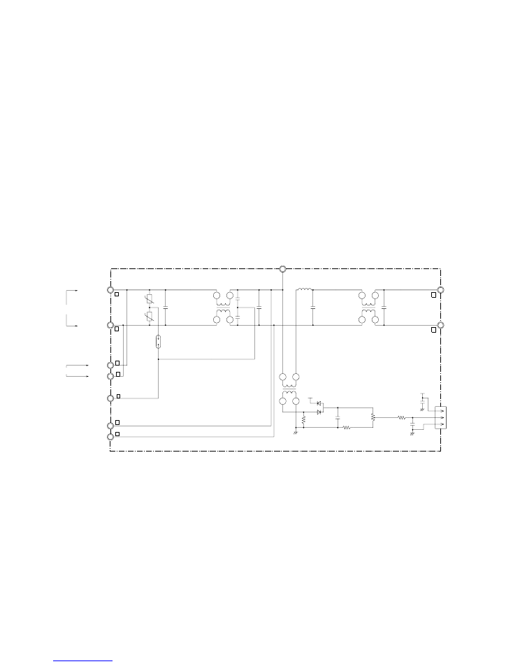
CIRCUIT DIAGRAM
BLACK
WHITE
RED
BROWN
YELLOW
WHITE
BLACK
RED
G
R
E
E
N
G
R
E
E
N
W
H
IT
E
W
H
IT
E
WHITE
RED
BLACK
G
R
AY
G
R
AY
G
R
AY
G
R
AY
G
R
AY
G
R
AY
G
R
AY
G
R
AY
G
R
AY
G
R
AY
G
R
AY
BLACK
BLACK
GRAY
GRAY
1 2 3 4 5 6 7 8
1 2 3 4 5 6 7 8
1 2 3 4 5 6 7 8
1 2 3 4 5 6 7 8
1 2 3
1 2 3
1 2 3
1 2 3
1 2 3
1 2
1 2
1 2
1 2
1
2
3
4
5
6
7
8
1
2
3
4
5
6
7
8
1
2
3
4
5
6
1
2
3
4
5
6
1
2
1
2
3
1
2
3
4
5
6
7
1
2
3
1
2
3
1
2
1
2
1
2
3
1
2
3
4
5
1
2
3
4
5
1 2
1 2
1 2 1 2
CN7 CN8
CN5
CN4
CN1
CN104
CN101
CN102 CN103 CN108
E101 E102
W105
W101
W102
C
N
10
6
C
N
10
5
C
N
10
C
N
11
C
N
9
C
N
12
C
N
14
C
N
13
C
N
6
C
N
3
TERMINAL
TERMINAL
TO REMOTE CONTROL UNIT
TO OUTDOOR UNIT
COIL
ROOM THERMISTOR
PIPE THERMISTOR
1
2
3
1
2
3
CONTROLLER
PCB ASSY
( MAIN PCB )
F101
FUSE
3.15A
250V
POWER SUPPLY
PCB ASSY
F M
FAN MOTOR
INDOOR UNIT
OUTDOOR UNIT
2007.02.27
6
1 2
1 2
1 2
1 2
1 2
1 2
1 2
1 2
1 2
1 2
1 2
1 2
1 2 3
1 2 3
1 2 3
1 2 3
1 2 3 4
1
2
3
4
5
6
7
1
2
3
4
5
6
7
1
2
3
4
5
6
7
1
2
3
4
5
6
7
1
2
3
4
5
6
1
2
3
4
5
6
1
2
3
4
5
6
1
2
3
4
5
6
1
2
3
4
5
1
2
3
1
2
3
1
2
1
2
CN24 CN21 CN22 CN23 CN26 CN25
CN37
CN30
CN800
CN801
CN27
W200
CN34
CN1
W11
W10
W17
W16
W22
W21
W13
W12
CN407
W
W303
V
W304
U
W305
TM101
TM102
CN1
W3
W6
W7
W1
W2
W9 W8
+
-
L1
L2
P
N
YELLOW
BROWN
WHITE
BLACK
RED
YELLOW
BROWN
WHITE
BLACK
RED
RED
BROWN
BLUE
ORANGE
YELLOW
WHITE
BLACK
BLACK
RED
RED
BLACK
BROWN
BLUE
RED
BLACK
BROWN
BLACK
BROWN
RED
ORANGE
YELLOW
YELLOW
BLUE
ORANGE
ORANGE
RED
BLACK
BLACK
WHITE
BROWN
WHITE
B
LA
C
K
B
LA
C
K
W
H
IT
E
B
R
O
W
N
R
E
D
B
LA
C
K
G
R
E
E
N
W
H
IT
E
B
LA
C
K
W
H
IT
E
FUSE
25A
FUSE
10A
EARTH
EARTH
N
L
3
2
1
E V
F M
EXPANSION VALVE COIL
FAN MOTOR 2
FAN MOTOR 1
F M
4WV
SOLENOID COIL
HIGH PRESSURE SWITCH
HEAT SINK THERMISTOR
COMPRESSOR THERMISTOR
OUTDOOR THERMISTOR
TERMINAL
POSISTOR
CHOKE COIL
PIPE MIDDLE THERMISTOR
DISCHARGE THERMISTOR
PIPE THERMISTOR
FUSE
F2 T 3.15A 250V
FUSE
F4 T 5A 250V
CONTROLLER PCB ASSY
( MAIN PCB )
POWER SUPPLY PCB ASSY
ACTIVE
FILTER
MODULE
RED
WHITE
BLACK
WHITE
BLACK
RED
COMPRESSOR
CONNECTOR
R ( R )
C ( T )
S ( S )
C M
R
E
D
E102
E101
UL1015 AWG20
WHITE
UL1015 AWG20
WHITE
UL1015 AWG22
RED
UL1015 AWG22
BLACK
UL1015 AWG22
WHITE
UL1015 AWG22
YELLOW
UL1015 AWG22
BROWN
UL1015 AWG16
GREEN
UL1015 AWG16
GREEN
U
L1
01
5
A
W
G
20
B
LA
C
K
U
L1
01
5
A
W
G
20
W
H
IT
E
U
L1
01
5
A
W
G
20
R
E
D
UL1430 AWG26
GRAY
UL1430 AWG26
GRAY
UL1430 AWG26
GRAY
UL1430 AWG26
GRAY
UL1430 AWG26
GRAY
UL1430 AWG26
GRAY
UL1430 AWG26
GRAY
UL1430 AWG26
GRAY
UL1430 AWG26
GRAY
UL1430 AWG26
GRAY
UL1430 AWG26
GRAY
U
L1
43
0
A
W
G
22
W
H
IT
E
U
L1
43
0
A
W
G
22
U
L1
43
0
A
W
G
22
B
LA
C
K
BLACK
BLACK
GRAY
GRAY
CN2-1
CN2-2
CN2-3
CN2-4
CN2-5
CN15-1
CN15-2
CN15-3
CN15-4
CN15-5
CN15-6
CN3-1
CN3-2
CN3-3
CN3-4
CN3-5
CN3-6
CN4-1
CN4-2
CN4-3
CN4-4
CN4-5
CN4-6
CN4-7
CN4-8
CN1-1
CN1-2
CN1-3
CN108-1
CN108-2
CN102-1
CN102-2
CN102-3
CN103-1
CN103-2
CN106-1
CN106-2
CN105-6
CN105-5
CN105-4
CN105-3
CN105-2
CN105-1
CN104-1
CN104-2
CN104-3
CN104-4
CN104-5
CN104-6
CN104-7
CN104-8
CN101-1
CN101-2
CN101-3
CN11-1
CN11-2
CN11-3
CN11-4
CN11-5
CN12-1
CN12-2
CN12-3
CN12-4
CN12-5
CN9-1
CN9-2
CN9-3
CN14-1
CN14-2
CN14-3
CN13-1
CN13-2
CN13-3
CN13-4
CN13-5
CN13-6
CN5-1
CN5-2
CN13-7
CN7-1
CN7-2
CN8-1
CN8-2
CN6-1
CN6-2
CN10-1
CN10-2
ROOM TEMPERATURE THERMISTOR
PIPE TEMPERATURE ( MID ) THERMISTOR
REMOTE CONTROL UNIT
TERMINAL BOARD
1 2 3
EARTH WIRE
W105
W102
W101
3
2(N)
1
TERMINAL BOARD
OUTDOOR UNIT
F M
DC FAN MOTOR
NORMAL COIL
RLEY41-22
22mH 2.2A
E I B I N
E I B OUT
DRAIN PUMP
FLOAT SWITCH
HEATER
FRESH AIR
DC SUPPLY
POWER DRIVE
EMI FILTER
ZCAT1518-0730
2 T
CN1
B03B-PASK-1
WHITE
CN4
B08B-PASK-1
WHITE
CN3
B06B-PASK-1
WHITE
CN15
B06B-XASK-1
WHITE
CN2
B5P-SHF-1AA
WHITE
CN106
B2P3-VH-B-E
BLUE
CN103
B2B-XH-AM
WHITE
CN105
B5P6-VH-B
WHITE
CN102
B3B-XH-AM
WHITE
CN108
B2P3-VH-B
WHITE
CN104
B08B-PASK-1
WHITE
CN101
B03B-PASK-1
WHITE
CN13
B07B-PASK-1
WHITE
CN14
B03B-XAKK-1
BLACK
CN14
B02B-PAMK-1
GREEN
CN10
B02B-PAOK-1
ORANGE
CN11
B05B-XASK-1
WHITE
CN12
B05B-XARK-1-A
RED
CN9
B03B-XARK-1-A
RED
CN8
B02B-XASK-1-A
WHITE
CN7
B02B-XAYK-1-A
YELLOW
CN5
B02B-XAKK-1-A
BLACK
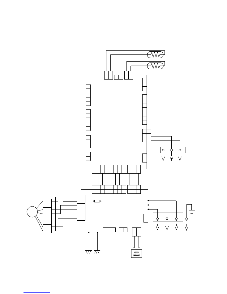
POWER SUPPLY PCB ASSEMBLY
K06AL-0605HSE-P0
CONTROLLER PCB ASSEMBLY
ARYA36LATU : K06AK-0609HSE-C1
ARYA45LATU : K06AK-0608HSE-C1
2007.10.25
7
CONTROL UNIT
ARYA36LATU : EZ-0061GHSE
ARYA45LATU : EZ-0061FHSE
INDOOR PCB CIRCUIT DIAGRAM
I C1
uPD78F0535
34
39
36
43
44
45
46
33
32
31
30
29
28
27
26
18
19
20
21
22
23
11
12
13
14
38
37
41
40
25
9
42
52
51
50
49
48
47
56
55
54
53
8
7
6
5
4
3
2
1
64
63
62
61
60
59
58
57
17
16
15
24
10
35
AVDD
AVREF
VDD0
VDD1
I C
RST
P00
P34
P01
P35
P02
P03
P10
P11
P12
P13
P14
P15
P16
P17
P20
P21
P22
P23
P24
P25
P30
P31
P32
P33
XT1
XT2
X1
X2
P36
P40
P41
P42
P43
P44
P45
P46
P47
P50
P51
P52
P53
P54
P55
P56
P57
P64
P65
P66
P67
P70
P71
P72
P73
P74
P75
AGND
GND0
GND1
JM6
0R0
JM5
0R0
R56
100K
<1/10W>
5V
C27
0.1
<F>
C38
0.1 <F>
I C7
S80842
NC
2
1
3
4
VDD
OUT GND
NC
5V
R41 1.0K
<1/10W>
R43
10K
<1/10W>
5V
R44
10K
<1/10W>
C26
0.01
<F>
C25
10/
50V
+
R52
10K
<1/10W> INDICATOR
CN13
B07B-PASK-1
FLASH
CN15
B06B-XASK-1-A
5V
5V
R49 - R51
10K <1/10W> x 3
PIPE TEMP. TH. ( MID )
CN5
B02B-XAKK-1-A
PIPE TEMP. TH. ( ENT )
CN7
B02B-XAYK-1-A
ROOM TEMP. TH.
CN8
B02B-XASK-1-A
5V
R59
10K
<1/10W>
R60
49.9K
<1/10W>
R61
49.9K
<1/10W>
C29
0.1
<F>
C30
0.1
<F>
C34
0.1
<F>
R57
1.0K
<1/10W>
R58
1.0K
<1/10W>
R62
1.0K
<1/10W>
5V
FLOAT SWITCH
CN9
B03B-XARK-1-A
R46
1.0K
<1/10W>
C31
0.01
<F>
R45
10K
<1/10W>
C8 - C10
0.1 <F> x 3
R4 - R6
1.0K <1/10W> x 3
R1 - R3
10K <1/10W> x 3
5V
JM1
JM2
JM3
5V
C28
0.1
<F>
C33
0.1
<F>
C32
100/
6.3V
+
CUSTOM CODE
CUSTOM CODE
HEATING FAN DELAY
12V
+C2
10/
50V
C3
0.01
<F>
5V
D4
1SS355
I C8
NJM7812
D1
1SS355
I C2
NJM7805
13.5V
5V
C1
10/
50V
+
I
O
G
I
O
G
1
3
2
2
3
1
R19
R20
R22
R21
1.0K <1/10W> x 4
R15 - R18
10K <1/10W> x 4
5V
5V
C4 - C7
0.01 <F> x 4
Q3
DTC124EKA
R70
10K
<1/10W>
1
2
3
C37
0.1
<F>
1000P <R> x 3
C35
C12
C11
R67 1.0K
<1/10W>
5V
1.0K <1/10W> X 3
R63
R64
R65
10K <1/10W> x 3
R66
R32
R23
R24
13.5V
R26
10K
<1/10W>
R25
1.0K
<1/10W>
5V
C14
1000P
<R>
C16
0.01
<F>
R29
390
<1/10W>
R28
10K
<1/10W>
3
2
1
Q1
DTC124EKA
C15
0.01
<F>
5V
5V
C17
0.01
<F>
C18
0.01
<B>
R27
330
<1/10W>
R31
10K
<1/10W>
R34
1.0K
<1/10W>
R30
10K
<1/10W>
R33
10K
<1/10W>
Q2
DTC124EKA
BZ1
PKM13EPYH-4000-A0
R36
0R0
R35
1.0K
<1/10W>
13.5V
R47
390
<1/10W>
B Z
1
2
3
1
2
3
4
5
6
7
8
9
16
15
14
13
12
11
10
1
2
3
4
5
6
7
I
I
I
I
I
I
I
SK
O1
O2
O3
O4
O5
O6
O7
GND
I C4
uLN2003
13.5V
13.5V
13.5V
C36
0.47
<F>
5V
X1
5.00MHz
<CSTLS>
3
1
2
13.5V
I C3
uLN2003
SW1
CFS-0402MC
R11 - R14
10K <1/10W> x 4
R7 - R10
1.0K <1/10W> x 4
C19 - C22
0.1 <F> x 4
5V
C13
0.1
<F>
R37
10K
<1/10W>
R40
10K
<1/10W>
I C5
BR93L56RF
1
2
3
6
8
4
7
5
CS
SK
D I
NC
VCC
DO
NC
GND
8
7
6
5
4
3
2
1
9
16
15
14
13
12
11
10
8
1
2
3
4
5
6
7
SK
O1
O2
O3
O4
O5
O6
O7
GND
I 1
I 2
I 3
I 4
I 5
I 6
I 7
5V
R55
10K
<1/10W>
12V
12V
D3
D1FS4A
12V
R48
10K
<1/10W>
R53
28K
<1/10W>
R54
15.4K
<1/10W>
I C6-1
BA10393F
I C6-2
BA10393F
-
-
+
+
1
7
3
2
5
6
D2
DAN217U
3
1
2
C23
0.01
<F>
C24
1000P
<R>
R42
47
<1/10W>
CN14
B03B-XAKK-1-A
REMOTE CONTROL UNIT
CN11
B05B-XASK-1-A
LOUVER ( UP / DOWN )
CN12
B05B-XARK-1-A
LOUVER ( RHIGT / LEFT )
CN10
B02B-PAOK-1
HEATER
CN6
B02B-PAMK-1
FRESH AIR
CN4
B08B-PASK-1
POWER DRIVE
CN3
B06B-PASK-1
SP PCB
CN2
B5P-SHF-1AA
TEST
CN1
B03B-PASK-1
DC SUPLLY
1
2
3
4
5
6
1
2
3
4
5
1
2
3
1
2
3
4
5
6
7
8
1
2
1
2
1
2
3
4
5
1
2
3
4
5
1
2
3
1
2
3
4
5
6
7
1
2
3
4
5
6
1
2
1
2
1
2
1
2
3
2007.02.13
8
CONTROLLER PCB ASSEMBLY
ARYA36LATU : K06AK-0609HSE-C1
ARYA45LATU : K06AK-0608HSE-C1
13.5V
F101
3.15A - 250V
<mT3>
FH101
FH102
VA101
470V
<TNR>
W101
BLACK
W102
WHITE
VA102
470V
<TNR>
SA101
RA-362M
E101
GREEN
I C26-10
N
L
I C26-14
5V
15V
I C104
TLP621
<GB>
R116
1.0K
<1/4W>
1
2
4
3
CN104
B08B-PASK-1
POWER DRIVE
SERIAL I N
SERIAL I NT
SERIAL ON
DRAIN PUMP
DC FAN-OUT
DC FAN-FEEDBACK
EX. SIGNAL-OUT
EX. SIGNAL-I N
1
2
3
4
5
6
7
8
4
3
2
1
I C103
TLP621
<GB>
C117
100/
25V
+
A
A
R117
820
<1/4W>
R114
4.7K
<1/10W>
R115
6.8K
<1/4W>
15V
6
5
4
3
2
1
340V
A
15V
CN105
B5P6-VH-B
DC FAN MOTOR
VA103
470V
<TNR>
W105
RED
SERIAL
I C 105
H I 2002R
L
N
5V
5 4
3 2 1
10
14
18
15V
340V
C108
4700P
<ECQM>
R104
330K
<2W>
D102
1SR139-600
R103
62K
<RS-2W>
D108
D2FL20U
T101
ZFT22801
R111
10K
<1/10W>
+
C113
1000/
25V
C114
0.01
<KH>
C115
0.01
<KH>
8
7
6
5
3
2
10
12
L
N
K102
G5N-1A
13.5V
RC101
120/
0.2
CN106
B2P3-VH-B-E
DRAIN PUMP
2
1
IC26-10
IC26-14
1
3
4
2
2
1
3
2
1
C116
0.01
<B>
5V
R112
330
<1/10W>
L102
BLm18
<A601>
I C101
TLP621
<GB>
L103
BLm18
<A601>
4
3
1
2
4
2
3
1
K101
G5N-1A
13.5V
R113
330
<1/10W>
CN103
B2B-XH-AM
E I B OUT
E I B I N
CN102
B3B-XH-AM
IC26-14
IC26-10
8
7
6
5
4
3
2
1
13.5V
C120
0.1
<F>
C121
0.1
<F>
5V
DC SUPPLY
CN101
B03B-PASK-1
1
2
3
C101
0.22
<LE>
LF101
ELF20N030A
4
3
1
2
CN108
B2P3-VH-B
NORMAL COIL
1
2
1
3
4
2
D101
D3SB60
C118
0.01
<KH>
E102
GREEN
C107
270/
450V
+
C109
220P/
2.0kV
<ECKW>
R105
75
<RS-2W>
R106
1.5
<RS-2W>
Q102
2SC1815
Q101
2SC5354
R107
100
<1/10W>
3
3
2
2
1
1
A
D107
RD16M
<B1>
C112
330/
25V
+
R110
10K
<1/10W>
D106
D1FL20U
C110 0.047 <ECQB>
D103
D1FL20U
D104
MTZJ5.1B
R109
330
<1/4W>
C111
100/
25V
+
D105
D1FL20U
R108
100
<1/2W>
C104
0.22
<LE>
C105
0.01
<YE>
C106
0.01
<YE>
PFC5000-0702F
x 2
2007.02.06
9
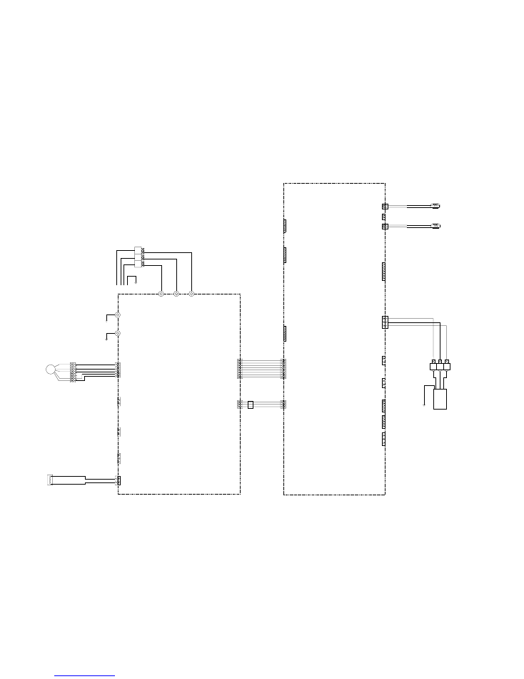
INDOOR UNIT
POWER SUPPLY PCB ASSEMBLY
K06AL-0605HSE-P0
UL1015 AWG14 YELLOW
UL1015 AWG14 BLUE
UL1007 AWG24 YELLOW
UL1007 AWG24 ORANGE
UL1007 AWG24 RED
UL1007 AWG24 BROWN
UL1015 AWG14 BLACK
UL1015 AWG14 WHITE
UL1015 AWG14 RED
WHITE / WHITE
WHITE
RED
BLACK
COMPRESSOR
C M
2
3
1
2
3
1
W305
B
W304
B
W303
B
W12
B
W13
B
W10
B
W11
B
W16
B
W17
B
W21
B
W22
B
N1
P
L1
L2
+
-
W9
B
W8
B
TM102
TM101
W3
B
W7
B
W2
B
W6
B
W1
B
EARTH
W200
B
SERIAL
CN800
B07B-XASK-1-A
WHITE
CN801
B07B-XAKK-1-A
BLACK
CN27
B06B-XARK-1-A
RED
CN30
179844-1
WHITE
CN37
B02B-XARK-1-A
RED
CN26
B02B-XAMK-1-A
GREEN
CN25
B02B-XAKK-1-A
BLACK
CN21
B02B-XH-AM-Y
YELLOW
CN22
B2B-XH-AM-R
RED
CN23
B02B-XAEK-1-A
BLUE
CN24
B2B-XH-AM
WHITE
UL1015 AWG14 WHITE
UL1015 AWG14 BLACK
UL1015 AWG20 WHITE
UL1015 AWG20 BLACK
UL1007 AWG24 BLACK
UL1007 AWG24 BROWN
UL1007 AWG24 RED
UL1015
AWG16
GREEN
UL1015
AWG20
BLACK
UL1015
AWG20
BLACK
UL1015
AWG20
WHITE
UL1015
AWG20
RED
UL1015
AWG12
WHITE
UL1015
AWG12
BLACK
UL1015
AWG12
BLACK
2
(N)
1
3
L
N
F202
FSL 250 10 ( EM )
( 250V 10A )
F201
TLC 25A - 250V, B
( 250V 25A )
YELLOW
WHITE
BLACK
RED
BROWN
YELLOW
WHITE
BLACK
RED
BROWN
YELLOW
BLUE
BROWN
RED
WHITE
ORANGE
1
2
3
4
5
6
7
1
2
3
4
5
6
1
2
3
4
5
6
7
1
3
1
2
1
2
3
1
2
1
2
1
2
1
2
1
2
1
2
BLACK
BLACK
RED
RED
BROWN
BROWN
BLACK
BROWN
BROWN
BLACK
BLACK
BLACK
BLACK
BLACK
BLUE
BLUE
F M
F M
M
DC FAN MOTOR 1
DC FAN MOTOR 2
EXPANSION VALVE
4-WAY VALVE
PRESSURE SWITCH
COMPRESSOR TEMP. TH.
HEAT SINK TEMP. TH.
DISCHARGE TEMP. TH.
PIPE TEMP. TH.
OUTDOOR TEMP. TH.
PIPE ( MID ) TEMP. TH.
INDOOR UNIT
POWER SOURCE
230V
50Hz
1
3
4
1
3
1
2
3
4
5
6
1
3
4
5
1
2
3
4
5
6
7
8
9
10
5V
GND
TAUX
TTXD
TRXD
TMODE
TAUX3
TCK
/ TRES
/ TICS
UL1015
AWG14
BROWN
UL1015
AWG14
BROWN
UL1015
AWG14
RED
UL1015
AWG14
BLACK
UL1015
AWG20
ORANGE
UL1015
AWG20
ORANGE
CHOKE COIL
EMI FILTER 3
TFC-25-15-12A
2T
ZPR0YCE400A300
CN1
03 XA / 172520
1007 L=180
WHITE
CT
CN34
B2P3-VH-B-Y
YELLOW
AC VOLT I N
CN407
06 PH / 172520
1007 L=480
WHITE
ACTPM CONTROL
CN601
B10B-PASK-1
WHITE
MAIN FLASH
CN1
B3B-XASK-1-A
WHITE
CT OUT
03 VH / SIN
1015 L=250
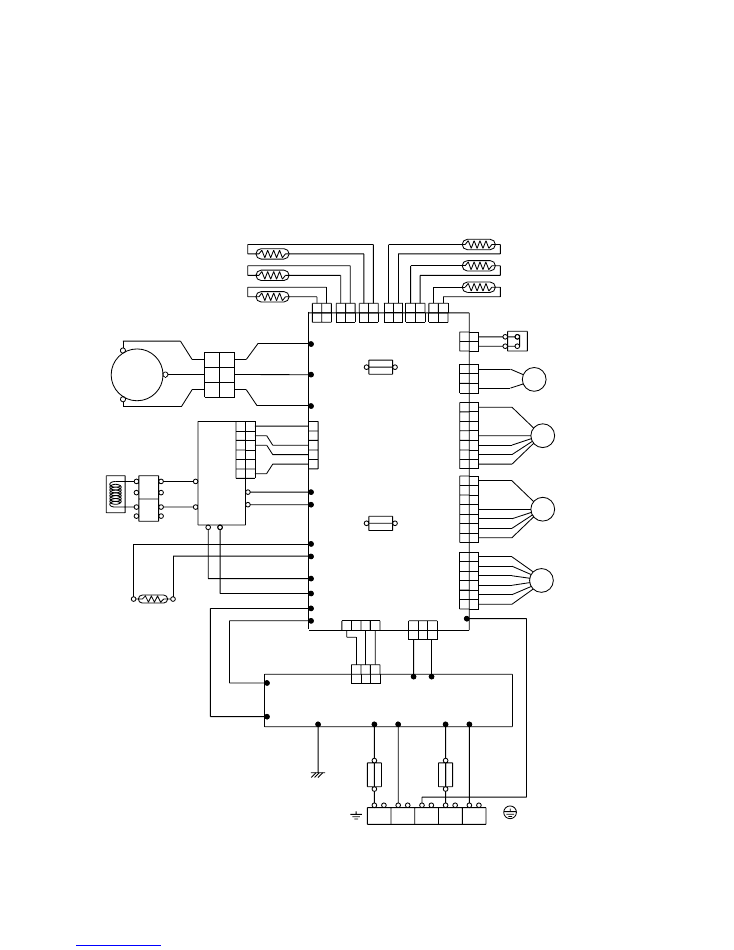
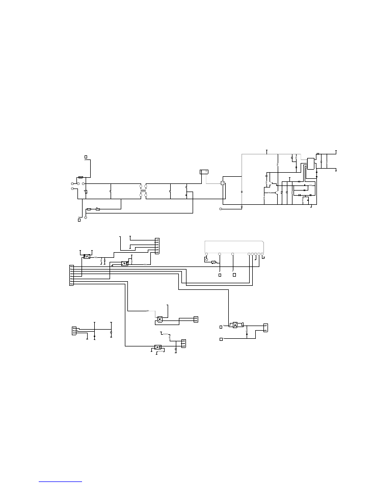
POWER SUPPLY PCB ASSY
K04BA-0401HUE-P0
CONTROLLER PCB ASSY
AOYA36LATL : K06DZ-0601HUE-C1
AOYA45LATL : K06DZ-0600HUE-C1
ACTPM
L=0.3MH
30A
SACT32010F1
EMI FILTER 2
TFC-25-15-12A
2T
EMI FILTER 1
TFC-25-15-12A
1T
2007.02.07
10
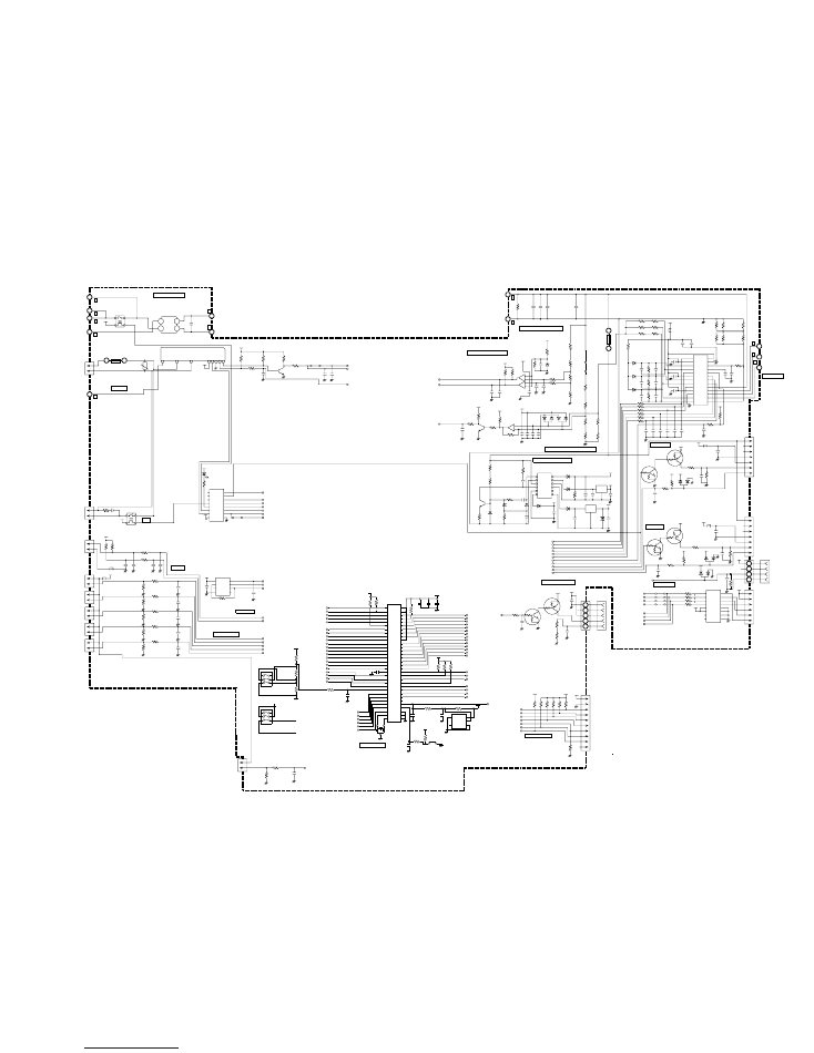
INVERTER ASSEMBLY
AOYA36LATL : EZ-00603HUE
AOYA45LATL : EZ-00604HUE
OUTDOOR PCB CIRCUIT DIAGRAM
B
B
C115
0.1
<HCP>
W16
RED
W17
BLACK
+
-
D101
D25XB60
12V
K101 DW12D1
B
B
B
B
B
L202
BL02Rn1
L201
BL02Rn1
5V
5V
CR5
RE1202
K17 G5NB-1A
12V
4WV
PR-SW
3
1
2
4
4
1
2
3
2
3
4
1
18
14
10
5 4 3 2 1
6
7
5 4 3 2 1
8
5V
12V
HY I C1
HU2001
VA103
470V
<TNR>
F4
T 5A
250V
PFC5000
-0702
FH1
PFC5000
-0702
FH2
3
1
1
2
1
2
1
2
1
2
1
2
1
2
1
2
CN23
B02B-XAEK-1-A
OUTDOOR TEMP. TH.
PIPE TEMP. TH.
CN22
B2B-XH-AM
RED
DISCHARGE TEMP. TH.
CN21
B2B-XH-AM
YELLOW
HEAT SINK TEMP. TH.
CN25
B02B-XAKK-1-A
BLACK
COMPRESSOR TEMP. TH.
CN26
B02B-XAMK-1-A
GREEN
PRESSURE SWITCH
CN37
B02B-XARK-1-A
RED
4-WAY VALVE
CN30
179844-1
WHITE
AC VOLT I N
CN34
B2P3-VH-B-Y
YELLOW
SERIAL
W200
RED
W11
WHITE
W10
BLACK
W21
ORANGE
W22
ORANGE
R98
4.75K 1%
<1/10W>
R100
13K
<1/10W>
R63
13K
<1/10W>
R65
4.75K 1%
<1/10W>
R67
38.3K 1%
<1/10W>
R101
10K
<1/10W>
R99
10K
<1/10W>
R62
10K
<1/10W>
R64
10K
<1/10W>
R66
10K
<1/10W>
C61
1.0
<F>
C60
1.0
<F>
C37
1.0
<F>
C38
1.0
<F>
C39
1.0
<F>
0.01 <F> x 2
C
73
C
72
C
70
C
71
0.
1
<F
>
x
2
1.0K <1/10W> x 2
R92
R93
2.2K
<1/10W>
x 2
R
91
R
90
C78
0.1
<F>
R68 4.75K
<1/10W>
1%
R35
10K
<1/10W>
P-AN-TT2
1
2
CN24
B2B-XH-AM
PIPE ( MID ) TH.
6
3
2
1
5
7
4
8 VCC
DO
NC
GND
CS
SK
D I
NC
I C201
BR93L56RF-WE2
R206
10K
<1/10W>
C91
0.1
<F>
5V
C56
1.0K
<1/10W>
P-S I
P-S I1
P-POWER
JM156
C
18
0
C
53
0.
02
2
<F
>
x
2
Q51
2SC2412K
<BQ>
R52
1.0K
<1/10W>
R56 27K
<1/10W>
R51 27K
<1/10W>
R55
1.0K
<1/10W>
R
50
1
0K
<1
/1
0W
>
5V
C51
0.022
<F>
1
2
3
1C
2C
3C
4C
5C
6C
7C
COM
1B
2B
3B
4B
5B
6B
7B
E 8
7
6
5
4
3
2
1
16
15
14
13
12
11
10
9
JM157
I C3
uLN2003A
D153, D152,
D151, D150
SLR-332VR
<RED> x 4
12V
D28
SLR-332VR
<RED>
R43 2.2K
<1/4W>
P-FM1SEL
P-V2
P-4WV-AC
P-LED
P-PR
P-SO1
P-SO
P-E2PCS1
P-E3PSK1
P-E2PD I 1
P-SWPRS1
P-SWPRS2
P-CMPTH
P-AN-HT
P-AN-TD
P-AN-TT
P-AN-TA
P-AFE
P-AFDC
P-CP-POS
P-U
P-V
P-W
P-X
P-Y
P-Z
P-TRIP
P-FM1POW
FM1FDB
P-FM2POW
FM2FDB
P-AN-CT
P-EPV-A
P-EPV-B
P-EPV-C
P-EPV-D
P-EPV1-A
P-EPV1-B
P-EPV1-C
P-EPV1-D
TAUX-1
TTXD-1
TRXD-1
TMODE-1
TAUX3-1
TCK-1
RSTX-1
P-AFS
5V
C95
100P
<CH>
R114
27K
<1/10W>
R113
1.0K
<1/10W>
2
1
3
R103
4.7K
<1/10W>
15V
15V
Q91
2SC2412K <BQ>
R102
22K
<1/10W>
I C11-1
uPC393
-
+
1
3
2
R115 1M
<1/10W>
C90
4.7/50V <PS>
+
C88
0.1
<F>
C89
470P
<B>
C87
330P
<B>
R108
2.87K
<1/10W>
1%
D81, D82
DAN217U x 2
3
3
2
1
2
1
7
1
2
3
6
5
-
-
+
+
+
5V
C35, C26
0.01 <F>
x 2
R407, R403
10K <1/10W>
x 2
SERIAL
MAIN CURRENT
VOLTAGE LOCK OUT
ACTPM CONTROL
18V
18V
A
C415
0.01
<F>
A
A
C416
1000P
<B>
Q401
DTC124EUA
A
A
R411
22K
<1/10W>
2
1
3
2
3
1
Q403
DTA143
R437,
R438
270 <1/10W>
1% x 2
C413
0.01
<F>
5V
5V
5V
R605
22K
<1/10W>
10K <1/10W> x 5
R
60
4
R
21
R
60
3
R
60
2
R
60
1
FLASH-MAIN
R20
10K
<1/10W>
1
10
9
8
7
6
5
4
3
2
1
5
4
3
2
CN407
06 PH / 172520
1007 L=480
WHITE
ACTPM
CONTROL
TAUX
TRXD
TMODE
TAUX3
TCK
/ TRES
/ TICS
TTXD
CN601
B10B-PASK-1
WHITE
MAIN-FLASH
THERMISTOR
EEPROM
1
6
5
4
3
2
1
4
3
2
1
7
6
5
4
3
2
1
7
6
5
4
3
2
W305
RED
W304
WHITE
W303
BLACK
INVERTER
B
B
B
CN800
B07B-XASK-1-A
WHITE
DC FAN
MOTOR-1
MOTOR-2
CN801
B07B-XAKK-1-A
BLACK
DC FAN
5V
CN1
03 XA / 172520
1007 L=180
WHITE
CT
CN27
B06B-XARK-1-A
RED
EXPANSION VALVE-A
12V
I C4
TD62064
I 1
I 2
I 3
I 4
COM1
COM2
NC1
NC2
O1
O2
O3
O4
GND1
GND2
GND3
GND4
15
10
8
1
14
11
6
3
13
12
5
4
16
9
7
2
12V
JM152
JM153
JM154
JM155
1.5K <1/10W> x 4
R97
R96
R95
R94
C29
0.1
<F>
5V
D61
DAN217U
1
2
3
3
1
2
D804
DAN217U
5V
5V
15V
R807
10K
<1/10W>
R808
1.0K
<1/10W>
C804
0.01
<F>
Q802
DTC143EUA
DC FAN-2
EE-VALVE
Q803
DTA143
R805
1.0K
<1/2W>
2
1
3 2
3
1
R806 560
<1/4W>
+
C803 <PJ>
100/16V
C805
0.1
<F>
L801
BL02Rn1
15V
C801
0.01
<F>
R804
1.0K
<1/10W>
D803
DAN217U
5V
5V
15V
DC FAN-2
1
2
3
2
1
3
Q800
DTC143
EUA
Q801
DTA143
R803
10K
<1/10W>
2
3
1
+
C800
100/
16V
<PJ>
R801
1.0K
<1/2W>
15V
L800
BL02Rn1 C802
0.1
<F>
R802
560
<1/4W>
C
31
1
C
31
2
C
31
3
C
31
4
C
31
5
C
31
6
1000P <B> x 6
C33
0.01
<F>
5V
R40 1.0K
<1/10W>
R33 10K
<1/10W>
I C310
PS21267-AP
13
12
11
10
9
8
7
6
5
4
3
2
1
26
25
24
23
22
21
20
19
18
17
16
15
14
UP
VP I
VUFB
VUFS
VP
VP I
VVFB
VVFS
WP
VP I
VPC
VWFB
VWFS
VN I
VNC
C IN
CFO
FO
UN
VN
WN
P
U
V
W
N
+
C328
2200P
<B>
R302 1.0K
<1/10W>
C327
0.022 <F>
0.1 <F> x 3
C324
C325
C326
15V
R370, R371, R374
R375, R376, R379
0.018 <2W> x 6
C333
47/
35V
C332
0.1
<F>
L3
00
BL
02
R
n1
R110
R88
R86
R89
R112
R111
195K <RN-1/2W> x 6
SW POWER SUPPLY
COMP POSITION DETECT
T1
JPZ-200
12V
5V
SMOOTHING CIRCUIT
15V
B
B
W12
W13
YELLOW
BLUE
R201
220K
<2W>
660/450WV x 3
C
20
1
C
20
2
+
C
20
3
+
+
C116
0.1
<HCP>
F2
T 3.15A
250V
FH3
PFC5000
-0702
FH4
PFC5000
-0702
I C400-2
uPC393
I C400-1
uPC393
15V
R402
2.2K
<1/4W>
D402
RD3.3ES
<B2>
R408
6.65K
<1/10W>
1%
C409
10/
25V
<PS>
R435, R441
1.0K <1/10W>
x 2
C411
0.01
<F>
C414
0.01
<F>
C412
0.1
<F>
A
+
+
C418
10/
35V
<PS>
18V
15V
+
D100
D1FL20U
C7
220/
35V
C6
100/
16V
<PS>
+
I C8
TA7805
+ +
1
2
3
I
G
O
I
G
O
2
1
3
I C407 uPC24M18
D
11
0
ZP
10
27
C406
220/
50V
<PJ>
R5
10K
<1/10W>
C4
470/
25V
<PJ>
C5
220/
16V
<PJ>
D1FL20U
x 3
D8
D7
D401
16
15
13
12
10
9
8
7
6
3
2
1
100K <2W>
x 2
R6
R1
Q1
2SC5354
R140 1.2
<1/2W>
D
1
D
1F
L2
0U
3
2
1
D
10
R
D
5.
6E
S
<B
2>
R4 330
<1/4W>
C3
100/16V
<PJ>+
D1
D1FL20U
C2 0.047
<ECQB>
R3 100
<1W>
R2 1.0K
<RS-3W>
C1
220P
<BN>
R
10
7
6
80
<1
/1
0W
>
1
%
R
87
2
.9
4K
<1
/1
0W
>
1
%
R
10
5
2
.9
4K
<1
/1
0W
>
1
%
R
10
6
R
10
4
19
5K
<
R
N
-1
/2
W
>
1%
x
2
R
40
1
2.
94
K
<1
/1
0W
>
1
%
R
40
6
2.
87
K
<1
/1
0W
>
1
%
18
0K
<
R
N
-1
/2
W
>
1%
x
2
R
40
0
R
44
0
L100
R
36
0
3
9
<1
/2
W
>
D
30
1
D
30
2
D
30
3
U
1J
U
44
x
3
47
/3
5V
<P
J>
x
3
33
0k
<1
/1
0w
>
x
3
0.
1
<F
>
x
3
C
32
2
C
32
1
C
32
3
C
30
3
C
30
5
C
30
4
+
+
+
R
36
2
R
36
1
R
36
3
1.0K
<1/10W>
x 6 R340
R341
R342
R343
R344
R345
1M
<1/10W>
R34
1.0K
<1/10W>
C77
0.1
<F>
P-AN-TT2
P-AN-HT
P-CMPTH
P-AN-TT
P-AN-TA
P-AN-TD
5V
R16
2.2K
<1/10W>
R17
1.8K
<1/10W>
R18
1.0K
<1/10W>
SW1
DSS803
6
5
4
3
2
1
I C1
MB90462
5V
R11, R195
10K <1/10W> x 2
C40 0.1
<F>
17
16
2
35
3
59
58
60
21
34
47
27
28
29
30
31
32
33
57
41
42
43
44
10
9
8
7
5
6
4
22
23
2
1
3
49
24
13
48
19
1
61
62
63
64
20
18
15
14
55
54
53
52
51
50
46
45
12
39
38
37
36
40
26
25
11
56
U
X
V
Y
W
Z
P63
P62
P46
P12
P50
P37
P36
P40
MD2
P11
P26
P02
P03
P04
P05
P06
P07
P10
C
P20
P21
P22
P23
P57
P56
P55
P54
P52
P53
P51
X0
X1
VCC
AVCC
P00
P01
P17
P13
P14
P15
P16
AVR
P24
P25
P30
P31
P32
P33
P34
P35
P60
P61
MD0
MD1
P44
P43
P42
P41
P45
RSTX
P27
AGND
GND
GND
X1
8.00MHz
<EFO>
C79
0.1
<F>
RSTX-1
2
1
5
4
3
NC
SUB VCC
VOUT
GND
C17
0.01
<F>
R36
1.0K
<1/10W>
R72 1.0K
<1/10W>
5V
C16
4.7/
50V
<PS>
+
R158
10K
<1/10W>
SW2
KSM0632B
5V
R73 82K
<1/10W>
I C6
BD4742G
R126 - R128
10K <1/10W> x 3
5V
R608 10K <1/10W>
C20
4.7/
50V
<PS>
+
5V
0.1 <F> x 2
C
19
C
18
FM2FDB
SUB-CLK
P-FM2POW
P-POWER
P-AN-CT
P-FM1POW
TTXD-1
TAUX3-1
P-AFS
P-CP-POS
P-S I
P-SO
P-PR
P-LED
P-4WV-AC
P-V2
P-TRIP
P-EPV-A
P-EPV-B
P-EPV-C
P-EPV-D
TAUX-1
P-E2PCS1
P-FM1SEL
FM1FDB
P-E2PD I1
P-E2PSK1
P-AFDC
P-AFE
P-U
P-X
P-V
P-Y
P-W
P-Z
SUB-FWD
SUB-BKWD
TMODE-1
P-SWPRS2
P-SWPRS1
TCK-1
TRXD-1
MICOM-MAIN
2007.02.07
11
CONTROLLER PCB ASSEMBLY
AOYA36LATL : K06DZ-0601HUE-C1
AOYA45LATL : K06DZ-0600HUE-C1
SW1
DSS803
6
5
4
3
2
1
AOYA36LATL
AOYA45LATL
5V
TM101
BLACK
TM102
WHITE
B
B
C111
2.2
<LE>
L4
RCH3818-022PF07
C107
3.3
<LE>
TM100
L2
N200500K1D7C
CT1
CT-1B
5V
D60
DAN217U
C64
0.1
<F>
R68 22K
<1/10W>
C65
0.1
<F>
VR1
KVSF687
AC202
+
R61 3.74K
<1/10W>
(1%)
C60
220/16V
<PJ>
R60 680
<1/10W>
(1%)
SA100
RA-302M
C106
1.0
<LE>
C104
0.033
<YE>
C105
0.033
<YE>
C101
1.0
<LE>
VA101
470V
<TNR>
VA102
470V
<TNR>
B
B
B
B
B
B
B
BLACK
WHITE
TO INDOOR UNIT
POWER SOURCE
230V
50Hz
EARTH
AC VOLT OUT
W2
W6
BLACK
WHITE
W7
GREEN
W3
W8
BLACK
WHITE
W9
W1
L1
RCH3818-022PF07
CN1
B03B-XASK-1-A
WHITE
CT OUT
1
2
3
2007.02.07
12
OUTDOOR UNIT
POWER SUPPLY PCB ASSEMBLY
K04BA-0401HUE-P0
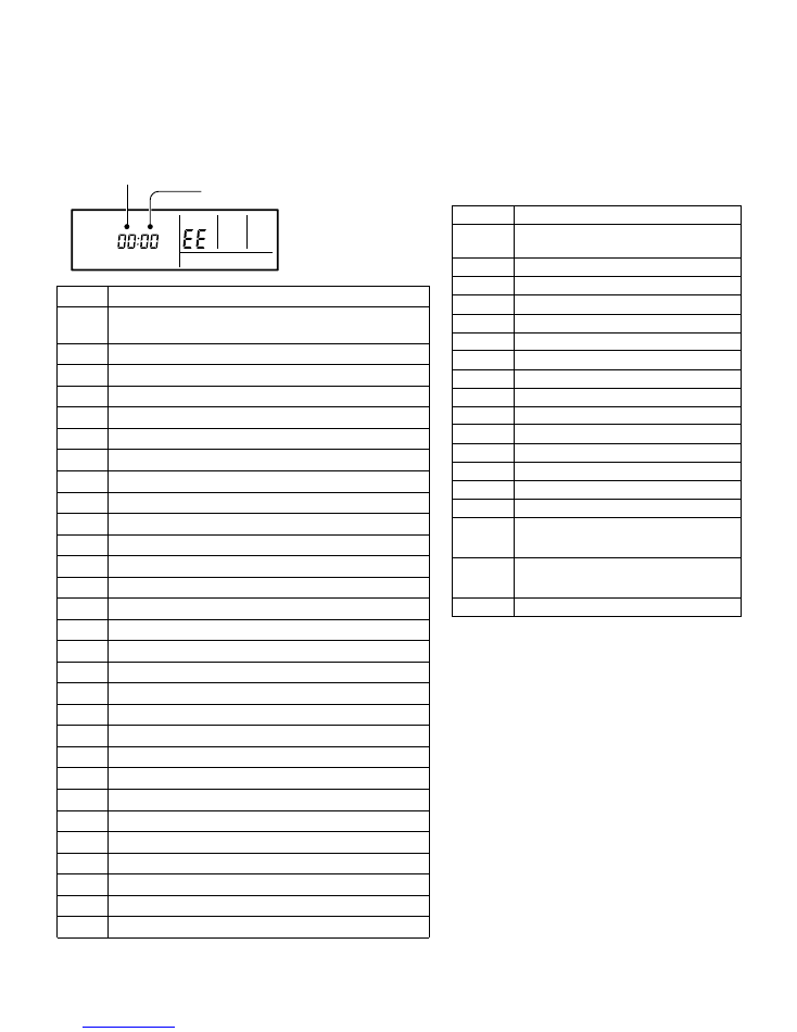
Troubleshooting at the remote control LCD
This is possible only on the wired remote control.
If an error occurs, the following display will be shown.
("EE" will appear in the set room temperature display.)
Unit number
Error code
SU MO TU WE TH FR SA
Code
Error contents
Indoor signal error
Wired remote controller abnormal
Indoor room temperature sensor error
Indoor heat exchanger temperature sensor (middle) error
Indoor heat exchanger temperature sensor (inlet) error
Float switch operated
Outdoor discharge pipe temperature sensor error
Outdoor heat exchanger temperature sensor (outlet) error
Outdoor temperature sensor error
Compressor temperature sensor error
2-way valve temperature sensor error
3-way valve temperature sensor error
Outdoor heat exchanger temperature sensor (middle) error
Indoor manual auto switch abnormal
Power supply frequency detection error
IPM protection
CT error
Compressor location error
Outdoor fan error
Connected indoor unit abnormal
Outdoor unit computer communication error
Indoor fan abnormal
Discharge temperature error
Exessive high pressure protection on cooling
4-way valve abnormal
Pressure switch abnormal
Compressor temperature error
Active filter abnormal
PFC circuit error
01 13
26 27
00
02
04
28
09
0C
06
0A
15
1d
1E
29
20
2A
17
18
1A
1b
1F
1c
12
0F
24
2c
16
2b
19
25
If "CO" appears in the unit number display, there is a remote control
error. Refer to the installation instruction sheet included with the
remote control.
2007.03.01
13
ERROR CONTENTS
REMOTE CONTROL UNIT
Make a TEST RUN in accordance with the
installation instruction sheet for the indoor unit.
OUTDOOR UNIT LEDS
When a malfunction occurs in the outdoor unit,
the LED on the circuit board lights to indicate the error.
Refer to the following table for the description of each
error according to the LED.
Error contents
Communication error
(Indoor unit - Outdoor unit)
Discharg pipe temperature sensor
Outdoor heat exchanger temperature (outlet) sensor
Outdoor heat exchanger temperature (mid) sensor
Outdoor temperature sensor
Compressor temperature sensor
Heat sink temperature sensor
Pressure switch abnormal
IPM error
Compressor rotor position cannot detect
Compressor cannot operate
Outdoor fan abnormal (upper fan)
Outdoor fan abnormal (lower fan)
Pump down operation
No error
LED
1 flash
2 flash
3 flash
4 flash
5 flash
Discharge pipe temperature abnormal
6 flash
7 flash
8 flash
9 flash
Compressor temperature abnormal
10 flash
12 flash
13 flash
14 flash
15 flash
16 flash
1 sec. on/
1 sec. off
repeat
Protect operation
5 sec. on/
1 sec. off
repeat
off
2007.03.01
14
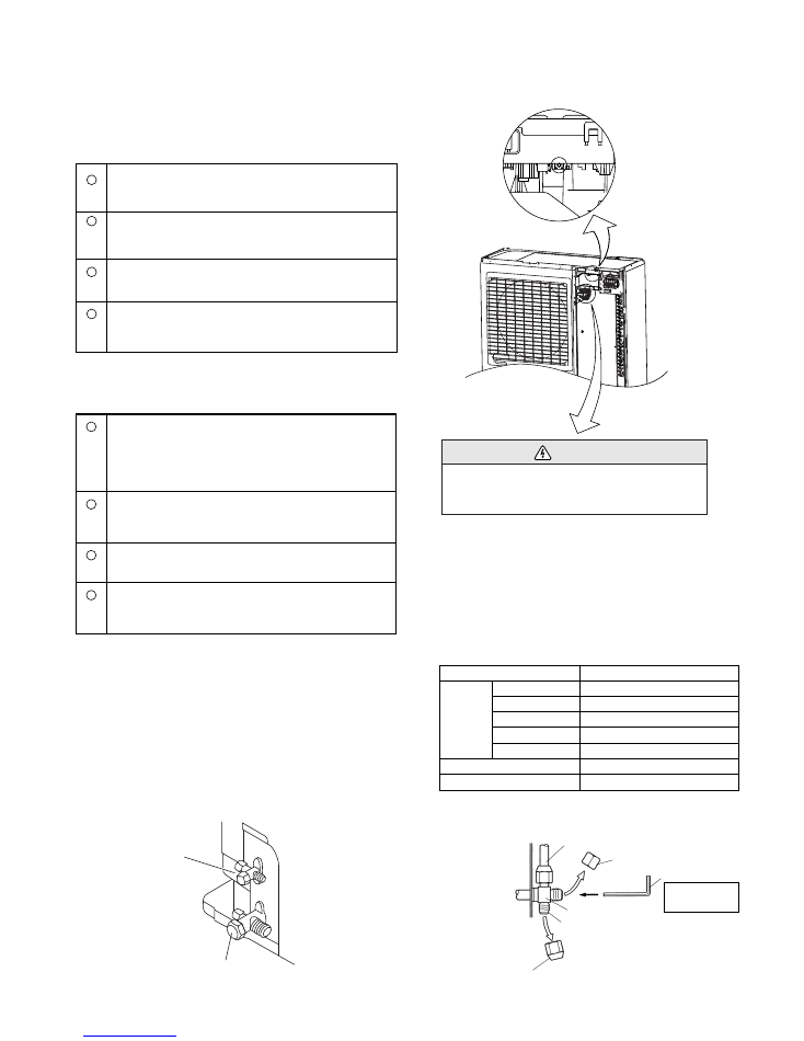
SPECIAL INSTALLATION SETTING
PUMP DOWN (Refrigerant collecting operation)
1. When the product is stopped:
Perform the following procedures to collect the refrigerant
when moving the indoor unit or outdoor unit
1
2
3
4
Press the PUMP DOWN switch on the outdoor unit.
(The LED on the outdoor unit circuit board starts flashing.)
(1 sec. on / 1 sec. off repeated)
The pump down operation (cooling operation) begins
right away. After oparation starts, close the three-way
valve (liquid).
After 2 - 3 minutes, operation stops. Close the three-way
valve (gas) within one minute after operations stops.
The LED will go out three minutes after it stops.
Disconnect the power supply after confirming that the
LED has gone out.
*When the pump down operation is repeated, temporarily disconnect the
power supply after opening the closed valves (both liquid and gas).
Reconnect the power supply after 2 - 3 minutes and perform the pump
down operation.
*When the start of the operation after pump down operation has been
completed, temporarily disconnect the power supply after opening the
closed valves (both liquid and gas).
Reconnect the power supply after 2-3 minutes and be sure to perform a
test operation for cooling.
2. When the product is operating:
1
2
3
4
Press the PUMP DOWN switch on the outdoor unit.
The LED on the outdoor unit circuit board starts flashing
( 1 sec. on / 1 sec. off repeated), and operation stops.
At this point, recovery has not been completed, so do not
close the three-way valves. (liquid and gas)
The pump down operation (cooling operation) be-
gins after three minutes. Close the three-way valve
(liquid) after operation starts.
After 2 - 3 minutes, operation stops. Close the three-way
valve (gas) within one minute after operations stops.
The LED will go out three minutes after it stops. Dis-
connect the power supply after confirming that the LED
has gone out.
3-way valve
(Liquid)
3-way valve
(Gas)
DANGER
This part (Choke coil) generates high voltages.
Never touch this part.
PUMP DOWN SW (SW2)
20 to 25 N-m (200 to 250 kgf-cm)
20 to 25 N-m (200 to 250 kgf-cm)
25 to 30 N-m (250 to 300 kgf-cm)
30 to 35 N-m (300 to 350 kgf-cm)
35 to 40 N-m (350 to 400 kgf-cm)
6 to 7 N-m (60 to 70 kgf-cm)
Tightening torque
Connecting pipe
Blank cap
Hexagon wrench
3-way valve
Charging port
Cap
Outdoor unit
Use a 4 mm
hexagon wrench.
Blank
cap
6.35 mm (1/4 in.)
9.52 mm (3/8 in.)
12.70 mm (1/2 in.)
15.88 mm (5/8 in.)
19.05 mm (3/4 in.)
Spindle (Hexagon wrench)
10 to 12 N-m (100 to 120 kgf-cm)
Charging port cap
8
7
5
4
6
1
9
10
2
3
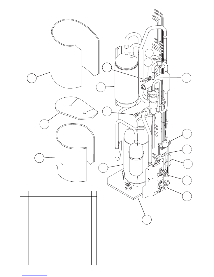
Insulation
Insulation
Control Box
Insulation
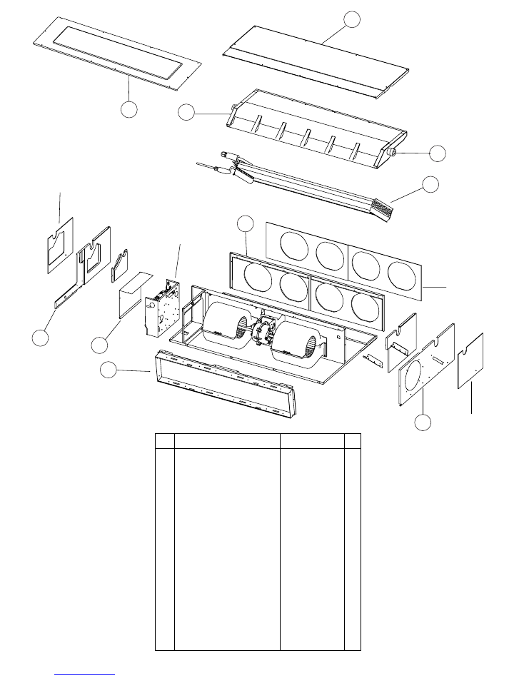
INDOOR UNIT
PARTS
2007.08.21
15
8 Control Cover A Sub Assy
9 Cabinet L Sub Assy
7 Cabinet R Sub Assy
1 Intake Cover Sub Assy
6 Outlet Panel Sub Assy
5 Evaporator Assy
3 Drain Pan Sub Assy
2 Main Panel Sub Assy
10 Intake Frame Assy
4 Drain Cap
-- Thermistor Spring A
Ref. Description
Part number
9374516018
9374509010
9374508020
9374512010
9374510016
-- Seal Panel Sub Assy
-- Bracket Pipe Sub Assy
-- Thermo Holder Pipe
-- Distributor Assy
9374515011
9374514014
313714262805
9371325385
-- Coupling Pipe Assy
9373038283
9372585047
9374513017
9374511013
9374216017
9356541007
313728262708
21
23
26
29
24
28
2007.08.21
INDOOR UNIT
16
26
Bracket Motor Assy
22
Sirocco Fan Assy
23
Base Sub Assy
24
Separate Wall Assy
29
Bracket (Eva) R
28
Fan Motor
--
Motor Band
Ref. Description
Part number
9374230013
9356531046
9374504015
21
Casing B
--
Bracket (Eva) L
Panel (Control Box)
27
Motor Mount
25
Casing A
9374234011
9374208012
9374210015
9378002012
9374233014
9374228010
9374207015
9602466016
9378031012
--
Cap (Power)
9352173011
22
25
27
--
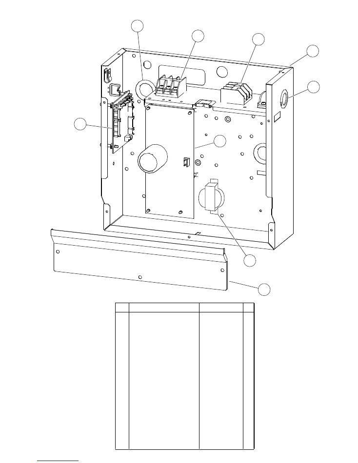
INDOOR UNIT
Control unit
43
45
44
48
49
42
41
47
2007.10.25
17
41
Controller PCB Assy (36)
41
Controller PCB Assy (45)
9707393125
43
Cap (Power)
9352173011
48
Control Box A
9374219018
49
Control Cover B
9374222018
44
One Touch Bush
9374407019
45
Terminal 3P
9703345012
46
Terminal 3P
9306489045
42
Power Supply PCB Assy
9707398069
47
Reactor Assy
9707457018
--
Room Thermistor
9703299025
--
Pipe Thermistor
9703297021
--
--
Remote Control
9372266199
--
--
Wire Assembly
9372714010
Ref. Description
Part number
--
Control Box B
9374220014
9707393118
46
1
6
7
5
2
3
4
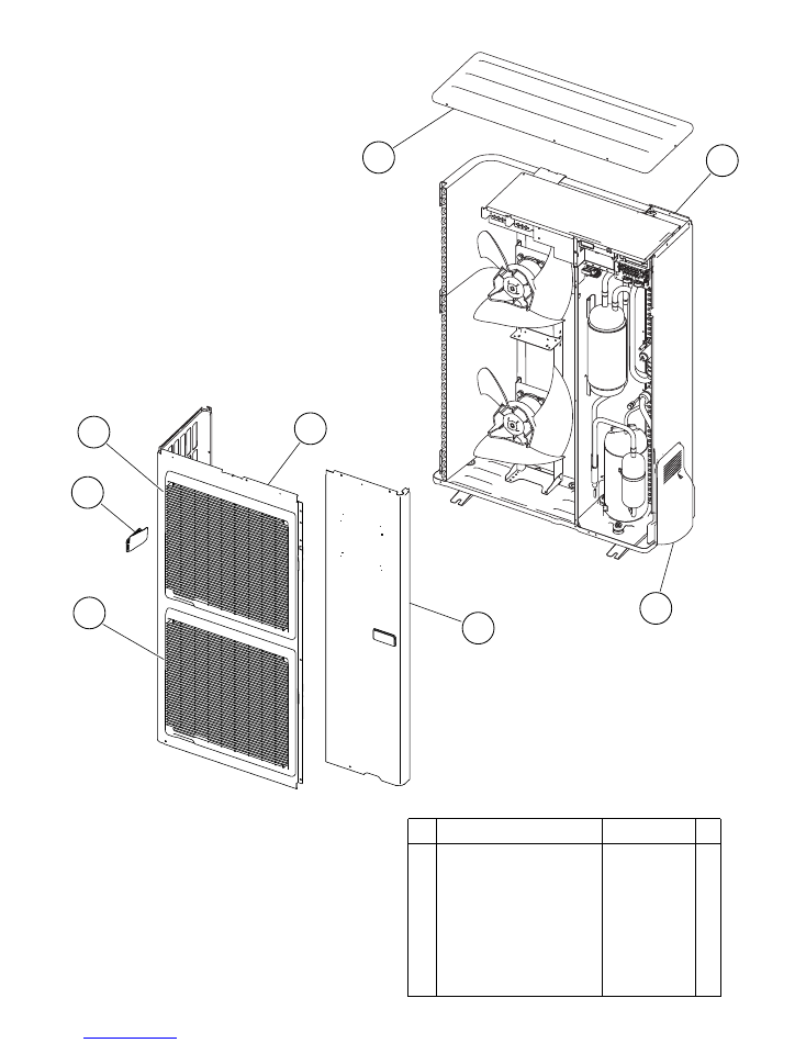
3
OUTDOOR UNIT
PARTS
2007.02.02
18
1 Top Panel Sub Assy
2 Front Panel
3 Fan Guard
4 Grip Side
5 Service Panel Sub Assy
6 Right Panel Sub Assy
7 Valve Cover
9374417025
9374094028
9374330010
9374173013
9374415069
9374416141
9374174010
-- Emblem Rear
9351355005
Description
Parts number
Ref.
13
12
11
10
9
15
14
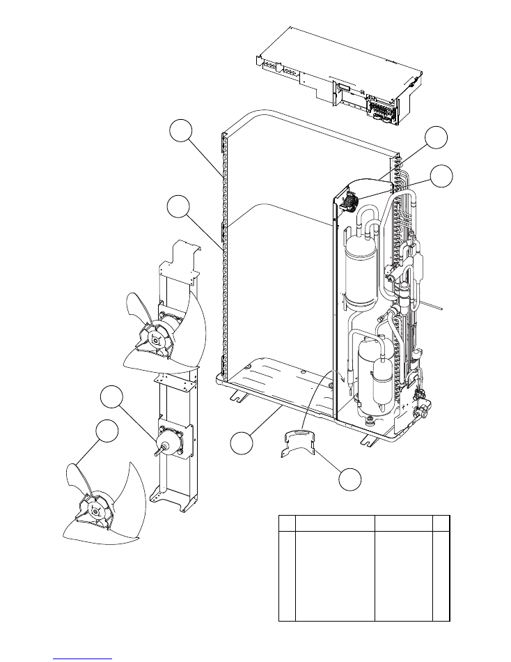
OUTDOOR UNIT
2007.03.101
19
9 Propeller Fan Assy
10 Motor DC Brushless
11 Condenser A Assy
12
Condenser B Assy
13 Sepa Wall
14 Cap Foot
15 Base Assy
9366378020
9601882015
9374433018
9374434015
9374629015
9374345014
9374166046
Description
Parts number
Ref.
16
16 Coil Choke
9703458019
OUTDOOR UNIT
2007.08.21
20
56
55
54
57
18
17
26
42
25
19
24
23
21
22
20
17 3-Way Valve Assy
18 3-Way Valve Assy
19 Compressor Assy
20 Accumulator Assy
21
Solenoid
22 Pressure Switch
23
4-Way Valve
24 Check Valve Assy
25 Coil (Expansion Valve)
26 Strainer Assy
55 Compressor Cover B
56
Compressor Cover C
57 Compressor Cover D
42 Expansion Valve Assy
54 Compressor Cover A
9377958013
9377959010
9378035010
9375250034
9900165055
9900186012
9970035029
9374274017
9900197025
9372524039
9374431106
9372067086
9375382025
9370947175
9374430109
Description
Parts number
Ref.
58 Solenoid
9900165055
58

31
38
27
36
28
29
33
37
OUTDOOR UNIT
2009.01.07
21
(Connector : Black)
32
30
40
51
39
48
52
53
41
50
43
44
45
46
47
(Green)
(Blue)
(Red)
(Yellow)
(White)
(Connector
: Red)
47 Heatsink Thermistor
52 Fuse Holder (Large)
48 Wire (Pressure Switch)
50 Thermistor (Heat Exchanger)
9900311018
0501454012
51 Fuse Holder (Small)
0501456016
9367595051
9900403010
27 Inverter Box A
28 Inverter Box B
29 Inverter Box C
30 Inverter Box Duct
36 Posistor
37 Inverter PCB Assy (36)
38 Power PCB Assy
39 Clamp (Cord)
40
Terminal
41 Fuse (Small)
43 Thermistor (Dischage)
44 Thermistor (Heat Exchanger)
45 Thermistor (Out Temp)
46 Compressor Thermistor
31
Inverter Box Cover
32 Heat Sink B
33 ACTPM
9374603015
9374625017
9374605026
9374609017
9704265012
9707537024
37 Inverter PCB Assy (45)
9707537017
9705647022
9356857009
9900203023
0600086039
9704219084
9900374037
9900378035
9900156060
9374608010
9374607020
9707592016
Description
Parts number
Ref.
53
Fuse (Large)
0600086039
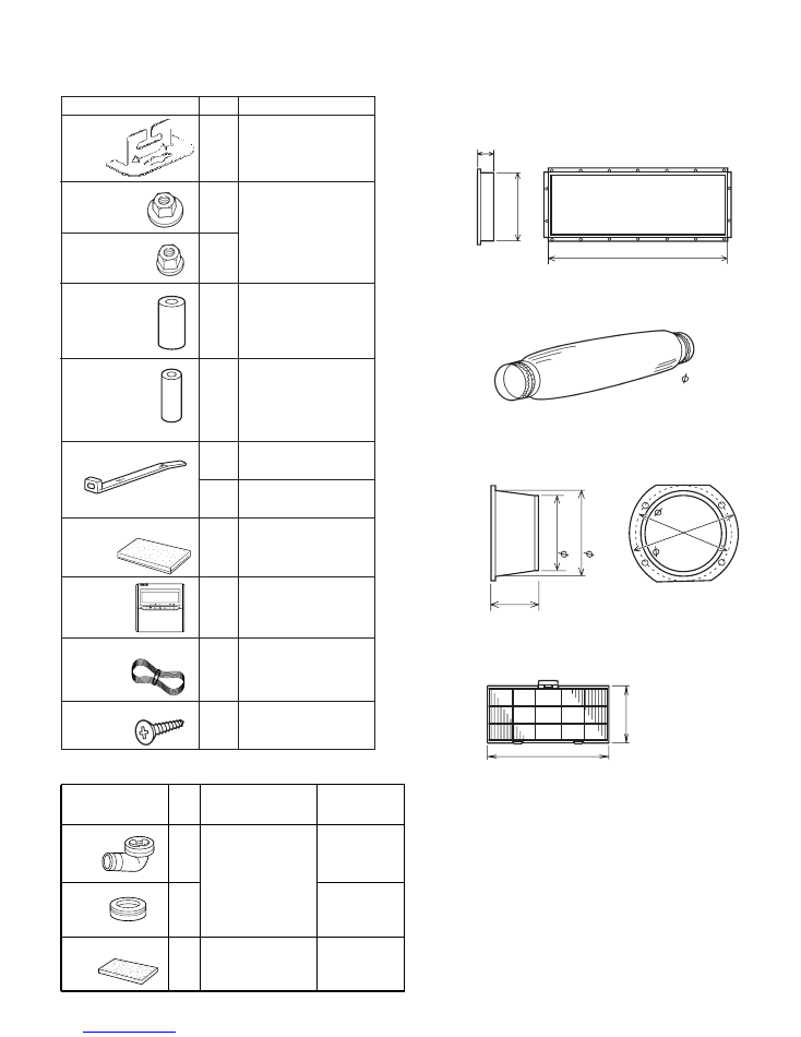
ACCESSORIES
INDOOR UNIT
Name and Shape
Hanger
Special nut A
(large flange)
Special nut B
(small flange)
Coupler heat
insulation (large)
Coupler heat
insulation (small)
Q'ty
4
4
4
1
1
Application
For suspending the indoor
unit from ceiling
For suspending the indoor
unit from ceiling
For indoor side pipe joint
(large pipe)
For indoor side pipe joint
(small pipe)
Binder
Drain hose insulation
1
(large)
1
(small)
1
For fixing the drain hose
For fixing the remote
controller cord
Insulates the drain hose
and vinyl hose
OPTIONAL PARTS
Square flange
Round flange
Model name : UTD-SF045T (P/N 9098180007)
Model name : UTD-RF204 (P/N 9093160004)
Flexible duct
Long-life filter
Model name : UTD-RD202 (P/N 9074165004)
Model name : UTD-LF25NA (P/N9079892004)
Remote sensor
Model name : UTD-RS100 (P/N9072619004)
40 mm
20
4
m
m
1065 mm
L 2 m
507 mm
23
9
m
m
2007.10.25
22
85 mm
19
5
m
m
20
5
m
m
225 m
m
235
mm
200 mm
Name and Shape Q'ty
Part No.
Application
Installation
(seal)
1
2
1
OUTDOOR UNIT
For outdoor unit
drain piping work
(May not be supplied,
depending on the
model)
For filling in a gap at
the entrance of
connection cords
Drain pipe
Drain cap
9303029015
313166024302
9374756018
Remote
controller
1
For air conditioner
operation
Remote controller cord
(*1)
1
For connecting the
remote controller
Tapping screw
(ø4 × 16)
2
For installing the
remote controller
External control set
Model name : UTD–ECS5A (P/N 9077359004)

0708G3260