Full Text Searchable PDF User Manual
SPLIT TYPE
AIR CONDITIONER
(50Hz)
DUCT
type
Models
Indoor unit
Outdoor unit
ARY30FUAN
ARY30UUAN
AOY30FNBWL
AOY30UNBWL
CONTENTS
SPECIFICATIONS . . . . . . . . . . . . . . . . . . . . . . . . .1
OUTLINE AND DIMENSIONS . . . . . . . . . . . . . 2
CIRCUIT DIAGRAM . . . . . . . . . . . . . . . . . . . . . .
4
REFRIGERANT SYSTEM DIAGRAM . . . . . . .
5
INDOOR PCB CIRCUIT DIAGRAM . . . . . . . . 7
OUTDOOR PCB CIRCUIT DIAGRAM . . . . . 9
DISASSEMBLY ILLUSTRATION . . . . . . . . . . .11
PARTS LIST . . . . . . . . . . . . . . . . . . . . . . . . . . . . 20
ACCESSORIES . . . . . . . . . . . . . . . . . . . . . . . . . 22
ERROR CONTENTS . . . . . . . . . . . . . . . . . . . . . 10

ADDITIONAL REFRIGERANT CHARGE (R410A)
Pipe Length
7.5 m (25 ft)
2,300 g (81.1 oz)
2,300 g (81.1 oz)
10.0 m (33 ft)
2,350 g (82.9 oz)
2,400 g (84.7 oz)
20.0 m (66 ft)
2,550 g (89.9 oz)
2,800 g (98.8 oz)
30.0 m (99 ft)
2,750 g (97.0 oz)
3,200 g (112.9 oz)
ADDITIONAL CHARGE
FULL CHARGE
AMOUNT
20 g / m (0.21 oz/ft)
40 g / m (0.43 oz/ft)
SPECIFICATIONS
TYPE
COOLING
COOLING & HEATING
INDOOR UNIT
ARY30FUAN
ARY30UUAN
OUTDOOR UNIT
AOY30FNBWL
AOY30UNBWL
COOLING CAPACITY
(kW)
(kW)
8.40
8.40
HEATING CAPACITY
----
9.50
POWER SOURCE
(V)
(Hz)
230
FREQUENCY
RUNNING
(A)
COOLING
14.0
14.0
CURRENT
HEATING
----
12.4
INPUT WATTS
(kW)
COOLING
2.99
2.99
HEATING
----
2.63
E.E.R.
(kW/kW)
COOLING
2.81
2.81
HEATING
----
3.61
MOISTURE REMOVAL
( /hr)
3.0
AIR CIRCULATION
(m
3
/hr)
1,400
ELECTRICAL DATA
FAN MOTOR
COMPRESSOR
Hermetic type, 2 poles, Induced by condenser, Rotary
5JS330DAE01
(V)
230
DISCRIMINATION
MFA-30PTT
INDOOR
HI-SPEED
( r.p.m. )
990
UNIT
MED-SPEED
( r.p.m. )
920
LO-SPEED
( r.p.m. )
850
OUTDOOR
DISCRIMINATION
MFB-30PTT
HI-SPEED
( r.p.m. )
780
UNIT
LO-SPEED
( r.p.m. )
400
WEIGHT
INDOOR UNIT
NET / GROSS
43 / 50
OUTDOOR UNIT
(kg)
NET / GROSS (kg)
68 / 74
69 / 75
50
DIMENSIONS
INDOOR UNIT
H x W x D
270 x 1,135 x 700
OUTDOOR UNIT
(mm)
H x W x D (mm)
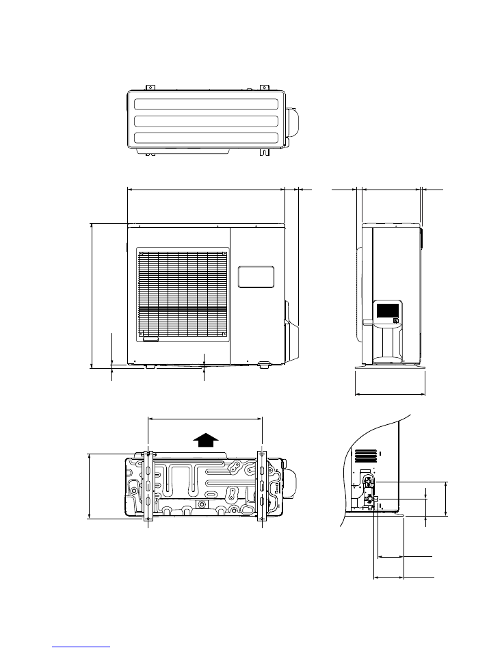
830 x 900 x 330
FAN NOISE
High
50 dB
50 dB
Med
48 dB
48 dB
Low
45 dB
45 dB
OUTDOOR UNIT
INDOOR UNIT
-
-
TYPE
DISCRIMINATION
POWER SOURCE
2005.04.27
1
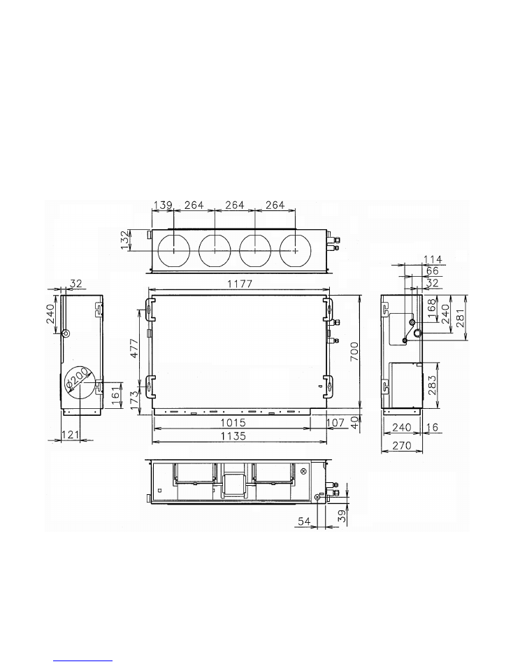
Unit : mm
DIMENSIONS
INDOOR UNIT
2005.04.11
2
400
300
31
77
900
83
0
21
9
12
37
0
19
6
147
170
99
650
Air Flow
2005.04.11
3
Unit : mm
OUTDOOR UNIT
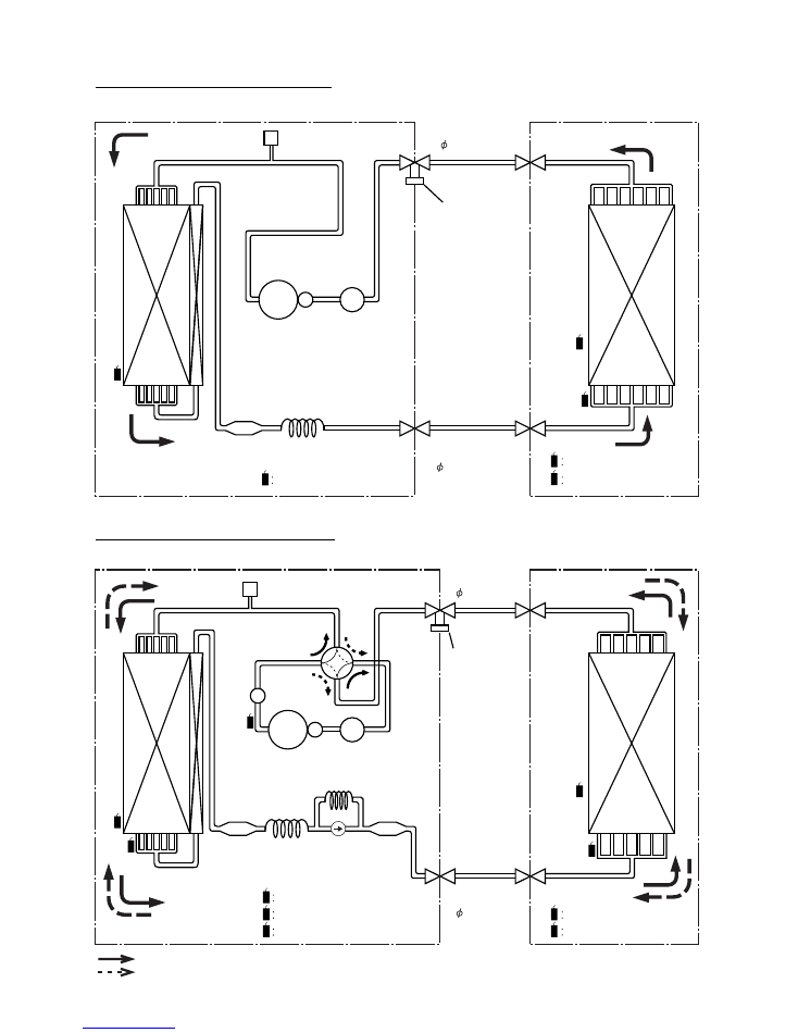
: COOL
: HEAT
M
UF
FL
ER
COMPRESSOR
ACCUMULATOR
STRAINER
THERMOSTAT (OUTDOOR TEMP.)
EV
AP
O
RA
TO
R
CO
ND
EN
SE
R
PRESSURE
CHECK VALVE
REFRIGERANT PIPE
15.88mm(5/8")
REFRIGERANT PIPE
9.52mm(3/8")
OUTDOOR UNIT
INDOOR UNIT
CHARGING
VALVE
4-WAY
VALVE
CAPILLARY
TUBE
Models : ARY30FUAN / AOY30FNBWL
Models : ARY30UUAN / AOY30UNBWL
THo
TH
R
TH
R
TH
PI
TH
PI
THo
THERMISTOR (PIPE TEMP.)
THERMISTOR (ROOM TEMP.)
TH
R
TH
PI
THERMISTOR (PIPE TEMP.)
THERMISTOR (ROOM TEMP.)
COMPRESSOR
ACCUMULATOR
STRAINER
STRAINER
THERMOSTAT (DISCHARGE TEMP.)
EV
AP
O
RA
TO
R
CO
ND
EN
SE
R
PRESSURE
CHECK VALVE
REFRIGERANT PIPE
15.88mm(5/8")
REFRIGERANT PIPE
9.52mm(3/8")
OUTDOOR UNIT
INDOOR UNIT
CHARGING
VALVE
CAPILLARY
TUBE
TH
D
TH
R
TH
PI
TH
O
TH
D
TH
PO
THERMOSTAT (OUTDOOR TEMP.)
TH
O
THERMOSTAT (PIPE TEMP.)
TH
PO
REFRIGERANT SYSTEM DIAGRAM
2005.04.11
4
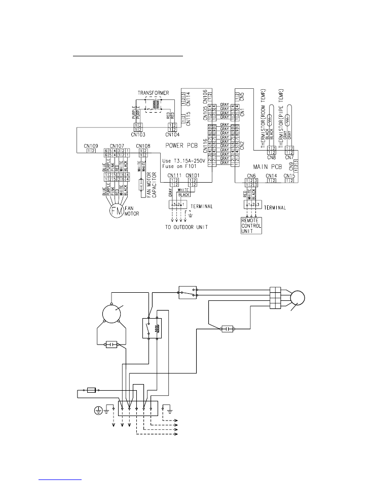
Models : ARY30FUAN / AOY30FNBWL
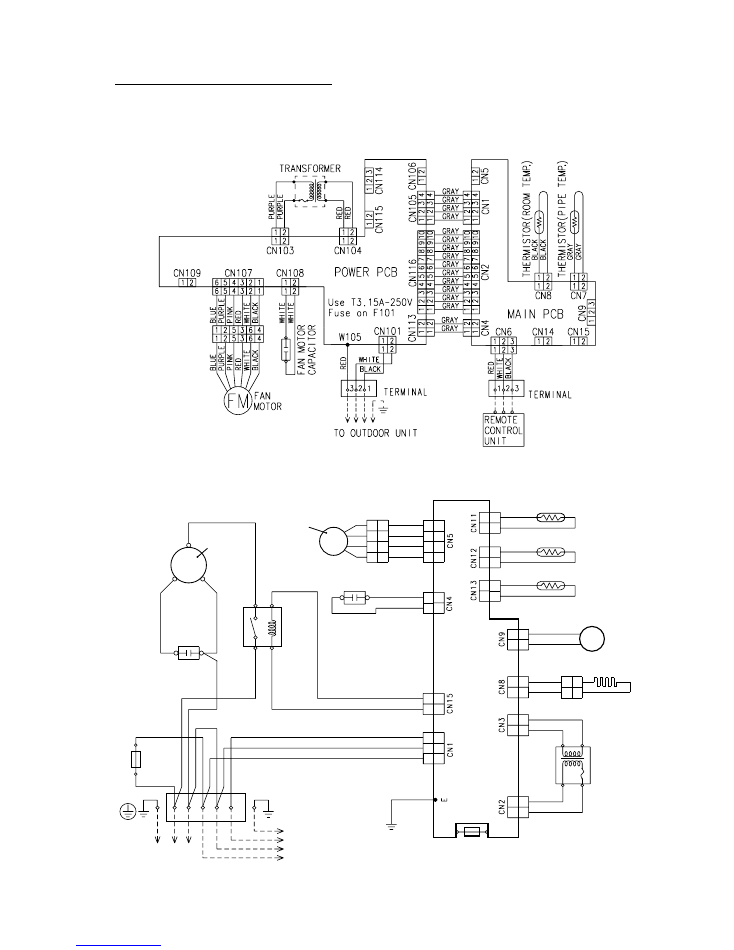
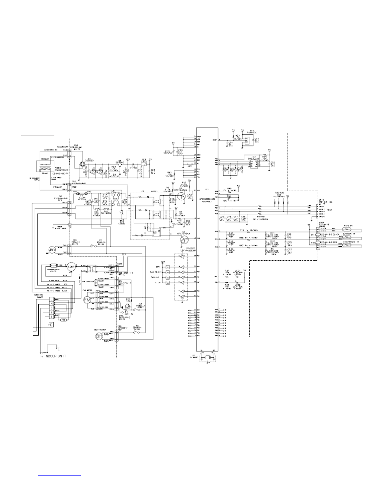
CIRCUIT DIAGRAM
C M
F M
THERMAL
PROTECTOR
TERMINAL
COMPRESSOR
INTERNAL
OVERLOAD
PROTECTOR
COMPRESSOR
CAPACITOR
FAN MOTOR
CAPACITOR
OUTDOOR
THERMOSTAT
FAN MOTOR
FUSE
TO INDDR
UNIT
TO POWER SUPPLY
RE
LA
Y
WHITE
WHITE
WHITE
BLACK
BLACK
BLACK
W
HI
TE
BL
AC
K
PURPLE
GRAY
BLUE
RED
W
HI
TE
RE
D
BR
O
W
N
BR
O
W
N
1
N
L
2 3
S
R
C
L
H
1
5
4
6
C
1
3
6
4
1
3
6
4
OUTDOOR UNIT
INDOOR UNIT
2005.04.27
5
C M
4WV
F M
PR
IN
TE
D
CI
RC
UI
T
BO
AR
D
THERMAL
PROTECTOR
TERMINAL
COMPRESSOR
INTERNAL
OVERLOAD
PROTECTOR
COMPRESSOR
CAPACITOR
FAN MOTOR
CAPACITOR
FAN MOTOR
FUSE
FUSE
TO INDDR
UNIT
TO POWER SUPPLY
RELAY
WHITE
WHITE
WHITE
YELLOW
YELLOW
BLACK
BLACK
BLACK
BLACK
BLACK
GRAY
GRAY
BLACK
BLACK
BLACK
BLACK
BLACK
RED
RED
W
HI
TE
BL
AC
K
GRAY
GRAY
BLUE
RED
RED
W
HI
TE
RE
D
RE
D
RE
D
BROWN
BROWN
1
N
L
2 3
S
R
1
5
4
6
C
1
3
6
4
1
3
6
4
4
3
2
1
7
5
3
1
2
1
2
1
2
1
2
1
2
1
2
1
2
1
2
1
1
3
2
1
1
3
2
1
2
1
2
1
2
1
2
1
3
1
2
1
2
1
2
1
2
1
3
3
5
1
OUTDOOR UNIT
INDOOR UNIT
THERMISTOR
(DISCHARGE TEMP.)
SOLENOID COIL
BELT HEATER
TRANSFORMER
THERMISTOR
(OUTDOOR TEMP.)
THERMISTOR
(PIPE TEMP.)
PURPLE
PURPLE
Models : ARY30UUAN / AOY30UNBWL
2005.04.28
6
9
8
7
6
5
4
3
2
1
10
11
12
13
14
15
16
5V
5V
R41 1.0K <1/10W>
5V
C40
0.01
<F>
C2
10/
25V
+
12V
1
2
3
4
5
6
7
8
7
10
2
3
4
5
1
2
3
4
5
1
2
1
2
1
5V
BLACK
BLACK
GRAY
GRAY
1
3
2
1
2
1
2
1
2
3
1
2
3
VCC
VOUT
GND
SUB
NC
5
4
3
1
2
5V
5V
C12
0.1
<F>
I C9
BD4742G
D1
DAN202K
C37
0.01
<F>
C11
0.1
<F>
X1
CSTS0500MG03-T
2
1
3
70
69
X1
X2
12
13
16
17
42
41
43
44
50
63
19
20
21
22
23
24
29
26
27
28
9
8
25
30
46
45
33
67
4
7
75
68
74
10
11
6
5
3
2
1
65
66
73
80
79
78
76
77
59
58
57
56
55
54
53
52
71
14
15
40
36
37
38
39
62
61
51
47
48
49
72
35
31
32
34
18
64
60
RESET
P03
P27
P56
P55
P54
R72
10K
<1/10W>
R80
10K
<1/10W>
R79 1.0K
<1/10W>
C10
0.1
<F>
5V
R39
10K
<1/10W>
C36
0.01
<F>
R40 1.0K
<1/10W>
5V
C13
0.1
<F>
5V
I C7
BR93LC46
R45 - R47
10K <1/10W> x 3
NC
R48 10K <1/10W>
P57
XT2
P35
P34
P33
P37
P00
P23
P24
P64
P60
P61
P62
P63
P01
I C
P120
P121
P127
P126
P125
P124
P123
P122
P14
P13
P12
P10
P11
P04
P05
P07
P15
P16
P17
P130
P131
P72
P20
VDD0
VDD1
AVRF0
AVRF1
AVSS
VSS0
VSS1
P31
P32
P53
P46
P70
P71
P51
P50
P47
P52
P45
P44
P43
P42
P41
P40
P02
P36
P30
P67
P66
P65
P21
P22
P25
P26
C27
0.1
<F>
C26
0.1
<F>
C25
0.1
<F>
C24
0.1
<F>
R21 - R24
1.0K <1/10W> x 4
5V
C28 - C31
0.01 <F> x 4
5V
14V
R33 - R36
1.0K <1/10W> x 4
10K <1/10W> x 4
R29
R30
R32
R31
BZ1
R37 1.0K
<1/10W>
R38 1.0K
<1/10W>
I C3 (1/7)
uPA2003GR
12
5
1
2
3
4
5
1
2
4
3
2
1
8
4
2
1
5 C
1
2
3
4
5
6
1
3
4
2
1
9
3
7
6
5
4
8
2
10
K104
SSR
I NT
1
2
3
4
3
2
1
3
1
2
2
3
1
O
I
G
O
I
G
2
1
3
2
1
4
2
1
3
2
1
1
2
4
3
1
2
4
3
1
2
3
4
1
2
2
1
1
2
5V
5V
C21 - C23
0.1 <F>
x 3
C17 - C20
0.1 <F> x 3
5V
+
C3
0.01
<F>
5V
C1
100/
6.3V
5V
5V
14V
PC103
TLP621
<GB>
14V
12V
5V
SW2
R15 - R17
10K <1/10W>
x 3
R18 - R20
1.0K <1/10W> x 3
SW1
14V
I C5 (7/7)
uPA2003GR
JM4
5V
14V
I C3 (3/7)
uPA2003GR
14V
D3
D1FS4A
D2
DA226U
12V
12V
14V
REMOTE CONTROL UNIT
TERMINAL BOARD
EARTH WIRE
3 2 1
U
L1
43
0
A
W
G
22
B
LA
C
K
U
L1
43
0
A
W
G
22
R
E
D
U
L1
43
0
A
W
G
22
W
H
IT
E
R43
R44
10K <1/10W> x 2
I C3 (1/7)
uPA2003GR
R71
10K
<1/10W>
R68
15.4K
<1/10W>
R69
28K
<1/10W>
R70
10K
<1/10W>
I C3 (1/7)
uPA2003GR
I C6-2
BA10393F
I C6-1
BA10393F
R67 390
<1/10W>
6
11
2
3
1
7
6
5
+
+
-
-
9
8
15
14
13
2
3
4
1
2
3
6
8
4
7
5
CS
SK
D I
NC
VCC
DO
NC
GND
R42 47
<1/10W>
C41
1000P
<R>
C39
0.01
<F>
R50 10K
<1/10W>
R49 10K
<1/10W>
R62 - R64
10K <1/10W> x 3
R57 - R59
1.0K <1/10W> x 3
C14
0.1
<F>
C15
0.1
<F>
C16
0.1
<F>
C8
0.1
<F>
C9
0.1
<F>
R60 1.0K
<1/10W>
R61 1.0K
<1/10W>
14V
R65
10K
<1/10W>
R66
49.9K
<1/10W>
5V
JM1
JM2
JM3
10K <1/10W> x 3
R3
R2
R1
R4 1.0K <1/10W>
R6 1.0K <1/10W>
R5 1.0K <1/10W>
CN8
B2B-XASK-1-A
WHITE
CN7
B2B-XAKK-1-A
BLACK
ROOM TEMPERATURE THERMISTOR
PIPE TEMPERATURE THERMISTOR
CN11
B5B-XASK-1-A
WHITE
LOUVER ( UP / DOWN )
CN12
B5B-XARK-1-A
RED
LOUVER ( RIGHT / LEFT )
CN13
B8B-XASK-1-A
WHITE
INDICATOR
CN6
B3B-XAKK-1-A
BLACK
CN14
B02B-PAMK-1
GREEN
FRESH AIR
HEATER
CN15
B02B-PA0K-1
ORANGE
CN9
B3B-XARK-1-A
RED
FLOAT SWITCH
FEED BACK
CN10
B3P-VH-B
WHITE
SW3
R25 - R28
10K <1/10W>
x 4
FAN CAPACITOR
10uF
440V
CN108
B2P3-VH-B-Y
YELLOW
CN3
B5P-SHF-1AA
WHITE
TEST
CN107
B6P11-VH-B
WHITE
CN109
B2P3-VH-B-E
BLUE
DRAIN PUMP
1
2
14V
CR101
120 / 0.2
K104
G5N-1A
K102
G5SB-14
DC12V
K103
G5SB-14
DC12V
K101
G5SB-14
DC12V
K108
G5N-1A
CR104
120 / 0.2
CN111
B2P3-VH-B
WHITE
1
2
CN101
B2P3-VH-B-C
BLACK
AC I N
MAGNETIC
RELAY
N
L
FH101
FH102
F101
3.15A
<BET>
VA101
470V
K110
G2R-1A
DC12V
14V
K108
K103
K101
K110
K102
1
9
3
7
6
5
4
8
2
10
UL1430 AWG26 GRAY
UL1430 AWG26 GRAY
UL1430 AWG26 GRAY
UL1430 AWG26 GRAY
UL1430 AWG26 GRAY
UL1430 AWG26 GRAY
UL1430 AWG26 GRAY
UL1430 AWG26 GRAY
UL1430 AWG26 GRAY
UL1430 AWG26 GRAY
RELAY DRIVE
CN116
B10B-PASK-1
WHITE
CN2
B10B-PASK-1
WHITE
5V
Q2
DTC124EKA
C33
0.01
<F>
C32
0.01
<F>
R78 390
<1/10W>
R77 390
<1/10W>
1
2
3
8
16
14
12
9
11
6
4
2
13
15
3
1
5
8
9
15
13
2
4
14
16
1
3
1
2
3
2
1
2
1
10
7
2
1
1
16
C35
0.01
<B>
R73
10K
<1/10W>
R74 1.0K <1/10W>
5V
R53
10K
<1/10W>
C38
0.01
<F>
R55
10K
<1/10W>
R56 1.0K <1/10W>
I C2 (1/7)
uPA2003GR
I C3 (1/7)
uPA2003GR
C34
0.01
<F>
R54 180
<1/10W>
14V
14V
Q1
DTA143
I C4 (4/7)
uPA2003GR
I C2 (6/7)
uPA2003GR
B Z
1
3
FAN
MOTOR
OUTDOOR UNIT
2(N)
JM101
JM102
5V
C113
0.01
<B>
R105 1.0K
<1/4W>
R106
10K
<1/4W>
D104
1SR139-600
R104 56K
<RS-1W>
PC101
TLP621
<GB>
U
L1
01
5
A
W
G
20
W
H
IT
E
U
L1
01
5
A
W
G
20
W
H
IT
E
U
L1
01
5
A
W
G
22
B
LA
C
K
U
L1
01
5
A
W
G
22
W
H
IT
E
U
L1
01
5
A
W
G
22
R
E
D
U
L1
01
5
A
W
G
22
P
IN
K
U
L1
01
5
A
W
G
22
P
U
R
P
LE
U
L1
01
5
A
W
G
22
B
LU
E
U
L1
01
5
A
W
G
18
G
R
AY
U
L1
01
5
A
W
G
18
W
H
IT
E
U
L1
01
5
A
W
G
18
B
LA
C
K
TERMINAL BOARD
U
L1
01
5
A
W
G
22
P
U
R
P
LE
U
L1
01
5
A
W
G
22
P
U
R
P
LE
SECONDARY
PRIMARY
CN103
B2P3-VH-B-R
RED
POWER TRANSFORMER
EZ-0970WWE-T
5V
12V
C112
0.1
<F>
C111
10/
25V
+
I C101
NJM7805
I C102
NJM7812
PC102
TLP621
<GB>
C114
0.01
<B>
FL102
BL02RN1
R108
330 <1/4W>
FL101
BL02RN1
14V
Q101
2SD1932
C109
10/
25V
+
D
10
2
M
T
Z
J1
5C
D101
D2SB20
R102
10K
<1/4W>
C107
1000
/50V
+
R103
1.0K
<1/2W>
C108
10/
25V
+
CN104
B2B-XARK-1-A
RED
JM103
UL1430 AWG22 RED
UL1430 AWG22 RED
UL1430 AWG26 GRAY
UL1430 AWG26 GRAY
UL1430 AWG26 GRAY
UL1430 AWG26 GRAY
CN105
B04B-PASK-1
WHITE
DC SUPPLY
CN1
B04B-PASK-1
WHITE
CN114
B3B-XH-AM
WHITE
EX. I N
EX. OUT
CN115
B3B-XH-AM
WHITE
5V
R
10
7
3
30
<
1/
4W
>
5V 12V 14V
R76 10K
<1/10W>
R75 10K
<1/10W>
CN106
B02B-PAKK-A
BLACK
EX. SIGNAL
CN5
B02B-PAKK-1
BLACK
SERIAL
CN4
B02B-PARK-1
RED
NEW SERIAL
CN16
B02B-PASK-1
WHITE
3
2
1
6
5
4
4
3
2
1
8
7
6
5
FAN CHANGER 2
FAN CHANGER 1
EX. SIGNAL FUNCTION CHANGER
AUTORESTART CHANGER
ROOM TEMP REVISE ( HEATING )
R11 - R14
10K <1/10W> x 4
R7 - R10
1.0K <1/10W> x 4
C4
0.1
<F>
C
42
-
C
43
0.
1
<
F
>
x
2
I C 1
uPD780058BGK
-A42-9EU-A
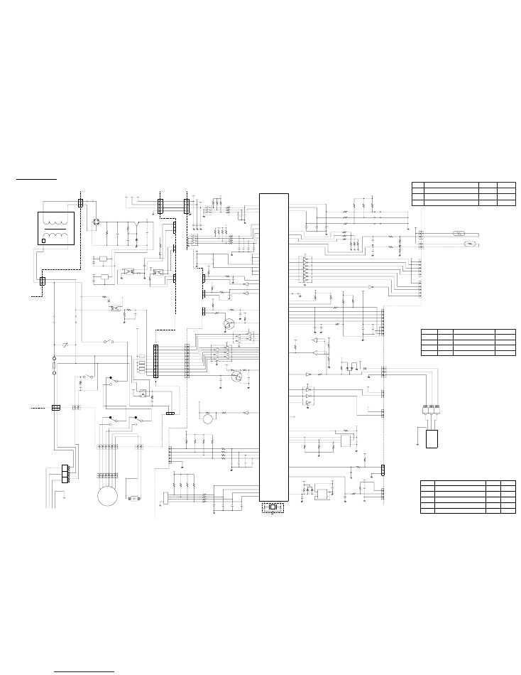
CONTROLLER PCB ASSEMBLY ( MAIN PCB )
K03BZ-0408WSE-C1
POWER SUPPLY PCB
K04CW-0401WSE-P0
Model : ARY30FUAN
2005.04.11
7
INDOOR PCB CIRCUIT DIAGRAM
EX. SIGNAL
CUSTOM CODE
CHANGE 2
CUSTOM CODE CHANGE 1
COMMERCIAL MODE CHANGER
FAN DELAY CHANGER (HEATING)
ROOM TEMP REVISE (COOLING)
Delay
off
+2 deg.
commercial
Function
Commercial mode
on
o deg.
normal
No delay
Fan delay change (heating operation)
Room temp. revise (cooling)
JP
JP3
JP
JP1
JP2
SW1-3
SW1-4 Wired remote controller
Remote controller custom code switching
on
on
off
off
on
on
off
off
weekly type
EZ-09503HSE-R series
EZ-098YHSE-R series
"with thermistor" type
Wireless
B type
D type
C type
A type
SW1 & SW2
-
-
SW1-1 Fan changer
on
off
SW
Function
SW2-3
Room temp. revise (heating)
SW2-1
SW1-2
SW2-2
not auto
0 deg.
-
pulse
auto
+4 deg.
-
edge
Auto restart
Ex. signal function changer
Fan changer
5V
I C 103 H I 2002
14V
VA103
470V
18
14
10
4
3
2
5
1
K101
G2R-1A
DC12V
K101
G5SB-14
DC12V
14V
K104
G5N-1A
K102
G5SB-14
DC12V
K103
G5SB-14
DC12V
W105
SERIAL
CR101
120 / 0.2
TERMINAL BOARD
CN113
B02B-PARK-1
RED
1
2
2
1
2
1
1
1
2
2
3
3
O
I
G
O
I
G
4
3
2
1
1
2
3
4
3
2
1
4
3
2
1
1
2
3
4
5
6
7
8
9
10
1
2
3
4
5
6
7
8
9
10
UL1430 AWG26 GRAY
UL1430 AWG26 GRAY
UL1430 AWG26 GRAY
UL1430 AWG26 GRAY
UL1430 AWG26 GRAY
UL1430 AWG26 GRAY
UL1430 AWG26 GRAY
UL1430 AWG26 GRAY
UL1430 AWG26 GRAY
UL1430 AWG26 GRAY
K102
K110
K101
K103
K104
I NT
RELAY DRIVE
CN116
B10B-PASK-1
WHITE
CN2
B10B-PASK-1
WHITE
14V
5V
Q2
DTC124EKA
C33
0.01
<F>
14V
I C2 (6/7)
uPA2003GR
C32
0.01
<F>
2
3
1
8
16
14
12
13
11
15
9
6
4
2
5
3
1
8
15
13
4
2
14
16
9
3
1
1
3
2
2
1
2
1
2
1
10
7
1
16
+
5V
5V
C1
100/
6.3V
C3
0.1
<F>
5V
C17 - C20
0.1 <F> x 4
C21 - C23
0.1 <F> x 3
C4
0.1
<F>
5V
5V
5V
14V
R53
10K
<1/10W>
C38
0.01
<F>
R55
10K
<1/10W>
R56 1.0K <1/10W>
C34
0.01
<F>
I C2 (1/7)
uPA2003GR
I C3 (1/7)
uPA2003GR
C35
0.01
<B>
I C4 (4/7)
uPA2003GR
Q1
DTA143
R54 180
<1/10W>
5V
5V
12V
14V
SW2
R15 - R17
10K <1/10W> x 3
R18 - R20
1.0K <1/10W> x 3
C
42
-
C
43
0.
1
<
F
>
x
2
SW1
R7 - R10
1.0K <1/10W> x 4
R11 - R14
10K <1/10W> x 4
65
66
73
80
79
78
76
77
59
58
57
56
55
54
53
52
71
14
15
40
36
37
38
39
62
61
51
47
48
49
72
35
31
32
34
18
64
60
3
69
X2
X1
70
1
P03
P27
RESET
2
P57
P54
P55
P56
XT2
P35
P34
P33
P37
P00
P01
P63
P62
P61
P60
P64
P24
P23
I C
P120
P121
P122
P123
P124
P125
P126
P127
P10
P11
P12
14V
JM4
5V
5V
5V
P14
P13
P07
P05
P04
10
6
11
5
3
2
1
74
68
75
7
4
67
33
45
46
30
25
8
9
28
27
26
29
24
23
22
21
20
19
63
50
44
43
42
41
12
13
16
17 P26
P25
P22
P21
P30
P67
P66
P65
P36
P02
P45
P44
P43
P42
P41
P40
P71
P51
P50
P47
P52
P70
P46
P53
P32
P31
P20
VDD0
VDD1
AVRF0
AVRF1
AVSS
VSS0
VSS1
P72
P131
P130
P17
P16
P15
9
8
10
11
12
13
14
15
16
7
6
5
4
3
2
1
7
10
1
2
1
2
1
2
3
4
5
1
2
3
4
5
1
2
3
4
5
6
7
8
1
2
3
1
2
1
2
1
2
3
1
2
3
1
2
3
4
5
1
2
3
6
8
4
7
5
CS
SK
D I
NC
VCC
DO
NC
GND
5V
5V
C13
0.1
<F>
R39
10K
<1/10W>
5V
C10
0.1
<F>
R79 1.0K
<1/10W>
R80
10K
<1/10W>
5V
5V
C11
0.1
<F>
R72
10K
<1/10W>
C12
0.1
<F>
C37
0.01
<F>
I C9
BD4742G
VCC
VOUT
GND
SUB
NC
D1
DAN202K
X1
CSTS0500MG03-T
R40 1.0K <1/10W>
C36
0.01
<F>
R45 - R47
10K <1/10W> x 3
I C7
BR93LC46
R48 10K <1/10W>
14V
14V
14V
I C3 (3/7)
uPA2003GR
I C3 (1/7)
uPA2003GR
8
9
15
14
13
4
3
2
6
11
1
2
3
+
-
I C6-1
BA10393F
R67 390
<1/10W>
12V
5V
R71
10K
<1/10W>
I C6-2
BA10393F
+
-
7
5
6
12V
C39
0.01
<F>
C41
1000P
<R>
R42 47
<1/10W>
12V
D3
D1FS4A
D2
DA226U
R68
15.4K
<1/10W>
R69
28K
<1/10W>
R70
10K
<1/10W>
+
C2
10/
25V
C40
0.01
<F>
I C3 (1/7)
uPA2003GR
R49 10K
<1/10W>
R50 10K
<1/10W>
R41 1.0K <1/10W>
R43
R44
10K <1/10W> x 2
I C5 (7/7)
uPA2003GR
R62 - R64
10K <1/10W> x 3
R57 - R59
1.0K <1/10W> x 3
5V
5V
R73
10K
<1/10W>
R74 1.0K
<1/10W>
R75 1.0K
<1/10W>
R76 1.0K
<1/10W>
C16
0.1
<F>
C14
0.1
<F>
C15
0.1
<F>
R60 1.0K
<1/10W>
R61 1.0K
<1/10W>
R65
10K
<1/10W>
R66
49.9K
<1/10W>
14V
C8
0.1
<F>
C9
0.1
<F>
JM1
JM3
JM2
10K <1/10W> x 3
R3
R1
R2
JM101
+
5V
12V
C112
0.1
<F>
C111
10/
25V
I C101
NJM7805
I C102
NJM7812
PRIMARY
SECONDARY
D101
D2SB20
2
3
1
4
2
1
JM103
UL1430 AWG22 RED
UL1430 AWG22 RED
+
+
R102
10K
<1/4W>
C107
1000
/50V
R103
1.0K
<1/2W>
C108
10/
25V
14V
Q101
2SC1932
+ C109
10/
25V
D102 MTZJ15C
CN114
B3B-XH-AM
WHITE
5V 12V 14V
CN105
B04B-PASK-1
WHITE
CN104
B2B-XARK-1-A
RED
CN103
B2P3-VH-B-R
RED
2
1
U
L1
01
5
A
W
G
22
V
IO
LE
T
U
L1
01
5
A
W
G
22
V
IO
LE
T
POWER TRANSFORMER
EZ-0970WWE-T
DC SUPPLY
4
3
2
1
UL1430 AWG26 GRAY
UL1430 AWG26 GRAY
UL1430 AWG26 GRAY
UL1430 AWG26 GRAY
CN1
B04B-PASK-1
WHITE
EX. I N
EX. OUT
CN115
B2B-XH-AM
WHITE
14V
FL101
BL02RN1
R
10
7
3
30
<
1/
4W
>
5V
C114
0.01
<B>
FL102
BL02RN1
PC103
TLP621
<GB>
R108
330
<1/4W>
PC102
TLP621
<GB>
JM102
FH102
FH101
F101
3.15A
<BET>
L N
AC I N
CN101
B2P3-VH-B-C
BLACK
1
2
U
L1
01
5
A
W
G
18
B
LA
C
K
U
L1
01
5
A
W
G
18
W
H
IT
E
U
L1
01
5
A
W
G
20
R
E
D
12
5
5
1
2
3
4
8
4
2
1
C
SW3
5V
C24 - C27
0.1 <F> x 4
R21 - R24
1.0K <1/10W>
x 4
R25 - R28
10K <1/10W> x 4
TEST
CN3
B5P-SHF-1AA
WHITE
1
2
3
4
5
1
2
1
2
3
4
5
6
CN107
B6P11-VH-B
WHITE
CN108
B2P3-VH-B-Y
YELLOW
U
L1
01
5
A
W
G
20
W
H
IT
E
U
L1
01
5
A
W
G
20
W
H
IT
E
U
L1
01
5
A
W
G
22
P
U
R
P
LE
U
L1
01
5
A
W
G
22
P
IN
K
U
L1
01
5
A
W
G
22
R
E
D
U
L1
01
5
A
W
G
22
W
H
IT
E
U
L1
01
5
A
W
G
22
B
LA
C
K
U
L1
01
5
A
W
G
22
B
LU
E
1
2
CN109
B2P3-VH-B-E
BLUE
DRAIN PUMP
5V
BZ1
R29 - R32
10K <1/10W> x 4
R33 - R36
1.0K <1/10W> x 4
C28 - C31
0.01 <F> x 4
I C3 (1/7)
uPA2003GR
R38 1.0K
<1/10W>
R37 1.0K
<1/10W>
B Z
FAN
MOTOR
FAN CAPACITOR
10.0uF
440V
2(N)
1
3
OUTDOOR UNIT
REMOTE CONTROL UNIT
EARTH WIRE
3 2 1
TERMINAL BOARD
CN10
B3P-VH-B
WHITE
FEED BACK
FLOAT SWITCH
CN9
B3B-XARK-1-A
RED
HEATER
CN15
B02B-PA0K-1
ORANGE
FRESH AIR
CN14
B02B-PAMK-1
GREEN
CN6
B3B-XAKK-1-A
BLACK
U
L1
43
0
A
W
G
22
W
H
IT
E
U
L1
43
0
A
W
G
22
R
E
D
U
L1
43
0
A
W
G
22
B
LA
C
K
DISPLAY
CN13
B8B-XASK-1-A
WHITE
CN12
B5B-XARK-1-A
RED
LOUVER (R / L )
LOUVER (U / D )
CN11
B5B-XASK-1-A
WHITE
CN8 B2B-XASK-1-A
WHITE
CN7 B2B-XAKK-1-A
BLACK
GRAY
GRAY
BLACK
BLACK
ROOM TEMPERATURE THERMISTOR
PIPE TEMPERATURE THERMISTOR
R4 - R6
1.0K <1/10W>
x 3
8
7
6
5
4
3
2
1
6
5
4
1
2
3
UL1430 AWG26 GRAY
UL1430 AWG26 GRAY
EX. SIGNAL
CN106
B02B-PAKK-1
BLACK
CN5
B02B-PAKK-1
BLACK
EX. SIGNAL
SERIAL
CN4
B02B-PARK-1
RED
NEW SERIAL
CN16
B02B-PASK-1
WHITE
R77 10K
<1/10W>
R78 390
<1/10W>
NC
I C 1
uPD780058BGK
-A42-9EU-A
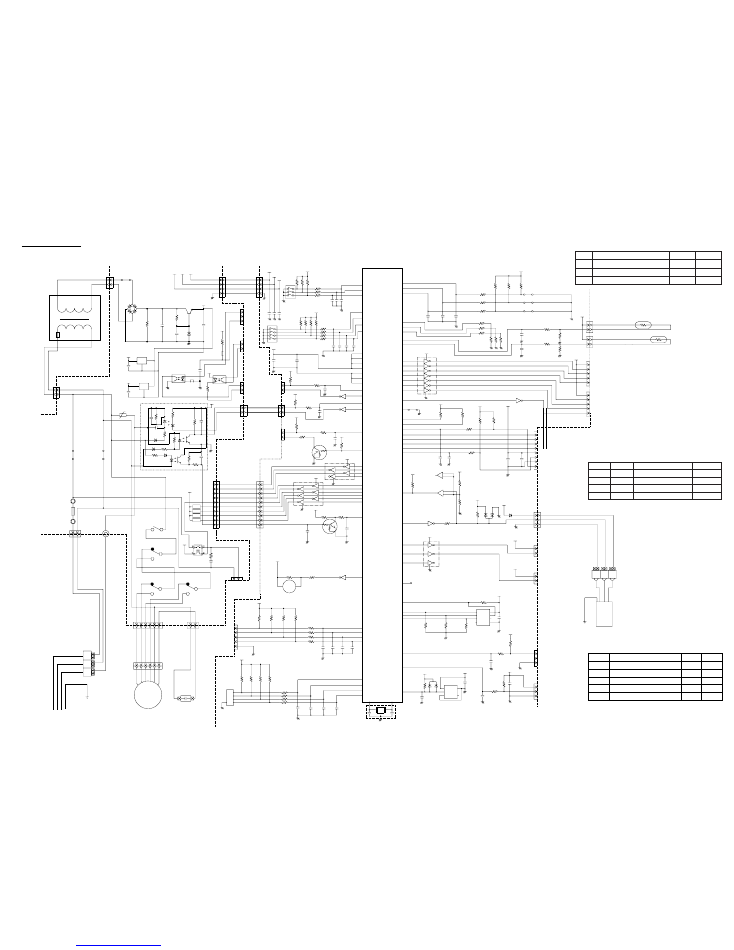
CONTROLLER PCB ASSEMBLY ( MAIN PCB )
K03BZ-0409HSE-C1
POWER SUPPLY PCB
K04CW-0400HSE-P0
Model : ARY30UUAN
COMMERCIAL MODE CHANGER
FAN DELAY CHANGER (HEATING)
ROOM TEMP REVISE (COOLING)
EX. SIGNAL FUNCTION CHANGER
AUTORESTART CHANGER
ROOM TEMP REVISE ( HEATING )
FAN CHANGER 2
FAN CHANGER 1
CUSTOM CODE
CHANGE 2
CUSTOM CODE CHANGE 1
2005.04.11
8
JP
Delay
off
+2 deg.
commercial
Function
Commercial mode
on
o deg.
normal
No delay
Fan delay change (heating operation)
JP3
Room temp. revise (cooling)
JP
JP1
JP2
SW1-3
SW1-4 Wired remote controller
Remote controller custom code switching
on
on
off
off
on
on
off
off
weekly type
EZ-09503HSE-R series
EZ-098YHSE-R series
"with thermistor" type
Wireless
B type
D type
C type
A type
SW1 & SW2
-
-
SW1-1 Fan changer
on
off
SW
Function
SW2-3
Room temp. revise (heating)
SW2-1
SW1-2
SW2-2
not auto
0 deg.
-
pulse
auto
+4 deg.
-
edge
Auto restart
Ex. signal function changer
Fan changer
POWER SOURCE
230V
50Hz
POWER RELAY
EL12D1-F (M)
3.5 uF, 450V
CONTROLLER PCB ASSEMBLY ( MAIN PCB )
EZ-0028HUE-C
Model : AOY30UNBWL
OUTDOOR PCB CIRCUIT DIAGRAM
2005.04.11
9
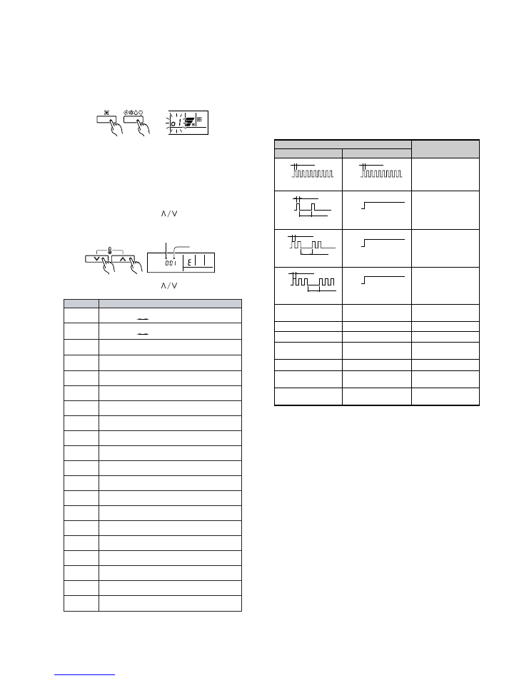
SU MO TU WE TH FR SA
(1) Stop the air conditioner operation.
(2) Press the master control button and the fan control button simultane-
ously for 2 seconds or more to start the test run.
Unit number (usually 0)
Error code
(3) Press the start/stop button to stop the test run.
[SELF-DIAGNOSIS]
When the error indication E:EE is displayed, follow the following items
to perform the self-diagnosis. E:EE indicates an error has occurred.
1. REMOTE CONTROLLER DISPLAY
1) Stop the air conditioner operation.
2) Press the set temperature buttons
simultaneously for 5 sec-
onds or more to start the self-diagnosis.
Refer to the following tables for the description of each error code.
Test run display
(3) Press the set temperature buttons
simultaneously for 5 sec-
onds or more to stop the self-diagnosis.
Ex. Self-diagnosis
Room temperature sensor open
Room temperature sensor short-circuited
Indoor heat exchanger temperature sensor open
Indoor heat exchanger temperature sensor short-
circuited
Outdoor heat exchanger temperature sensor open
Outdoor heat exchanger temperature sensor short-
circuited
Power source connection error
Float switch operated
Outdoor temperature sensor open
Outdoor temperature sensor short-circuited
Discharge pipe temperature sensor open
Discharge pipe temperature sensor short-circuited
Outdoor high pressure abnormal
Discharge pipe temperature abnormal
Model abnormal
Indoor fan abnormal
Outdoor signal abnormal
Outdoor EEPROM abnormal
02
03
04
05
06
07
08
09
0A
0b
0c
0d
0E
0F
11
12
13
14
Error code
Error contents
Communication error
(indoor unit
remote controller)
Communication error
(indoor unit
outdoor unit)
00
01
ERROR CONTENTS
When a malfunction occurs in the outdoor unit, the LEDs on the circuit
board light to indicate the error. Refer to the following table for the de-
scription of each error according to the LEDs.
When the fault is cleared, the LED lamp goes off.
However, for discharge pipe temperature abnormal and high pressure
abnormal, the LED lamp lights continuously for 24 hours, as long as the
power is not turned off.
Quick flash continued
Quick flash continued
1 quick flash repeated
Lighting continued
2 quick flash repeated
Lighting continued
3 quick flash repeated
Lighting continued
4 quick flash repeated
Lighting continued
5 quick flash repeated
Lighting continued
Communication signal error
6 quick flash repeated
Lighting continued
7 quick flash repeated
Lighting continued
8 quick flash repeated
Lighting continued
High pressure abnormal
5 quick flash repeated
Dislighting continued
Discharge temperature
abnormal (24h)
6 quick flash repeated
Dislighting continued
Error display
LED1
LED2
Error contents
0.1 sec.
OFF
ON
0.1 sec.
OFF
ON
0.5 sec.
2 sec.
OFF
ON
OFF
ON
0.5 sec.
2 sec.
OFF
ON
OFF
ON
0.5 sec.
2 sec.
OFF
ON
OFF
ON
2. OUTDOOR UNIT
ERROR : Heat & Cool model (Reverse cycle) only
Model abnormal or
EEPROM abnormal
Power source
connection error
Discharge temperature
sensor error
Outdoor heat
exchanger temperature
sensor error
Outdoor temperature
sensor error
Indoor unit error
Discharge temperature
abnormal
High pressure
abnormal (24h)
2005.04.11
10
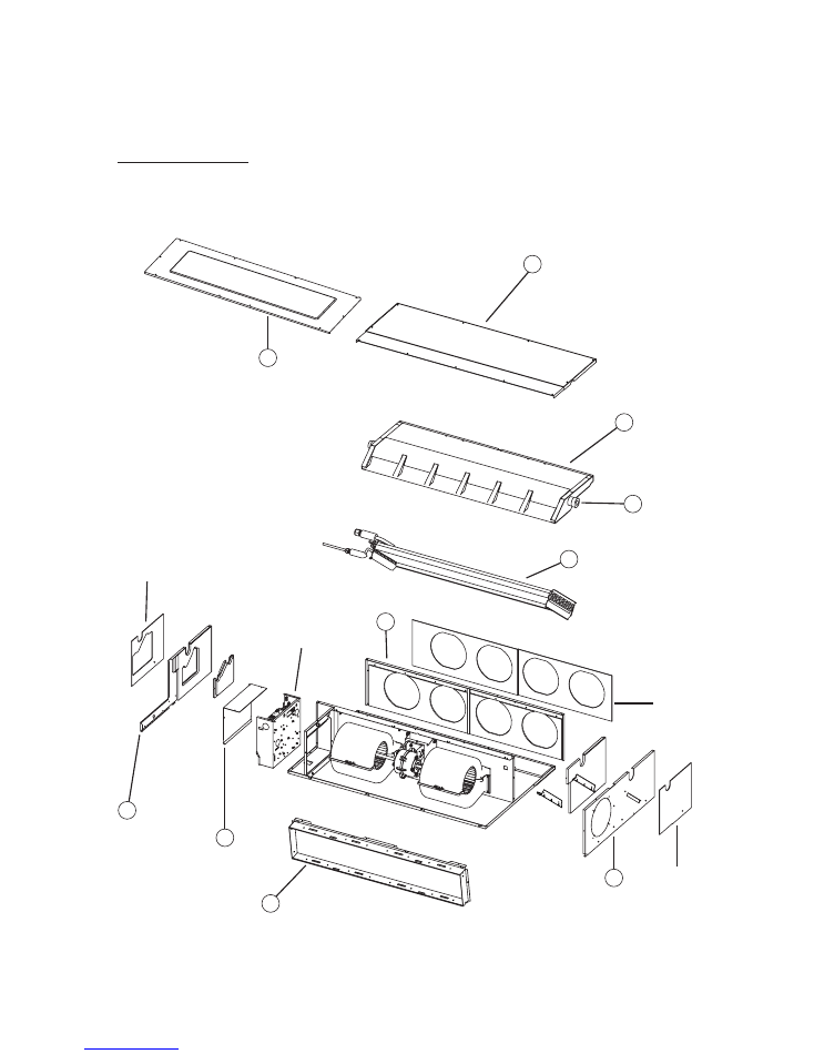
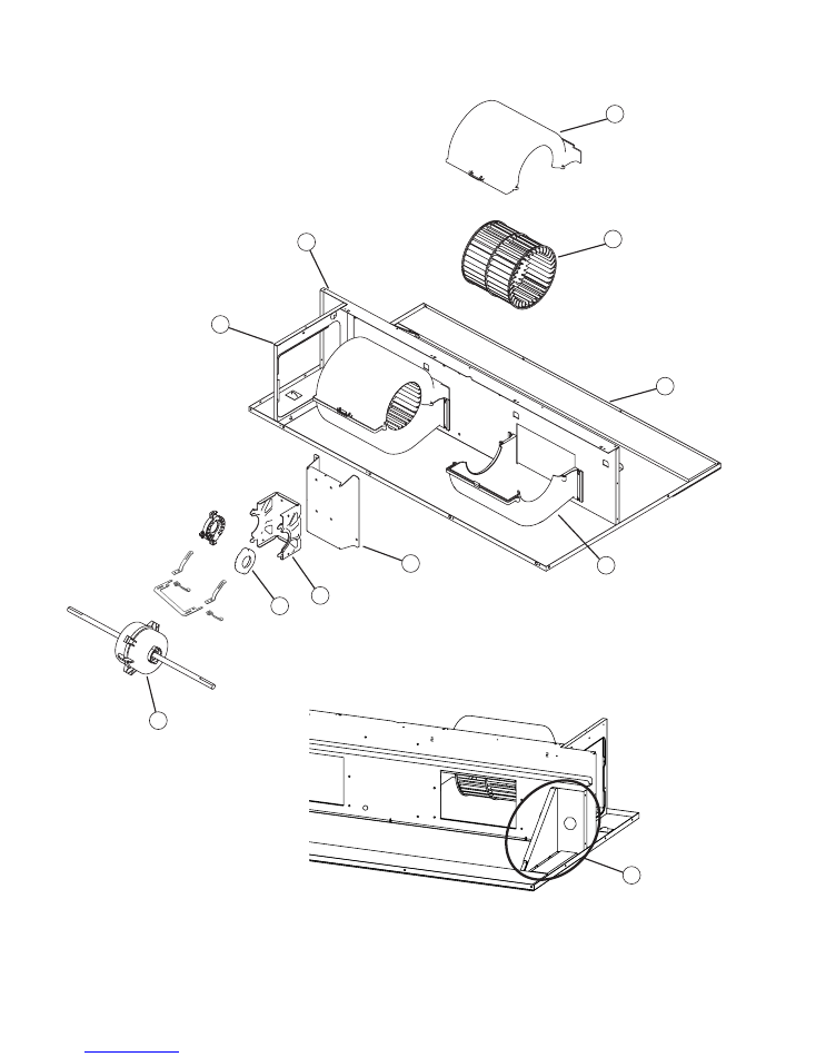
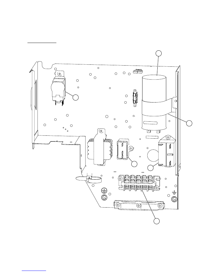
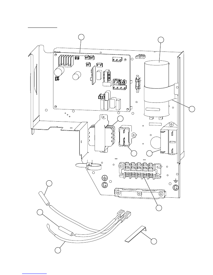
DISASSEMBLY ILLUSTRATION
Models : ARY30FUAN
ARY30UUAN
20
73
146
764
75
74
72
325
324
160
Insulation
Insulation
Control Box
Insulation
2005.04.11
11
111
56
108
110
41
150
40
67
139
138
164
2005.04.11
12
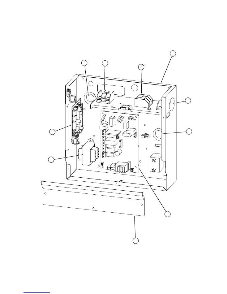
816
817
287
236
553
956
223
288
287
875
2005.04.11
13
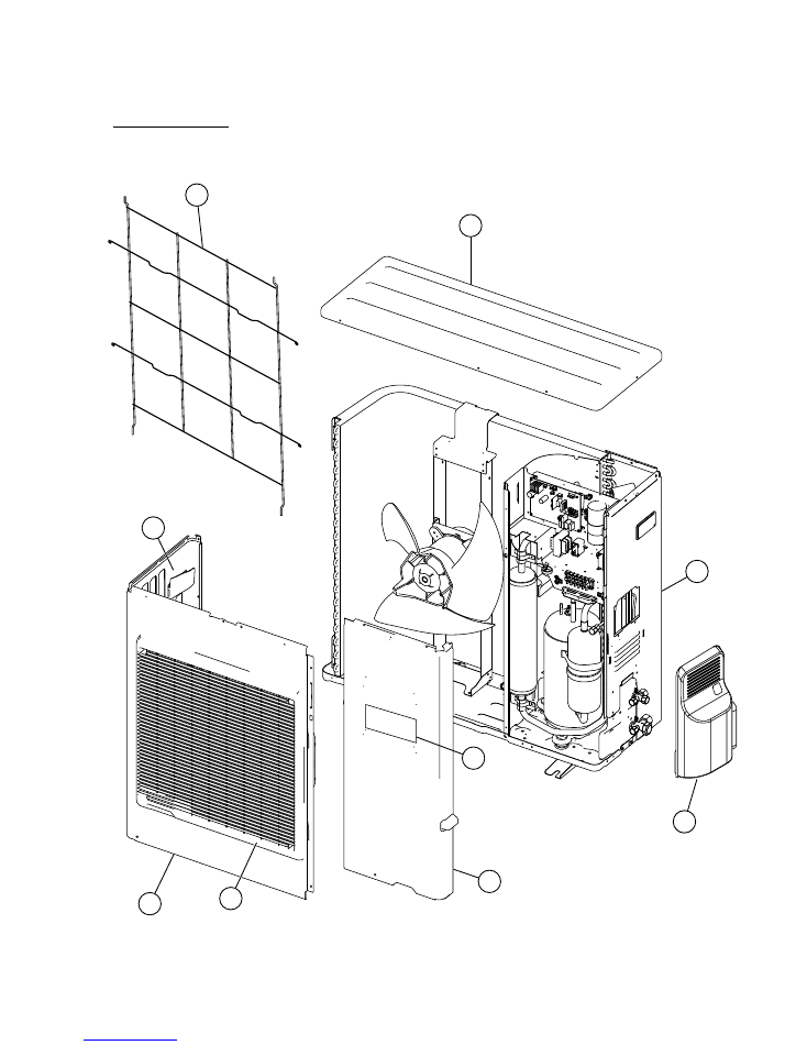
1
34
2
3
4
5
35
6
7
Models :
AOY30FNBWL
AOY30UNBWL
2005.04.11
14
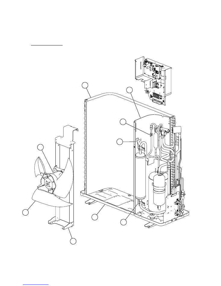
13
36
12
11
10
9
8
14
13
Models :
AOY30FNBWL
AOY30UNBWL
2005.04.11
15
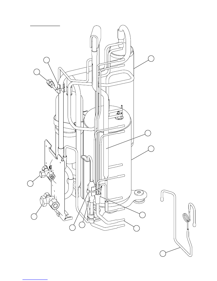
23
38
24
39
16
15
21
37
18
17
22
37
Model :
AOY30FNBWL
2005.04.11
16

22
37
37
23
38
40
20
18
19
32
41
42
21
15
16
24
17
39
Model :
AOY30UNBWL
2005.04.11
17
27
29
26
33
31
28
Model :
AOY30FNBWL
2005.04.11
18
29
46
43
44
45
Model :
AOY30UNBWL
27
26
25
31
30
28
2005.04.11
19
When you order parts, please make a photocopy of this page
and fill the number of the parts in the "Order" column.
PARTS LIST
INDOOR UNIT
ARY30FUAN
ARY30UUAN
Ref.
No.
Description
Ord.
Q'ty
Part No.
20
Control Cover -A Sub Assy
9374516018
40
Motor Mount
9374281015
41
Bracket Motor Assy
9374230013
56
Sirocco Fan Assy
9356531022
67
Rubber
313659068604
72
Cabinet L Sub Assy
9374509010
73
Cabinet R Sub Assy
9374508013
74
Intake Cover Sub Assy
9374512010
75
Outlet Panel Sub Assy
9374510016
108
Base Sub Assy
9374504015
110
Casing A
9374233014
111
Casing B
9374234011
138
Separatewall Assy
9374228010
139
Panel (Control Box) Sub Assy
9374506019
146
Evaporator Total Assy
9374517015
150
Bracket (Eva) -R
9374207015
160
Drain Pan Sub Assy
9374513017
164
Motor, Induct
9600830086
223
Control Box -A
9374219018
236
Controller PCB Assy
9705246096
287
Cap (Power)
9352173011
324
Main Panel Sub Assy
9374511013
325
Intake Frame Assy
9374216017
553
Transformer (Power)
9704129017
764
Drain Cap
9356541007
816
Terminal 3P
9703345012
817
Terminal 3P
9306489045
875
Power PCB Assy
9705668010
956
Control Cover -B
9374222018
Thermo. Spring -A
313728262708
Thermistor Assy -Room
9703299025
Thermistor Assy -Pipe
9703297021
Remotecontroller Assy
9372266014
RFM (Motor Band)
9374646012
Motor Band -B
9374648023
Control Box -B
9374220014
Motor Band -A Assy
9374647019
Wire with Connector
9704856012
Wire with Connector
9705245020
Wire with Connector
9705243026
Wire with Connector
9705244023
9374516018
9374281015
9374230013
9356531022
313659068604
9374509010
9374508013
9374512010
9374510016
9374504015
9374233014
9374234011
9374228010
9374506019
9374517015
9374207015
9374513017
9600830086
9374219018
9705246089
9352173011
288
One Touch Bush
9374407019
9374407019
9374511013
9374216017
9704129017
9356541007
9703345012
9306489045
9705668027
9374222018
313728262708
9703299025
9703297021
9372266021
9374646012
9374648023
9374220014
9374647019
9704856012
---
9705243026
9705244023
2010.01.05
20
When you order parts, please make a photocopy of this page
and fill the number of the parts in the "Order" column.
OUTDOOR UNIT
Ref. Description
Part number
AOY30UNBWL
Ref. Description
Part number
AOY30FNBWL
1
9374417018
Top Panel Sub Assy
2
9374094066
Front Panel
3
9374330010
Fan Guard
4
9374173013
Grip Side
5
9374415038
Service Panel Sub Assy
6
9351355005
Emblem-Rear
7
9374416035
Right Panel Sub Assy
8
9374418039
Motor Bracket Sub Assy
9
9366378013
Propeller Fan Assy
10
9601671060
Fan Motor
11
9374433056
Condenser Assy
12
9374413034
Separate Wall Sub Assy
13
9355350006
Accumulator Support-B
14
9374166046
Base Assy
15
9372205044
3-Way Valve Assy
16
9372205075
3-Way Valve Assy
17
9372558089
Compressor Assy
18
9374338016
Accumulator
19
9372369012
Muffler
20
9900163013
4-Way Valve
32
9900165055
Solenoid
21
9374274024
Check Valve Assy
22
9372524015
Strainer Assy
23
9369128004
Distributor
24
9372197325
Capillary Assy
25
9704299024
Controller PCB Assy
26
9900269081
Running Capacitor
27
9351770013
Capacitor Clamp
28
9900074029
Main Relay
29
9900203023
Terminal 5P
30
9900039011
Transformer
31
9900270049
Capacitor (Fan)
34
9374255030
Protective Net
35
36
46
37
41
45
43
42
40
39
38
44
9374174010
Valve Cover
9371512013
Cover Gasket (Comp)
9371511016
Terminal Cover (Compressor)
9351049010
Rubber Seat (Compressor)
9374430031
Compressor Cover
9357804002
Thermostat Holder
0000361224
Varistor
0600280154
Varistor (Arrester)
313394274808
Capillary Holder Rubber
313728262708
Thermo. Spring A
9900200015
Relay on PCB
9900037048
Thermistor (Out Temp)
9900043049
Heat Exchanger Thermistor
9361140257
Belt Heater
313728251908
4-Way Valve Rubber
9300301015
Special Nut M5 (compressor)
9372246054
Discharge B Assy
9374469017
Inlet Pipe (Condenser) C Assy
9374266050
Outlet Pipe (Condenser) A Assy
9373461067
Inlet Pipe (Condenser) A Assy
9900038038
Thermistor-Discharge
1
9374417018
Top Panel Sub Assy
2
9374094066
Front Panel
3
9374330010
Fan Guard
4
9374173013
Grip Side
5
9374415038
Service Panel Sub Assy
6
9351355005
Emblem-Rear
7
9374416035
Right Panel Sub Assy
8
9374418039
Motor Bracket Sub Assy
9
9366378013
Propeller Fan Assy
10
9601671060
Fan Motor
11
9374433063
Condenser Assy
12
9374413034
Separate Wall Sub Assy
13
9355350006
Accumulator Support-B
14
9374166046
Base Assy
15
9372205044
3-Way Valve Assy
16
9372205075
3-Way Valve Assy
17
9372558089
Compressor Assy
18
9374338016
Accumulator
21
9374274024
Check Valve Assy
22
9372524015
Strainer Assy
23
9369128004
Distributor
24
9372197349
Capillary Assy
26
9900269081
Capacitor Plastic
27
9351770013
Capacitor Clamp
28
9900074012
Relay
29
35
9900203023
Terminal 5P
31
33
34
9900270049
Capacitor (Fan)
9371512013
Cover Gasket (Comp)
9371511016
Terminal Cover (Compressor)
9351049010
Rubber Seat (Compressor)
9374430031
Compressor Cover
9374255030
Protective Net
9300301015
Special Nut M5 (compressor)
9372264089
Discharge A Assy
9374469017
Inlet Pipe (Condenser) C Assy
9374174010
Valve Cover
39
38
37
313394274808
Capillary Holder Rubber
9374266050
Outlet Pipe (Condenser) A Assy
9373461067
Inlet Pipe (Condenser) A Assy
9900275013
Thermostat Outdoor
2007.05.18
21
4
4
4
2
1
1
(large)
1
(small)
1
2
1
1
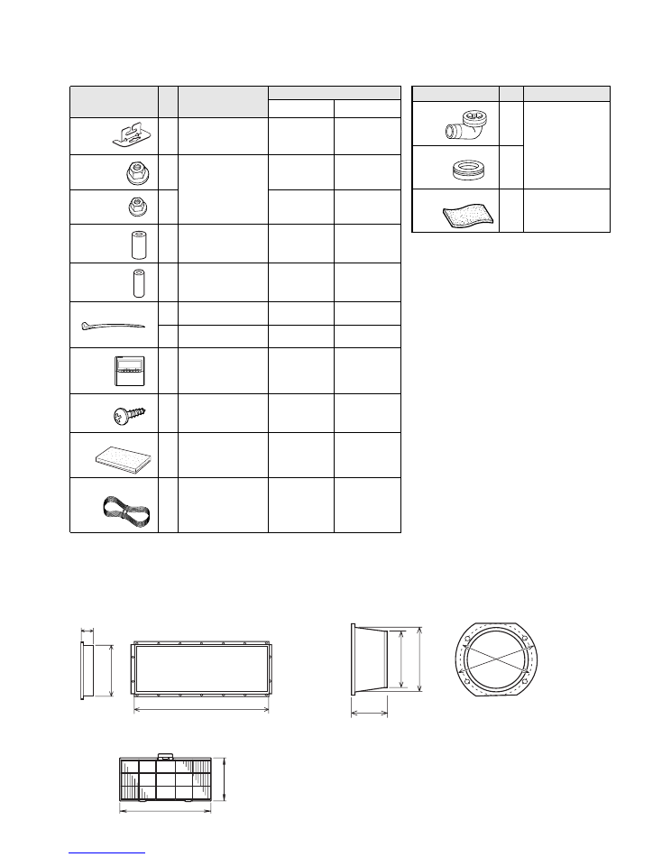
Name and Shape Q'ty
Application
ARY30FUAN
ARY30UUAN
Hanger
Special nut A
(large flange)
Special nut B
(small flange)
Coupler heat
insulation
(large)
Coupler heat
insulation
(small)
Nylon fastener
Remote
control unit
Tapping screw
Drain hose insulation
For suspending the indoor
unit from ceiling
For suspending the indoor
unit from ceiling
For indoor side pipe joint
(large pipe)
For indoor side pipe joint
(small pipe)
For fixing the drain hose
For fixing the remote
controller cord
For installing the remote
control unit cord clamp
Insulates the drain hose
and vinyl hose connection
9356563009
313005446653
313005446759
9350716029
9352766015
312300787605
9372266021
0700181108
313806217708
9356563009
313005446653
313005446759
9350716029
9352766015
312300787605
313361275805
31361275805
9372266014
0700181108
313806217708
9372714010
9372714010
INDOOR UNIT ACCESSORIES
STANDARD ACCESSORIES
Remote controller
cord
Part No.
2005.04.11
22
OUTDOOR UNIT ACCESSORIES
OPTIONAL PARTS
Name and Shape
Q'ty
Application
For outdoor unit drain
piping work (May not be
supplied, depending on
the model.)
For filling in a gap at the
entrance of connection
cords
1
2
1
Drain pipe
Drain cap
Insulation (seal)
When connecting the square duct and round duct, use the optional square flange or round flange and flexible duct.
Square flange
Round flange
Model name : UTD–SF045T (P/N 9098180007)
Model name : UTD–RF204 (P/N 9093160004)
Long-life filter
Simple remote controller
Model name : UTD–LF25NA (P/N9079892004)
Model name : UTB–YPB (P/N9077582006)
Remote sensor
Model name : UTD–RS100 (P/N9072619004)
40 mm
20
4
m
m
1065mm
85 mm
ø
19
5
m
m
ø
20
5
m
m
ø225 m
m
ø23
5 m
m
507 mm
23
9
m
m

0502G2755