Full Text Searchable PDF User Manual
A1

A1
SAFETY PRECAUTIONS
Warning:
Read and understand all instructions in this
manual. Use appropriate personal safety equipment
including hearing and eye protection when using the
scanner in or near the vehicle engine compartment.
Failure to comply with this manual may result in
accidents involving fire, electrical shock, or serious
personal injury, etc.
Electrical
* Do not allow any object to be pressed in the cable
assembly; Do not allow the cable assembly to be
pinched; Keep the cable assembly away from heat, oil,
sharp edges, or moving parts; Replace damaged cables
immediately; Damaged cables increase the risk of
electrical shock; Do not disassemble the scanner; This
manual is not for repairing units; Please properly
dispose used batteries; Do not incinerate batteries;
Consult your local waste authority for available recycling
and/or disposal options.
Use and Care
* Stay alert, and pay attention to what you are doing.
Use common sense when the scanner is operated.
When some functions are to be tested, the engine
should be running. Children and visitors should keep a
safe distance from the work area.
* Keep the scanner dry, clean, and free from oil and
grease. Use a mild detergent on a clean cloth to wipe
the dirt off when necessary.

A2
Service
Service must only be performed by repair technicians of
FCAR. Service & Maintenance by unqualified personnel
may result in injury and damage to the unit, and may
void your warranty. Refer to the Product Warranty
Policy section of this manual.
A3
INTRODUCTION
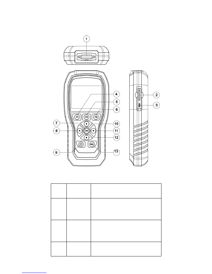
Appearance and Key Descriptions
Serial
No.
Name
Application
①
Main
Testing
Cable
Connection interface connects
vehicle communication cable
during the vehicle diagnosis.
②
SD Card
Installation interface of SD card
(vehicle testing diagnosis software
is installed in the SD card)
③
USB Port
Use to connect an external printer
(spare).
A4
④
[F1]
Function key, for advanced
function menu use
⑤
[F2]
Function key, for advanced
function menu use
⑥
[F3]
Function key, for advanced
function menu use
⑦
OK
confirm
⑧
←
left
⑨
screen brightness
⑩
↑
up
11
→
To the right
12
↓
down
13
ESC
return
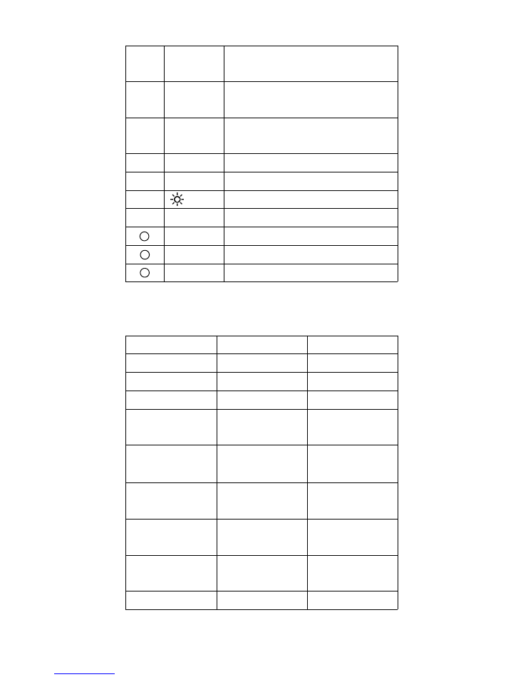
Host Parameters
Hardware
Parameter
Type/Unit
CPU
120MHZ
LPC1788
Display
3.5 inch LCD
Resolution Ratio
320x240
Dot matrix
SD Card
Interface
2GB/4GB/8GB
National
Standard
Diagnostic
Interface
Main line
DB15
Operating
Voltage
11~28V
V
Operating
Current
<
500 mA
mA
Storage
Temperature
-20
℃
~60
℃
℃
Dimension
224.5*106.5*43
mm

A5
Functions
Class 4-Class 8 truck coverage featuring "Automatic
Protocol Search".
HD J1708 and J1939 CAN, Engine, Transmission/ABS
coverage, etc.
CAT Support: CAT Truck/Bus, CAT Construction,
CAT Power Equipment, CAT Agricultural, CAT Industrial,
CAT On/Off Highway
* General Functions (Including Global OBD II coverage):
- Read ECU Information
- Read and Erase Fault codes
- Read Live Data
- Read Freeze Frame
- Graph Live Data
- Screenshot Function
* Graph live data such as:
- Engine speed
- Engine ECU temperature
- Percent acceleration pedal position
- Engine intercooler temperature
- Engine coolant temperature
- Battery volts
- Alternator volts
- Ambient air temperature
- Air inlet temperature
Set measurement units in SAE English/Metric.
Internet upgrade

B1
Application
Passenger cars and Business vehicles
Tow trucks, recreational vehicles, cement trucks, dump
trucks, garbage trucks, buses, step vans, municipal
vehicles, refrigerated trucks, and conventional trucks
.
Heavy-Duty Standard compliant construction, marine,
agriculture, and other industrial machinery and
equipment.
Diesel power plant configurations
CAT Support: CAT Truck/Bus, CAT Construction, CAT
Power Equipment, CAT Agricultural, CAT Industrial, CAT
On/Off Highway
SAE J1850PWM, SAE J1850 VPW, IS0 14230-4, IS0
9141-2,IS0 15765-4,SAEJ1708
,
SAE J1939
The purpose of this manual is to guide you to use the
scanner successfully. It is not a repair manual for your
vehicle. For specific information on troubleshooting
your vehicle, please refer to the owner’s manual or
various other repair manuals.
OPERATION
Connect the scanner to your vehicle: F506
communicates with the computer in your vehicle
through a main-line connection. One end of the cable is
plugged into the connector on DB15 of F506 and the
other end to the adaptor, which is plugged in to the
diagnostic socket on your vehicle.
CAUTION: The operating voltage of F506 is within
11V-28V, please make sure the output voltage of the
diagnostic socket on your vehicle is 11V - 28V.
Turn the vehicle ignition key to ON or start the engine,
and then the F506 will automatically start.(Fig.1&Fig.2)
B2
DIAGNOSTIC & OPERATING INTERFACE
DIAGNOSE
Select Menu: Select the [DIESEL OBD] and press (OK)
button; The HD Code
Ⅱ
includes categories of the
software: SAE J1939, SAE J1708
Select Menu: Select the [CAT] and press (OK) button;
The F506 includes categories of software: CAT Truck/Bus,
CAT Construction, CAT Power Equipment, CAT
Agricultural, CAT Industrial, CAT On/Off Highway
Select the [OBDII] and press (OK) button; The F506
includes categories of software: IS0 14230, IS015765,
SAE J1850, IS0 9141-2, IOS 15765-4
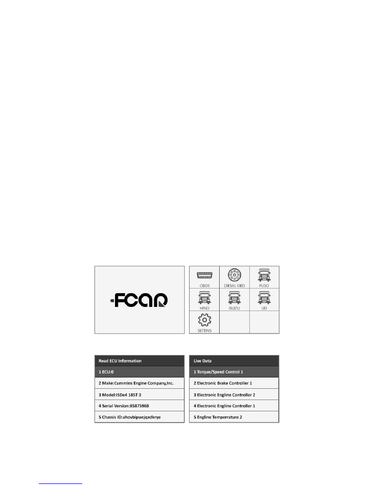
OPERATING INTERFACE
(Fig.1: Boot Screen)
(Fig.2: Main Interface)
(Fig.3: Read ECU Info)
(Fig.4: Live Data View)
B3
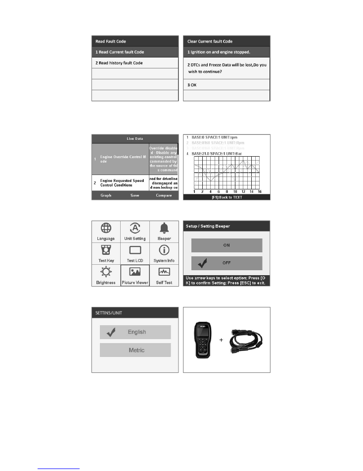
(Fig.5: Read Fault Code)
(Fig.6: Read Current Fault
Code)
(Fig.7: Live Data View)
(Fig.8: Graph Live data)
(Fig.9: Setting Interface)
(Fig.10: Beeper On/Off)
(Fig.11: Unit sitting)
(Fig.12: Device Self-test)

B4
Caution
Make sure the connector is firmly attached.
Keep the vehicle ignition key ON or the engine running.
Accessories connector:
OBD-16 pin connector supports J1708/J1587 or J1939
protocol.
DIESEL-9 pin connector supports J1708/J1587 protocol
and J1939 protocol.
DIESEL-6 pin connector supports only J1708/J1587
protocol.
CAT-9 pin connector supports J1708/J1587 or J1939
protocol.
TROUBLESHOOTING GUIDE
If the F506 fails to connect to the vehicle:
1. Make sure the vehicle ignition key is in the ON
position;
2. Make sure pins in connectors are not bent and
contacted;
3. Make sure the cable connectors are plugged in firmly;
4. Make sure the diagnostics connector is clean.
How to self-test the F560:
Connect the power interface of the main test line, and
then connect it to the 12V DC power supply. The F506
starts and then enters the system settings/SELF-TEST to
test if the F560 is normal or abnormal (refer to Fig.12).

B5
Shenzhen Fcar Technology Co., Ltd.
Headquarters: 8F, Chuangyi Bldg., No. 3025 Nanhai
Ave., Nanshan, Shenzhen, China 518060
Factory: West 1F, Bldg. B, Hengchao Industrial Park,
Tangtou North Ave., Bao'an, Shenzhen, China 518108
Tel: 0086-755-82904730
Fax: 0086-755-83147605
E-mail:marketing@szfcar.com
B6