Full Text Searchable PDF User Manual
740 D
12
ENGLISH
CONTROL BOARD 740 D
1. WARNINGS
Before attempting any work on the control board (connections, maintenan-
ce), always turn off power.
Install, upstream of the system, a differential thermal breaker with adequate
tripping threshold.
Connect the earth cable to the appropriate terminal on the J7 connector
of the equipment (see fig.2).
Always separate power cables from control and safety cables (push-but-
ton, receiver, photocells, etc.). To avoid any electric noise, use separate
sheaths or a shielded cable (with earthed shield).
2. TECHNICAL SPECIFICATIONS
Power supply (+6% -10% V)
230 V- - 50 Hz
(115 V- - 60 Hz*)
Absorbed power
10 W
(10 W*)
Motor max. load
1000 W
(1200 W*)
Accessories max. load
0,5 A
(0.5 A*)
Operating ambient tempe-
rature
-20 °C +55 °C
Protection fuses
2 (see fig. 1)
Function logics
Automatic / “Stepped” automatic / Semi-au-
tomatic / Safety devices / Semi-automatic B
/ Dead-man C / “Stepped” semi-automatic
/ Mixed Log. B+C
Work time
Programmable (from 0 to 4 min.)
Pause time
Programmable (from 0 to 4 min.)
Thrust force
Adjustable over 50 levels
Terminal board inputs
Open / Pàartial opening / Safety devices
at opng. / Safety devices at clsng. / Stop /
Edge / Power supply + Earth
On-connector inputs
Opening and closing limit-switches / Enco-
der
Terminal board outputs
Flashing lamp - Motor - 24 Vdc accessories
power supply - 24 Vdc indicator-light / Timed
output. - Fail safe
Rapid connector
5-pin card connection for Minidec, Decoder
or RP receivers
Programming
3 keys (+, -, F) and display, “basic” or
“advanced” mode
Basic mode programmable
functions
Function logic - Pause time - Thrust Force
- Gate direction
Advanced mode program-
mable functions
Torque at initial thrust - Braking - Fail safe
- Pre-flashing - Indicator-light/Timed output -
Opening and closing safety devices logic -
Encoder - Decelerations - Partial opening
time - Work time - Assistance request - Cycle
counter
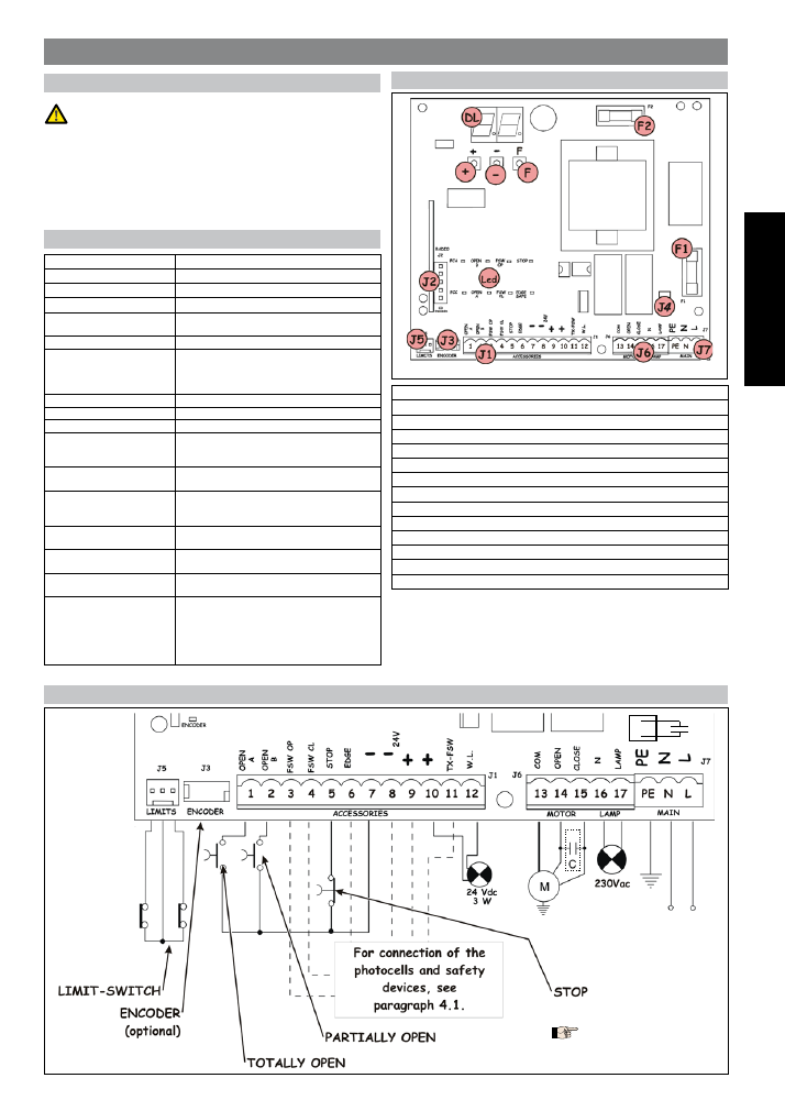
3. LAYOUT AND COMPONENTS
DL
SIGNALLING AND PROGRAMMING DISPLAY
Led
INPUTS STATUS CONTROL LED
J1
LOW VOLTAGE TERMINAL BOARD
J2
CONNECTOR FOR DECODER/MINIDEC/RP RECEIVER
J3
ENCODER CONNECTOR
j4
CAPACITOR CONNECTOR
J5
LIMIT -SWITCH CONNECTOR
J6
MOTORS AND FLASHING LAMP CONNECTION TERMINAL BOARD
J7
POWER SUPPLY TERMINAL BOARD 230Vac
(115Vac*)
F1
MOTORS AND TRANSF. PRIMARY FUSE (F 5A)
(F 10A*)
F2
LOW VOLTAGE AND ACCESSORIES FUSE (T 800mA)
F
“F” PROGRAMMING PUSH-BUTTON
-
“-” PROGRAMMING PUSH-BUTTON
+
“+” PROGRAMMING PUSH-BUTTON
* 740D 115V
Fig. 1
Fig. 1
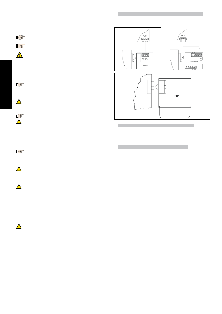
4. ELECTRIC CONNECTIONS
Fig. 2
Fig. 2
* Only if don’t use J4 connector
* Only if don’t use J4 connector
*
C
J4
230 V / 50 Hz
or
115 v / 60Hz
(According to
the selected
control unit)
115 Vac
max 60w
(According to
the selected
control unit)
13
ENGLISH
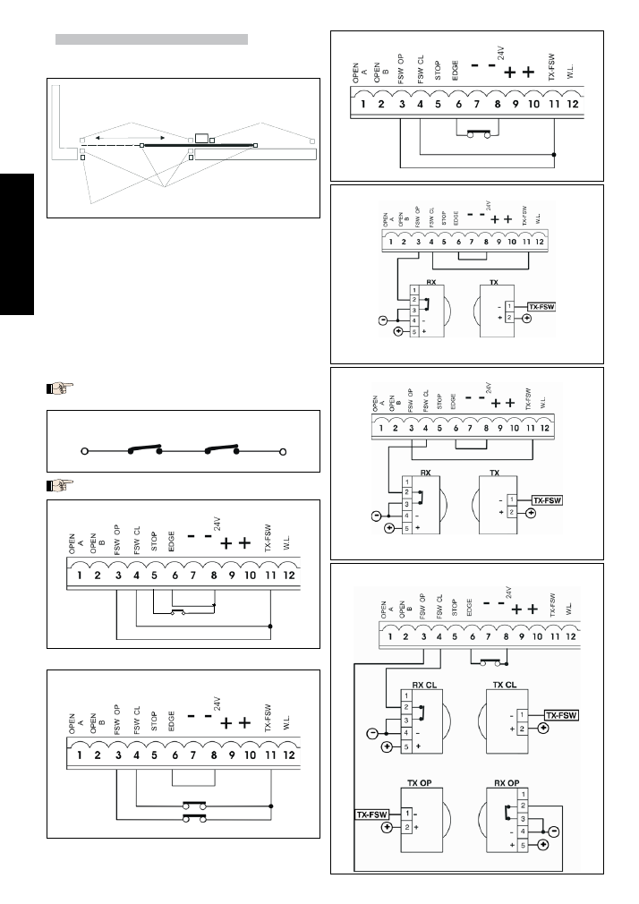
4.1. Connection of photocells and safety devices
Before connecting the photocells (or other devices) we advise you to
select the type of operation according to the movement area they have
to protect (see fig.3):
Opening safety devices:
they operate only during the gate opening
movement and, therefore, they are suitable for protecting the area
between the opening leaf and fixed obstacles (walls, etc) against the
risk of impact and crushing.
Closing safety devices:
they operate only during the gate closing mo-
vement and, therefore, they are suitable for protecting the closing area
against the risk of impact.
Opening/closing safety devices:
they operate during the gate opening
and closing movements and, therefore, they are suitable for protecting
the opening and closing areas against the risk of impact.
“Edge” safety devices:
they operate during the gate opening and closing
movements and, therefore, they are suitable for protecting the areas
between the moving leaf and fixed obstacles (pillars, walls, etc) against
the risk of shearing and dragging.
Encoder (optional):
operates during the gate opening and closing move-
ments and, therefore, it is suitable for protecting the opening and closing
area against the risk of impact, crushing, shearing and dragging.
If two or more safety devices have the same function (opening, closing,
opening and closing, edge), the contacts must be connected to each
other in series (fig. 4). N.C. contacts must be used.
If safety devices are not used, jumper connect the terminals as shown in
fig. 5.
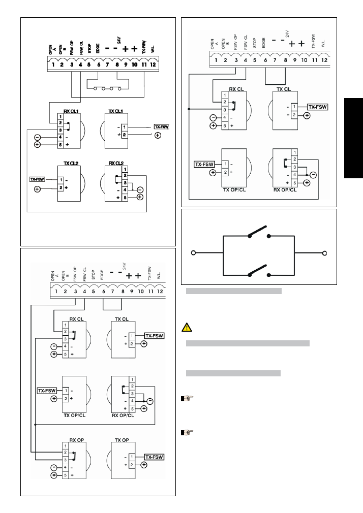
The most common photocell and safety device lay-outs are shown below
(from fig. 6 to fig. 13).
•
•
•
•
•
Fig. 3
Fig. 3
Fig. 4
Fig. 4
Connection of two N.C. contacts in series
(e.g. Photocells, Stop, Edge, etc.)
Connection of two N.C. contacts in series
(e.g. Photocells, Stop, Edge, etc.)
Fig. 5
Fig. 5
Connection of no safety device
Connection of no safety device
Fig. 6
Fig. 6
Connection of a closing safety device and an opening safety device
Connection of a closing safety device and an opening safety device
Fig. 7
Fig. 7
Connection of an “edge” safety device
Connection of an “edge” safety device
Fig. 8
Fig. 8
Connection of a pair of photocells for opening
Connection of a pair of photocells for opening
Fig. 9
Fig. 9
Connection of a pair of closing photocells
Connection of a pair of closing photocells
Fig. 10
Fig. 10
Connection of a pair of opening photocells, a pair of closing photocell
and an edge safety device
Connection of a pair of opening photocells, a pair of closing photocell
and an edge safety device
Closing
photocells
Closing photocells
Opening or
opening/closing
photocells
"Edge" safety devices
14
ENGLISH
Fig. 11
Fig. 11
Connection of two pairs of closing photocells and two edge safety
devices
Connection of two pairs of closing photocells and two edge safety
devices
Fig. 12
Fig. 12
Connection of a pair of closing photocells, a pair of opening photocells
and a pair of opening/closing photocells
Connection of a pair of closing photocells, a pair of opening photocells
and a pair of opening/closing photocells
4.2. J7 Terminal board - Power supply (fig. 2)
POWER SUPPLY (
TERMINALS
PE-N-L):
PE:
Earth connection
N:
230 V- power supply ( Neutral )
L:
230 V- power supply ( Line )
For correct operation, the board must be connected to the earth conductor
in the system. Install an adequate differential thermal breaker upstream
of the system.
4.3. J6 Terminal board - Motors and flashing lamp (fig. 2)
MOTOR - (terminals 13-14-15):
Motor connection. In gearmotors with
a built-in control unit, this connection is pre-wired standard. PFor leaf
opening direction, see basic programming in Chpt 5.1.
LAMP - (terminals 16 -17):
Flashing lamp output ( 230 V -)
4.4. J1 Terminal board - Accessories (fig. 2)
OPEN A - “Total Opening” command (terminal 1):
any pulse generator
(push-button, detector, etc.) which, by closing a contact, commands
total opening and/or closing of the gate leaf.
To install several total opening pulse generators, connect the N.O. contacts
in parallel (see fig. 14).
OPEN B - “Partial opening “ or “Closing” command (terminal 2):
any
pulse generator (push-button, detector, etc.) which, by closing a
contact, commands partial opening and/or closing of the gate leaf.
In the B and C logics, it always commands gate closure.
To install several partial opening pulse generators, connect the N.O.
contacts in parallel (see fig. 14).
•
•
•
•
•
•
•
Fig. 13
Fig. 13
Connection of a pair of closing photocells and a pair of
opening/closing photocells
Connection of a pair of closing photocells and a pair of
opening/closing photocells
Fig. 14
Fig. 14
Connection of two N.O. contacts in parallel
(e.g. Open A, Open B)
Connection of two N.O. contacts in parallel
(e.g. Open A, Open B)
15
ENGLISH
FSW OP - Opening safety devices contact (terminal 3):
The purpose
of the opening safety devices is to protect the leaf movement area
during opening. During opening, in the A-AP-S-E-EP logics the safety
devices reverse the movement of the gate leaves, or stop and restart
the movement when they are released (see advanced programming
in Chpt 5.2). During the opening cycle in logics B and C, they interrupt
movement. They never operate during the closing cycle.
If the Opening safety devices are engaged when the gate is closed, they
prevent the leaf opening movement.
To install several safety devices, connect the N.C. contacts in series
(fig.4).
If no opening safety devices are connected, jumper connect inputs OP and
-TX FSW (fig. 5).
FSW CL - Closing safety devices contact (terminal 4):
The purpose of the
closing safety devices is to protect the leaf movement area during
closing. During closing, in the A-AP-S-E-EP logics, the safety devices
reverse the movement of the gate leaves, or stop and reverse the
movement when they are released (see advanced programming
in Chpt 5.2). During the closing cycle in logics B and C, they interrupt
movement. They never operate during the opening cycle.
If the Closing safety devices are engaged when the gate is open, they
prevent the leaf closing movement.
To install several safety devices, connect the N.C. contacts in series
(fig.4).
If no closing safety devices are connected, jumper connect terminals CL
and -TX FSW (fig. 5).
STOP - STOP contact (terminal 5):
any device (e.g. a push-button)
which, by opening a contact, is able to stop gate movement.
To install several STOP devices, connect the N.C. contacts in series.
If STOP devices are not connected, jumper connect the STP and - termi-
nals.
EDGE - EDGE safety device contact (terminal 6):
The purpose of the
“edge” safety device is to protect the leaf movement area during
opening/closing against fixed obstacles (pillars, walls, etc.). In all
logics, during opening and closing, the safety devices reverse gate
leaf movement for 2 seconds. If the safety devices operate again
during the 2-seconds reversing time, they STOP movement without
any reversing.
If the Edge safety devices are engaged while the gate is closed or open,
they prevent the leaves movement.
To install several safety devices, connect the N.C. contacts in series
(fig.4).
If edge safety devices are not connected, jumper connect the EDGE and
- inputs. (fig. 5).
- Negative for power supply to accessories (terminals 7 and 8)
+ 24 Vdc - Positive for power supply to accessories (terminals 9 and
10)
Accessories max. load is 500 mA. To calculate absorption values, refer to
the instructions for individual accessories.
TX -FSW - Negative for power supply to photocell transmitters (terminal 11)
If you use this terminal for connecting the negative for supplying
power to the photocell transmitters, you may, if necessary, also use
the FAIL SAFE function (see advanced programming in Chpt 5.2).
If this function is enabled, the equipment checks operation of the
photocells before every opening or closing cycle.
W.L. - Power supply to indicator-light / timed output (terminal 12)
Connect a 24 Vdc - 3 W max indicator-light or timed output, if ne-
cessary, between this terminal and the +24V supply (see advanced
programming in Chpt 5.2).
To avoid geopardising correct operation of the system, do not exceed the
indicated power.
•
•
•
•
•
•
•
•
4.5. Connector J2 - Rapid connection to Minidec, Decoder and RP
This is used for rapid connection of Minidec, Decoder and RP receivers (see
fig. 15, 16 and 17). Connect the accessory, with the components side facing
the inside of the board. Insert and remove after cutting power.
4.6. Connector J6 - Limit-switches rapid connection (fig.2)
This input is intended for rapid connection of the opening and closing
limit-switches designed to stop the leaf, or for start of decelerations or for
braking (see advanced programming in Chpt. 5.2.). In gearmotors with a
built-in control unit, this connection is pre-wired as standard (fig. 2). For leaf
opening direction, see advanced programming in Chpt 5.2.
4.7. Connector J3 - Encoder rapid connection (fig.2)
This input is designed for rapid connection of the Encoder (optional). To fit
the encoder on the motor, refer to the relevant instructions.
The presence of the encoder is signalled - when the gearmotor is running
- by the flashing of the “Encoder” LED on the board.
When the encoder is used, the control unit knows the exact position of the
gate while it is moving.
The encoder controls the adjustments of some of the control unit’s func-
tions in a different way (partial opening or deceleration - see advanced
programming in Chpt 5.2) and as an anti-crushing device.
If the gate strikes an obstacle during opening or closing, the encoder im-
mediately reverses the gate leaf for 2 seconds. If the encoder operates
again during the 2-seconds reversing time, it STOPS movement without
commanding any reversing.
Fig. 15
Fig. 15
Fig. 16
Fig. 16
Fig. 17
Fig. 17
16
ENGLISH
5. PROGRAMMING
To program operation of the automated system, you have to access the
“PROGRAMMING” mode.
Programming is split into two parts: BASIC and ADVANCED.
5.1. BASIC PROGRAMMING
To access BASIC PROGRAMMING, press key
F
:
if you press it (and hold it down), the display shows the name of the first
function.
if you release the key, the display shows the value of the function that can
be modified with keys
+
and
-
.
if you press
F
again (and hold it down), the display shows the name of
the next function, etc.
when you reach the last function, press
F
to exit the program, and the
display resumes showing the gate status.
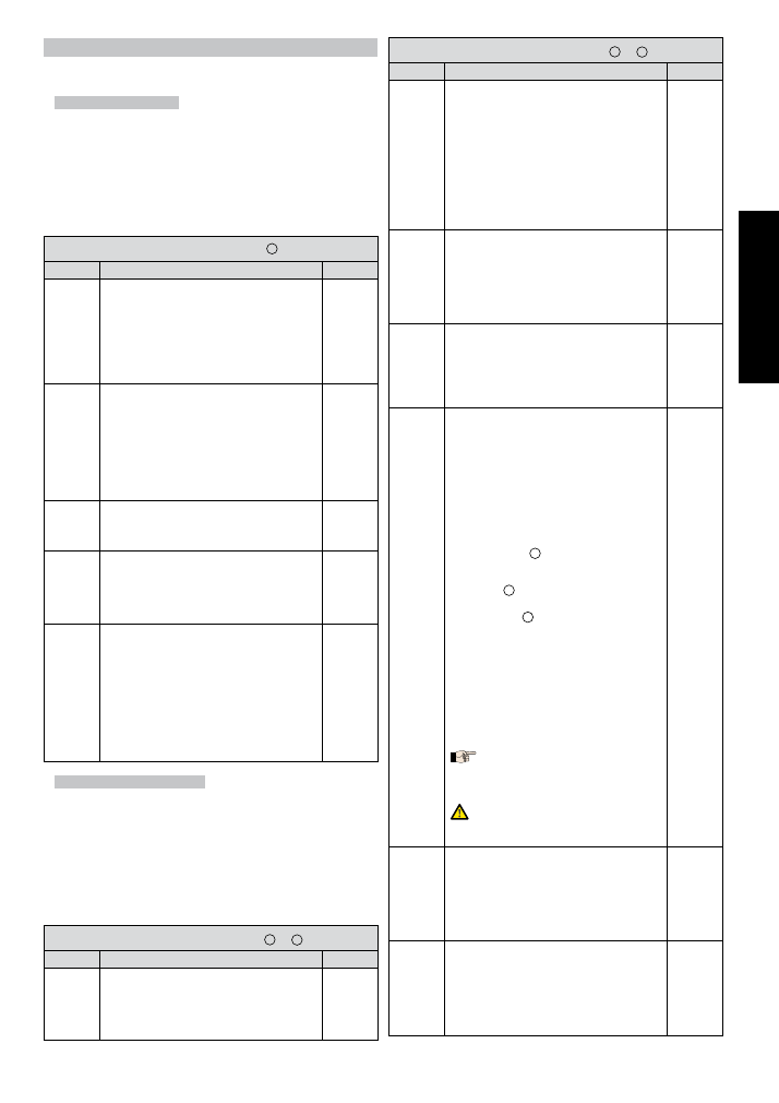
The following table shows the sequence of functions accessible in BASIC
PROGRAMMING:
BASIC PROGRAMMING
F
Display
Function
Default
LO
FUNCTION LOGICS (see tab. 3/a - h):
A
=Automatic
AP
=“Stepped” automatic
S
= “Safety” Automatic
E
= Semi-automatic
EP
= “Stepped” Semi-automatic
C
= Dead-man
b
= “B” Semi-automatic
bC
= Mixed Log. (
b
opening /
C
closing)
EP
PA
PAUSE TIME:
This has effect only if the automatic logic was
selected. Adjustable from
0
to
59
sec. in one-
second steps.
Subsequently, display changes to minutes and
tens of seconds (separated by a point) and time
is adjusted in 10-second steps, up to the maximum
value of
4.1
minutes.
E.g. if the display shows
2.5
, pause time is 2 min.
and 50 sec.
2.0
F0
FORCE:
Adjusts Motor thrust.
01
= minimum force
50
= maximum force
50
d1
OPENING DIRECTION:
Indicates the gate opening movement and
makes it possible not to change the motor and
limit-switch connections on the terminal board.
-3
= Right-hand opening movement
E-
= Left-hand opening movement
-3
St
GATE STATUS:
Exit from programming and return to gate status
viewing.
00
= Closed
01
= Now opening
02
= Stopped
03
= Open
04
= Pause
05
= “FAIL SAFE” tripped (chpt. 5.2)
06
= Now closing
07
= Now reversing
08
= Photocells tripped
5.2. ADVANCED PROGRAMMING
To access ADVANCED PROGRAMMING, press key
F
and, as you hold it
down, press key
+
:
if you release key
+
, the display indicates the name of the first function.
if you release key F too, the display shows the value of the function that
can be modified with keys
+
and
-
.
if you press key
F
(and hold it down), the display shows the name of the
next function, and if you release it, the value that can be modified with
keys
+
and
-
is shown.
when you reach the last function, press
F
to exit the program, and the
display resumes showing the gate status.
The following table shows the sequence of functions accessible in ADVAN-
CED PROGRAMMING:
ADVANCED PROGRAMMING
F +
+
Display
Function
Default
b0
MAXIMUM TORQUE AT INITIAL THRUST:
The motor operate at maximum torque (ignoring
the torque setting) at start of movement. Useful
for heavy leaves.
Y
= Active
no
= Disabled
Y
•
•
•
•
•
•
•
•
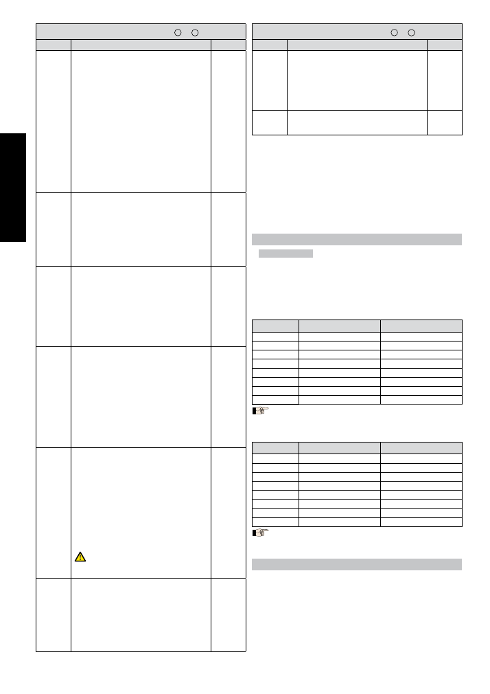
ADVANCED PROGRAMMING
F +
+
Display
Function
Default
br
FINAL BRAKING:
When the gate engages the opening or closing
limit-switch, a braking stroke can be selected
to ensure the leaf is stopped immediately. If
decelerations are selected, braking starts when
they finish.
At
00
value, braking is disabled.
Time can be adjusted from
01
to
20
sec. in 0.1-
second steps.
E.g. if the display indicates
10
, braking time is 1
second.
00
= Braking disabled
from
01
to
20
= Timed braking
05
FS
FAIL SAFE:
If this function is activated, it enables a function
test of the photocells before any gate movement.
If the test fails (photocells not serviceable signal-
led by value
05
on the display), the gate does
not start moving.
Y
= Active
no
= Disabled
no
PF
PRE-FLASHING (5 s):
Activates the flashing lamp for 5 seconds before
start of movement.
no
= Disabled
oP
= Only before opening
CL
= Only before closing
OC
= Before every movement
no
SP
INDICATOR-LIGHT:
If
00
is selected, the output functions as a stan-
dard indicator-light (lighted at opening and
pause, flashing at closing, and off when gate
closed).
Courtesy light:
Different figures correspond to ti-
med activation of the output, which can be used
(by a relay) to power a courtesy lamp. Time can
be adjusted from
0
to
59
sec. in 1-second steps,
and from
1.0
to
4.1
min. in 10-second steps.
Electric lock command and ‘traffic lights’ fun-
ctions:
If you press key
-
from the
00
setting, the
command for the
E1
closing electric lock is
activated;
If you press
-
again, the command for the
E2
closing and opening electric lock is set;
if you press the
-
key again, you can set the
‘traffic lights’ functions
E3
and
E4
.
00
= Standard indicator-light
from
01
to
4.1
= Timed output.
E1
= electric lock command before opening
movement
E2
= electric lock command before opening and
closing movements
E3
= ‘traffic lights’ function: the output is active
in “open” and “open on pause” status and is
disabled 3 seconds before the closing manoe-
uvre starts.
there is 3 seconds of pre-flashing before the
closing manoeuvre.
E4
= ‘traffic lights’ function: the output is active
only in “closed” status.
Do not exceed the output’s maximum load
(24Vdc-3W). If necessary, use a relay
and a power supply source outside the
equipment.
00
Ph
CLOSING PHOTOCELLS LOGIC:
Select the tripping mode of the closing photo-
cells.
They operate for the closing movement only: they
stop movement and reverse it when they are
released, or they reverse it immediately.
Y
= Reverse on release
no
= Reverse immediately when opening
no
oP
OPENING PHOTOCELLS LOGIC:
Select the tripping mode of the opening pho-
tocells.
They operate for the opening movement only:
they stop the movement and restart it when they
are released, or they reverse it immediately.
Y
= Reverse immediately when closing
no
= Restart movement on release
no
17
ENGLISH
ADVANCED PROGRAMMING
F +
+
Display
Function
Default
EC
ENCODER:
If the encoder is used, you may select its pre-
sence.
If the encoder is present and enabled, “decele-
rations” and “partial opening” are controlled by
the encoder (see relevant paragraphs).
The encoder operates as an anti-crushing device:
If the gate strikes an obstacle during opening or
closing, the encoder immediately reverses gate
leaf movement for 2 seconds. If the encoder ope-
rates again during the 2-seconds reversing time,
it stops movement (STOP) without commanding
any reversing. If no sensor is supplied, the para-
meter must be set on
00
. If there is the encoder,
adjust the sensitivity of the anti-crushing system,
by varying the parameter between
01
(maximum
sensitivity) and
99
(minimum sensitivity).
From
01
to
99
= Encoder active and sensitivity
adjustment
00
= Encoder disabled
00
rP
Pre-limit switch DECELERATION:
You can select gate deceleration before the
opening and closing limit-switches have been
tripped.
Time can be adjusted from
00
to
99
.
If an encoder is used, the adjustment is not deter-
mined by time but by motor revs, thus obtaining
greater deceleration precision.
00
= Deceleration disabled
from
01
to
99
= Deceleration enabled
00
rA
Post-limit switch DECELERATIONS:
You can select gate deceleration after the
opening and closing limit-switches have been
tripped.
Time can be adjusted from
00
to
20
sec. in 0.04-
second steps.
If an encoder (optional) is used, the adjustment
is not determined by time but by motor revs, thus
obtaining greater deceleration precision.
00
= Deceleration disabled
from
01
to
20
= Deceleration enabled
05
PO
PARTIAL OPENING:
You can adjust the width of leaf partial ope-
ning.
Time can be adjusted from
01
to
20
sec. in 0.1-
second steps.
If an encoder (optional) is used, the adjustment
is not determined by time but by motor revs, thus
obtaining greater precision of partial opening.
E.g.
for a gate with a sliding speed of 10 m /min,
value
10
corresponds to about 1.7 metres of
opening.
E.g.
for a gate with a sliding speed of 12 m
/min, value
10
corresponds to about 2 metres
of opening.
05
t
WORK TIME:
We advise you to set a value of 5 to 10 seconds
over the time taken by the gate to travel from the
closing limit-switch to the opening limit-switch and
vice versa. This will protect the motor against any
overheating if a limit-switch fails.
Adjustable from
0
to
59
sec. sec. in one-second
steps.
Subsequently, viewing changes to minutes and
tens of seconds (separated by a point) and time
is adjusted in 10 second steps, up to a maximum
value of
4.1
minutes.
E.g.
if the display shows
2.5
, work time is 2 min.
and 50 sec.
the set value does not exactly match the mo-
tor’s maximum operating time, because
the latter is modified according to the
performed deceleration spaces.
4.1
AS
ASSISTANCE REQUEST (combined with next fun-
ction):
If activated, at the end of countdown (settable
with the next function i.e. “Cycle programming”)
it effects 2 sec. of pre-flashing (in addition to the
value already set with the PF function) at every
Open pulse (job request). Can be useful for setting
scheduled maintenance jobs.
Y
= Active
no
= Disabled
no
ADVANCED PROGRAMMING
F +
+
Display
Function
Default
nc
CYCLE PROGRAMMING:
For setting countdown of system operation cycles.
Settable (in thousands) from
00
to
99
thousand
cycles.
The displayed value is updated as cycles pro-
ceed.
This function can be used to check use of the
board or to exploit the “Assistance request”.
00
St
GATE STATUS:
Exit from programming and return to gate status
viewing (see Chpt 5.1.).
6. START-UP
6.1. INPUTS CHECK
The table below shows the status of the LEDs in relation to to the status of
the inputs.
Note the following:
Led lighted
= closed contact
Led off
= open contact
Check the status of the LEDs as per Table.
Operation of the signalling status LEDs
d1 = -3
= Right-hand opening movement
LEDS
LIGHTED
OFF
FCA
Limit-switch free
Limit-switch engaged
FCC
Limit-switch free
Limit-switch engaged
OPEN B
Command activated
Command inactive
OPEN A
Command activated
Command inactive
FSW OP
Safety devices disengaged
Safety devices engaged
FSW CL
Safety devices disengaged
Safety devices engaged
STOP
Command inactive
Command activated
EDGE
Safety devices disengaged
Safety devices engaged
The status of the LEDs while the gate is closed at rest are shown in
bold.
d1 = E-
= Left-hand opening movement
LEDS
LIGHTED
OFF
FCA
Limit-switch free
Limit-switch engaged
FCC
Limit-switch free
Limit-switch engaged
OPEN B
Command activated
Command inactive
OPEN A
Command activated
Command inactive
FSW OP
Safety devices disengaged
Safety devices engaged
FSW CL
Safety devices disengaged
Safety devices engaged
STOP
Command inactive
Command activated
EDGE
Safety devices disengaged
Safety devices engaged
The status of the LEDs while the gate is closed at rest are shown in
bold
7. AUTOMATED SYSTEM TEST
When you have finished programming, check if the system is operating
correctly.
Most important of all, check if the force is adequately adjusted and if the
safety devices are operating correctly.
Note 1
:
to reset the programming default settings, check if the edge
input is opened (SAFE LED OFF), and simultaneously press keys
+,
-
and
F
, holding them down for 5 seconds.
Note 2:
modification of programming parameters comes into effect
immediately, whereas definitive memory storage occurs only
when you exit programming and return to gate status viewing. If
the equipment is powered down before return to status viewing,
all modifications will be lost.
18
ENGLISH
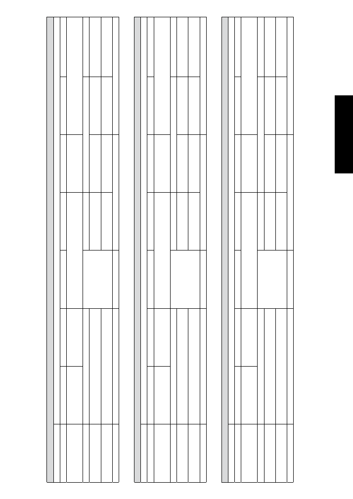
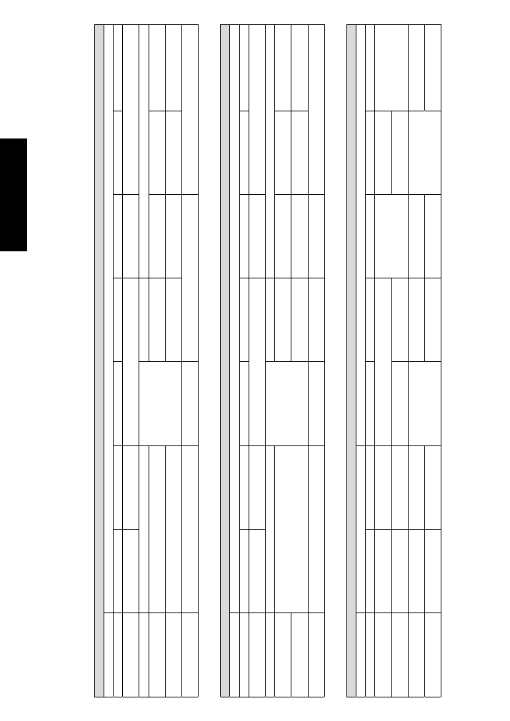
Tab.
3/a
LOGIC
”A
”
PULSES
G
A
TE
ST
A
TUS
OPEN-
A
OPEN-B
STOP
OPENING
SAFETY
DEVICES
C
LOSING
SAFETY
DEVICES
OP/CL
OS.
SAFETY
DEVICE
EDGE
SAFETY
DEVICE
CL
OSED
Opens the leaf and closes it
after pause time
/
Opens leaf for the partial opening time and closes
after pause time
/
No effect (OPEN disabled)
No effect
No effect (OPEN disabled)
OPEN
on
PA
USE
Reloads pause time
/
Stops operation
No effect
Reloads pause time
/
(OPEN disabled)
No effect (OPEN disabled)
ON
CL
OSING
Re-opens the leaf immediately
/
No effect (saves OPEN)
see paragraph 5.2.
Stops and, on r
elease,
re
verses on opening
Re
verses on opening for 2”
0
ON
OPENING
No effect
/
see paragraph 5.2.
No effect
Stops and, on r
elease,
continues opening
Re
verses on closing for 2”
0
STOPPED
Closes the leaf
No effect (OPEN disabled)
No effect
No effect (OPEN disabled)
Tab.
3/b
LOGIC
“AP”
PULSES
G
A
TE
ST
A
TUS
OPEN-
A
OPEN-B
STOP
OPENING
SAFETY
DEVICES
C
LOSING
SAFETY
DEVICES
OP/CL
OS.
SAFETY
DEVICE
EDGE
SAFETY
DEVICE
CL
OSED
Opens the leaf and closes it
after pause time
/
Opens leaf for the partial opening time and closes
after pause time
/
No effect (OPEN disabled)
No effect
No effect (OPEN disabled)
OPEN
on
PA
USE
Re-closes the leaf immediately
Stops operation
No effect
Reloads pause time
/
(OPEN disabled)
No effect (OPEN disabled)
ON
CL
OSING
Re-opens the leaf immediately
/
No effect (saves OPEN)
see paragraph 5.2.
Stops and, on r
elease,
re
verses on opening
Re
verses on opening for 2”
0
ON
OPENING
Stops operation
see paragraph 5.2.
No effect
Stops and, on r
elease,
continues opening
Re
verses on closing for 2”
0
STOPPED
Closes the leaf
No effect (OPEN disabled)
No effect
No effect (OPEN disabled)
Tab.
3/c
LOGIC
”S”
PULSES
G
A
TE
ST
A
TUS
OPEN-
A
OPEN-B
STOP
OPENING
SAFETY
DEVICES
C
LOSING
SAFETY
DEVICES
OP/CL
OS.
SAFETY
DEVICE
EDGE
SAFETY
DEVICE
CL
OSED
Opens leaves and closes
them after pause time
Opens leaf for the partial opening time and closes
after pause time
/
No effect (OPEN disabled)
No effect
No effect (OPEN disabled)
OPEN
on
PA
USE
Re-closes the leaf immediately
Stops operation
No effect
Closes after 5” (OPEN disabled)
No effect (OPEN disabled)
ON
CL
OSING
Re-opens the leaf immediately
No effect (saves OPEN)
see paragraph 5.2.
Stops and, on r
elease,
re
verses on opening
Re
verses on opening for 2”
0
ON
OPENING
Re-closes the leaf immediately
see paragraph 5.2.
No effect
Stops and, on r
elease,
continues opening
Re
verses on closing for 2”
0
STOPPED
Closes the leaf
No effect (OPEN disabled)
No effect
No effect (OPEN disabled)
19
ENGLISH
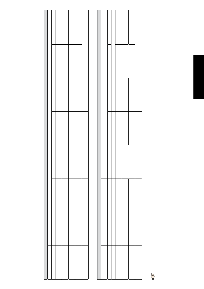
Tab.
3/d
LOGIC
“E”
PULSES
G
A
TE
ST
A
TUS
OPEN-
A
OPEN-B
STOP
OPENING
SAFETY
DEVICES
C
LOSING
SAFETY
DEVICES
OP/CL
OS.
SAFETY
DEVICE
EDGE
SAFETY
DEVICE
CL
OSED
Opens the leaf
Opens the leaf for partial
opening time
No effect (OPEN disabled)
No effect
No effect (OPEN disabled)
OPEN
Re-closes the leaf immediately
Stops operation
No effect
No effect (OPEN disabled)
ON
CL
OSING
Re-opens the leaf immediately
No effect (saves OPEN)
see paragraph 5.2.
Stops and, on r
elease,
re
verses on opening
Re
verses on opening for 2”
0
ON
OPENING
Stops operation
see paragraph 5.2.
No effect
Stops and, on r
elease,
continues opening
Re
verses on closing for 2”
0
STOPPED
Closes the leaf (with the Closing safety devices enga-
ged, it opens at the 2
nd
pulse)
No effect (OPEN disabled)
No effect
No effect (OPEN disabled)
Tab.
3/e
LOGIC
“”EP””
PULSES
G
A
TE
ST
A
TUS
OPEN-
A
OPEN-B
STOP
OPENING
SAFETY
DEVICES
C
LOSING
SAFETY
DEVICES
OP/CL
OS.
SAFETY
DEVICE
EDGE
SAFETY
DEVICE
CL
OSED
Opens the leaf
Opens the leaf for partial
opening time
No effect (OPEN disabled)
No effect
No effect (OPEN disabled)
OPEN
Re-closes the leaf immediately
Stops operation
No effect
No effect (OPEN disabled)
ON
CL
OSING
Stops operation
No effect (saves OPEN)
see paragraph 5.2.
Stops and, on r
elease,
re
verses on opening
Re
verses on opening for 2”
0
ON
OPENING
see paragraph 5.2.
No effect
Stops and, on r
elease,
continues opening
Re
verses on closing for 2”
0
STOPPED
Restarts movement in r
e
verse dir
ection (always closes
after a Stop)
No effect (OPEN disabled)
No effect (if it must open
, it
disables OPEN)
No effect (if it must close, it
disables OPEN)
No effect (OPEN disabled)
Tab.
3/f
LOGIC
“C
”
CONTROLS
AL
W
A
YS
HELD
DOWN
PULSES
G
A
TE
ST
A
TUS
OPEN-
A
(opening)
OPEN-B
(closing)
STOP
OPENING
SAFETY
DEVICES
C
LOSING
SAFETY
DEVICES
OP/CL
OS.
SAFETY
DEVICE
EDGE
SAFETY
DEVICE
CL
OSED
Opens the leaf
No effect
No effect (OPEN-
A
disabled)
No effect (OPEN-B disa-
bled)
No effect (OPEN-
A
disa-
bled)
No effect (OPEN-
A
/B disa-
bled)
OPEN
No effect
Closes the leaf
No effect (OPEN-B disa-
bled)
No effect (OPEN-
A
disa-
bled)
No effect (OPEN-B disa-
bled)
ON
CL
OSING
Stops operation
Stops operation
No effect
Stops operation (OPEN-B
disabled)
Stops operation (OPEN-
A
/B
disabled)
Re
verses on opening for 2”
0
ON
OPENING
Stops operation
Stops operation (OPEN-
A
disabled)
No effect
Re
verses on closing for 2”
0
20
ENGLISH
Tab.
3/g
LOGIC
”B
”
PULSES
G
A
TE
ST
A
TUS
OPEN-
A
(opening)
OPEN-B
(closing)
STOP
OPENING
SAFETY
DEVICES
C
LOSING
SAFETY
DEVICES
OP/CL
OS.
SAFETY
DEVICE
EDGE
SAFETY
DEVICE
CL
OSED
Opens the leaf
No effect
No effect (OPEN-
A
disabled)
No effect (OPEN-B disa-
bled)
No effect (OPEN-
A
disa-
bled)
No effect (OPEN-
A
/B disa-
bled)
OPEN
No effect
Closes the leaf
No effect (OPEN-B disa-
bled)
No effect (OPEN-
A
disa-
bled)
No effect (OPEN-B disa-
bled)
ON
CL
OSING
Re
verses on opening
No effect
Stops operation
No effect
Stops operation (OPEN-B
disabled)
Stops operation (OPEN-
A
/B
disabled)
Re
verses on opening for 2”
0
ON
OPENING
No effect
Stops operation (OPEN-
A
disabled)
No effect
Re
verses on closing for 2”
0
STOPPED
Opens the leaf
Closes the leaf
No effect (OPEN-
A
/B
disabled)
No effect (OPEN-
A
disa-
bled)
No effect (OPEN disabled)
No effect (OPEN-
A
/B disabled)
Tab.
3/h
LOGIC
“BC
”
OPENING
PULSES
/
CL
OSING
COMMANDS
A
LW
A
Y
S
PRESSED
PULSES
G
A
TE
ST
A
TUS
OPEN-
A
(opening)
OPEN-B
(closing)
STOP
OPENING
SAFETY
DEVICES
C
LOSING
SAFETY
DEVICES
OP/CL
OS.
SAFETY
DEVICE
EDGE
SAFETY
DEVICE
CL
OSED
Opens the leaf
No effect
No effect (OPEN-
A
disabled)
No effect
No effect (OPEN-
A
disabled)
OPEN
No effect
Closes the leaf
No effect (OPEN-B disa-
bled)
No effect
No effect (OPEN-B disabled)
No effect (OPEN-
A
/B disa-
bled)
ON
CL
OSING
Re
verses to open
No effect
Stops operation
No effect (saves OPEN A)
Stops operation (OPEN-B
disabled)
Stops operation (OPEN-
A
/B
disabled)
Re
verses to open for 2”
0
ON
OPENING
No effect
Stops operation (OPEN-
A
disabled)
No effect
Re
verses to close for 2”
0
STOPPED
Opens the leaf
Closes the leaf
No effect (OPEN-
A
/B
disabled)
No effect (OPEN-
A
disa-
bled)
No effect (OPEN-B disa-
bled)
No effect (OPEN-
A
/B disabled)
/
If maintained, it pr
olongs the pause until disabled by the command (timer function)
0
If a new pulse occurs within 2 seconds after r
e
versing, it immediately stops operation
.
Effects on other active pulse inputs in brack
ets
.
• •