Full Text Searchable PDF User Manual

AMF 3.1/EN/K.K./01
K
O
AMF 3.1
User Manual

2/22
AMF 3.1 USER MANUAL
Table of Contents
General Descriptions ............................................................................................................................................................................... 3
Connection Diagram ............................................................................................................................................................................... 4
Front Panel .............................................................................................................................................................................................. 5
Rear Panel ............................................................................................................................................................................................... 9
Terminal Connections ......................................................................................................................................................................... 9
Alarm Codes & Descriptions ................................................................................................................................................................ 11
Interface Structure ................................................................................................................................................................................. 14
MENU SCREEN STRUCTURE ........................................................................................................................................................... 16
P2-Alarm Log Screen ........................................................................................................................................................................ 18
P3-Maintenance Timers Screen ......................................................................................................................................................... 18
Digital Input Functions & Descriptions ................................................................................................................................................ 19
Digital Output Functions & Descriptions .............................................................................................................................................. 21
Document Version................................................................................................................................................................................. 22

3/22
AMF 3.1 USER MANUAL
General Descriptions
AMF 3.1 is a microprocessor-based controller, which monitors single or 3 phase Mains voltage, transfers
the load between the Mains and the Generator and checks for system failures. The unit eliminates the need of
common panel indicators, hence reduces the cost of the Generator panel. AMF 3.1 has 3 operation modes, which
are Automatic, Test and Off modes. The desired operation mode can be set via the buttons located on the front
panel. By pressing the Menu button for 3 seconds, the user can edit and save any parameter among the 425
parameters in the unit. This feature allows AMF 3.1 to be easily adapted to any engine without the need of a
separate unit.
Functions
Automatic engine start and stop
Start the Generator and transfer the load in the case of a Mains failure
True RMS voltage and current measurement
Sensing Generator failures
Automatic load transfer
Pre-heat function
Automatic, Test and Off operation modes
Measurement instruments which reduce the panel cost
Time stamped log of the last 15 failures
Record of engine running hours and indicate when maintenance is needed
Manual control of the MCB and GCB during Test mode
Ability to connect analog oil pressure and water temperature probes
Screen saver mode which preserves power
Comprehensive parameter menu where all the system limits, timers and operation modes can be viewed
and edited
Monitoring and parameter setting via communication port
Ability to update the microprocessor software via communication port
Inputs & Outputs
3 phase Mains and Generator voltage inputs
1 phase alternator current input
12V or 24V power supply
Oil pressure and water temperature analog
inputs
Charge fail input
Crank relay output
Fuel solenoid relay output
Generator contactor relay output
Mains contactor relay output
3 Programmable Aux. Relay Outputs
6 Programmable Aux. Relay Inputs
Failures
Crank and Stop Failure
Over/Under Speed Failure
Over/Under Voltage Failure
Overcurrent Failure
Battery Over/Under Voltage Failure
Engine Overheat Failure
Charge Failure
Low Oil Pressure Failure
Service Time
Aux. Failure
4/22
AMF 3.1 USER MANUAL
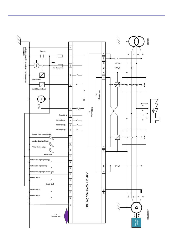
Connection Diagram
7
8
9
5/22
AMF 3.1 USER MANUAL
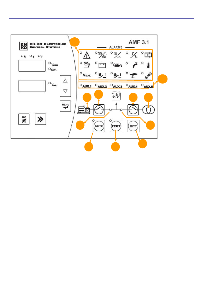
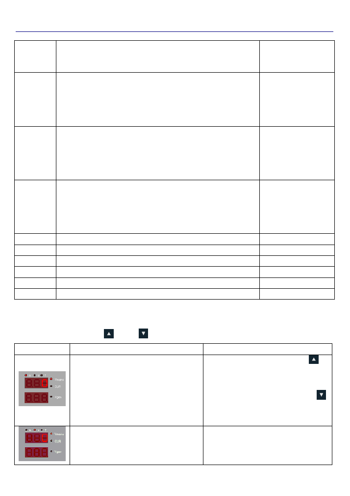
Front Panel
Generator Status LED (1):
Generator idle when the LED is off.
Generator running when the LED is on
The LED will be blinking during the failure delay time during Generator initial cranking and cool-down and
stop delay timers during Generator stopping. These timers will be explained below.
Generator Contactor Status Button (2):
This button is active while in TEST operation mode. This button allows
for the load to be transferred to the Generator after start-up. The contactor is open while the generator is idle. The
status of the contactor is indicated via the LED indicator. If the LED is lit, the contactor is closed and the Load is
fed through the Generator. The Mains contactor must be opened in order to close the Generator contactor.
Generator Contactor Status LED (3):
Indicates the GCB status. If the GCB output (terminals 6 and 7) are closed
the LED will be lit. If the GCB output is open, the LED will be off.
Mains Contactor Status LED (4):
Indicates the MCB status. If the MCB output (terminals 6 and 7) are closed the
LED will be lit. If the MCB output is open, the LED will be off.
Mains Contactor Status Button (5):
This button is active while in TEST operation mode. This button allows for
the load to be transferred to the Mains. The status of the contactor is indicated via the LED indicator. If the LED is
lit, the contactor is closed and the Load is fed through the Mains. The Generator contactor must be opened in
order to close the Mains contactor.
3
2
4
6
1
7
8
9
10
11
5

6/22
AMF 3.1 USER MANUAL
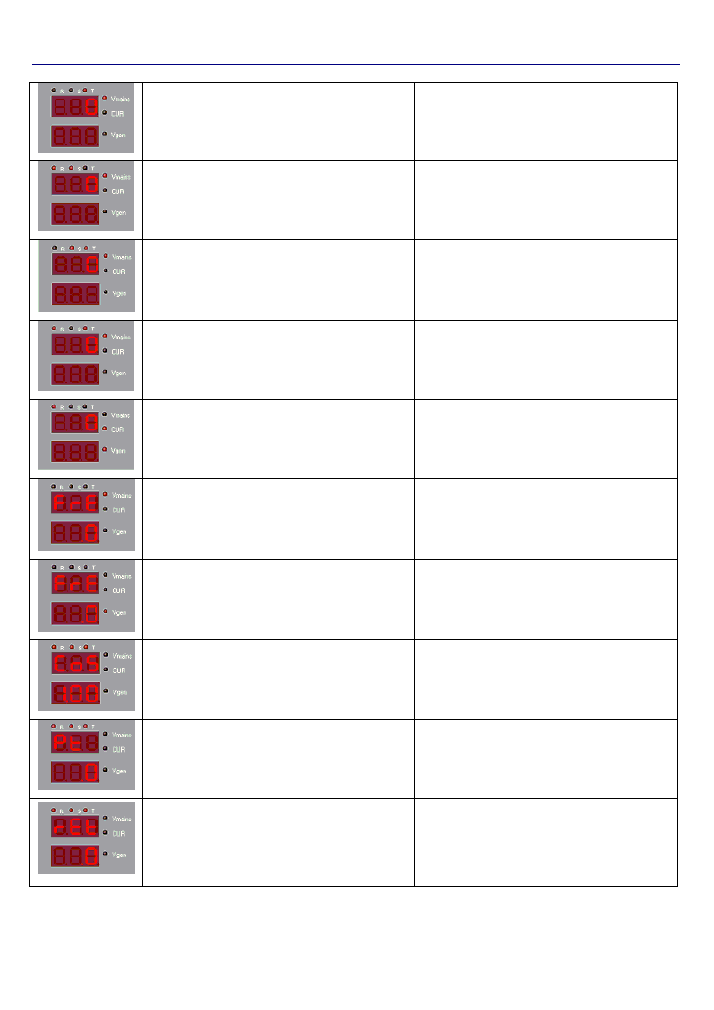
Mains Status LED (6):
When off, the Mains values are outside the limits set by the parameters.
When lit, the Mains values are within the limits set by the parameters.
The LED will be blinking while switching from Mains Normal condition to Mains Failure condition or while
switching from Mains Failure condition to Mains Normal condition which will be exlpained below.
Automatic Operation Mode Button (7):
Pressing this button will put the AMF into Automatic Operation Mode.
While in this mode, in case of a Mains Failure, the Generator will be started automatically and the Load will be
transferred.
Test Operation Mode Button (8):
Pressing this button will put the AMF into Test Operation Mode. While in this
mode, in case of a Mains Failure, the Generator will be started automatically, and the contactors will be controlled
via the Generator and Mains Contactor Buttons.
Off Operation Mode Button (9):
Pressing this button will put the AMF into Off Operation Mode. When this button
is pressed once, the Generator will be cooled-down then stopped. By pressing this button for the second time, the
Generator will be stopped without being cololed-down.
Failure Indicator LED’s (10):
Starting from top left corner, the failures go as Failure Active, Engine Under/Over
RPM, Aternator Under/Over Voltage, Start/Stop, Over Current, Fuel Level, Charge Voltage, Low Oil Pressure,
Coolant Level, Engine Over Heat, Battery Voltage, Mains Contactor, Generator Contactor, Emergency Stop and
Maintenance Time LED’s can be found.
Auxiliary Input LED’s (11):
These LED’s indicate the status of the digital inputs which are assigned to auxiliary
digital inputs.
Display LED’s:
These LED’s can be found on the right hand side of each display.They indiacte that measurement
is being showed on the displays. The info being scrolled using the Up, Down and Menu buttons.
ESC Button:
This button has several functions which are listed below.
While not in the Menu, in case of a failure, by pressing once the alarm horn will be silenced. By pressing
the second time the faiilure will be deleted,
While in the Menu, pressing the button will exit the Menu.
While in the Parameter menu, if the value entered while editing the parameter, pressing this button will exit
without saving.
Menu Button (Enter):
Used to enter the Menu. The button must be pressed for 3 seconds to enter the Menu.
Used to acknowledge any changes made while parameter editing.
Up and Down Arrow Buttons:
buttons have 2 uses.
While in normal operation, the buttons are used to cycle through the Display LED’s. Pressing the Menu
Button will acknowledge the display selection and move on to the next display.
While in parameter menu, after pressing the Enter Button and selecting a parameter to edit, the desired
value can be selected by using the Up and Down Arrow Buttons.
7/22
AMF 3.1 USER MANUAL
Selection Button:
While in normal operation this button has the same function as the button above.
While in parameter menu, after pressing the Enter Button and selecting a parameter to edit, the desired
digit can be selected by using this button, each press will shift the selected digit to the right.
OPERATION MODES
Automatic Operation Modes:
When the Auto Button
is pressed the Generator will enter the Automatic
Operation Mode. In this mode, the 3 phase Mains is constantly monitored against the limits set by the parameter
values shown below.
P036
Mains Under Voltage
P037
Mains Over Voltage
When the Mains is normal, the Load is supplied by the Mains. If the monitored values of the Mains are
outside the limits set by the related parameters and the time period specified by the
“P039 – Mains Failure Delay
Timer” has passed, it means there is a Mains failure. In this case the Mains contactor is opened and the Generator
is started.
Once the Generator has started, the unit will wait for the time period set by the “P018 – General Failure
Delay Timer” and will check for any failures. Then, after waiting for the time period set by “P006 – Generator
Contact Delay Timer”, the Generator contactor will be closed and the Load is transferred to the Generator.
Once the monitored values of the Mains are back and stays within the limits set by the related parameters
for the time
period set by the “P005 – Mains Contact Delay Timer”, the Mains contactor will be closed and the
Load is transferred to the Mains. In the case where the Generator has supplied the Load since the engine started,
the engine will be
cooled down for the time period set by “P007 – Engine Cool-down Timer”. If the Generator has
not supplied the Load since the engine started, the Generator will be stopped without cooling down. In the
Automatic operation mode, if the AMF unit is receiving a signal that the Generator is running although it is not
supposed to, the AMF will try to stop the Generator.
Test Operation Mode:
When the TEST Button is pressed the Generator enters the Test operation mode and the
Generator will start without checking the Mains. In this mode the Generator Contactor Status Button
and the
Mains Contactor Status Button
will become active. If the Generator is running and the Generator Status LED
is constantly lit, the Generator contactor can be checked using the Generator Contactor Status Button
as long
as the Mains contactor is open. The Generator Contactor Status Button
will energize the GCB if it is de-
energized and will transfer the Load to the Generator. If the GCB is already energized, pressing the Generator
Contactor Status Button will idle the Load. The same situation is applicable for the Mains Contactor Status Button
also. If the Mains status LED is constantly lit and the Generator contactor is open, the Load can be transferred to
P040
Mains Under Frequency
P041
Mains Over Frequency

8/22
AMF 3.1 USER MANUAL
the Mains by pressing the Mains Contactor Status Button
. The Load can be idled by pressing the Mains
Contactor Status Button again.
OFF Operation Mode:
When the OFF button is pressed the AMF will stop executing the Generator and Mains
control functions and enter sleep mode.
If the Generator is running:
By pressing the OFF button once, if the Generator has supplied the load once or more times, the
Generator will be cooled-down for the time period set by
“P007 – Engine Cool-down Timer”,
then
completely stopped. If the Load has never been transferred to the Generator then it will be stopped
without being cooled-down
By pressing the OFF button twice, the Generator will be stopped without being cooled-down. The LED
display will write OFF and measurements and displays will be shut-off.
If the Generator is idle (stopped):
By pressing the OFF button once, the Generator enters OFF Operation Mode but the measurements will
continue to be displayed. If the OFF button is pressed for the second time, the LED displays will write OFF
and the measurement displays will turn off. If the user desires to view the measurements while in OFF
Operation Mode the measurement screens can be viewed by pressing the Up
or Down
Arrow
Buttons.
9/22
AMF 3.1 USER MANUAL
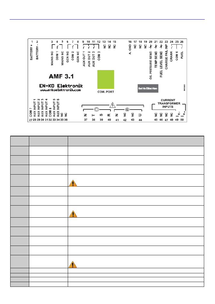
Rear Panel
Terminal Connections
TERMINAL
NO
TERMINAL NAME
DESCRIPTION
1
BATTERY +
The positive terminal of the battery must be connected. The value of the terminal must be
between 9
– 30V.
2
BATTERY -
The negative terminal of the battery must be connected. The negative terminal of the battery
should be grounded.
3
MAINS NO
The dry contact output, which controls the Mains contactor. This output is Normally Open.
(250Vac 10A)
4
COM 1
The common input of Terminals No 3 and No 5 (MCB). (250Vac 10A)
Caution: In order to enable the related Terminals to COM 1, this input must NOT
be left empty.
5
MAINS NC
The dry contact output, which controls the Mains contactor. This output is Normally Closed.
(250Vac 10A)
6
GEN NO
The dry contact output, which controls the Generator contactor. This output is Normally Open.
(250Vac 10A)
7
COM 2
The common input of Terminals No 6 and No 8 (GCB). (250Vac 10A)
Caution: In order to enable the related Terminals to COM 2, this input must NOT
be left empty.
8
GEN NC
The dry contact output, which controls the Generator contactor. This output is Normally
Closed. (250Vac 10A)
9
AUX OUT 1
Functional output. Please refer to parameters P254-P255. (250Vac 6A)
10
AUX OUT 2
Functional output. Please refer to parameters P256-P257. (250Vac 6A)
11
AUX OUT 3
Functional output. Please refer to parameters P258-P259. (250Vac 6A)
12
COM 3
The common output for Terminals No 9, No 10 and No 11.
Caution: In order to enable the related Terminals to COM 3, this input must NOT
be left empty.
13
N/A
Terminal connection is empty, please do not make any connections.
14
N/A
Terminal connection is empty, please do not make any connections.
15
N/A
Terminal connection is empty, please do not make any connections.
16
A. GND
To be connected to Generator chassis for the measurement inputs.
10/22
AMF 3.1 USER MANUAL
17
N/A
Terminal connection is empty, please do not make any connections.
18
N/A
Terminal connection is empty, please do not make any connections.
19
N/A
Terminal connection is empty, please do not make any connections.
20
OIL PRESURE SEND.
Analog oil pressure sender is to be connected to this terminal. The settings related to this
input can be changed via parameters P084-P144.
21
TEMP SEND.
Analog water temperature sender is to be connected to this terminal. The settings related to
this input can be changed via parameters P147-P203.
22
N/A
Terminal connection is empty, please do not make any connections.
23
CHARGE FAIL INP.
Charge alternator excitation winding is connected to this input. The panel excites the charge
alternator by feeding constant current during cranking. This terminal feeds 120mA in 24V
systems and 200mA in 12V systems. Panel marş sırasında sabit akım basarak şarj
a
ltarnatörüne uyartım vermektedir. Bu çıkıştan 24V sistemlerde 120mA, 12V sistemlerde 200
mA akım basılmaktadır
24
CRANK
Crank solenoid is to be connected to this output.
25
COM 6
The common input of Terminals No 24 and No 26.
Caution: In order to enable the related Terminals to COM 6, this input must NOT
be left empty.
26
FUEL
The fuel or stop solenoid is to be connected to this input. The settings related to this input can
be changed via parameters P017 and P028.
27
COM 7
The common input of Terminals No 28, No 29, No 30 and No31. Can be connected to Battery
- or Battery+. Because the digital inputs are bi-directional, when connected to Battery - the
digital inputs are activated on Battery + voltage level and vice versa.
Caution: If a battery connection is NOT made to COM 7 the related digital inputs
will not be operational.
28
AUX INPUT 1
1
st
digital input. Can be configured via parameters P206-P211.
29
AUX INPUT 2
2
nd
digital input. Can be configured via parameters P212-P217.
30
AUX INPUT 3
3
rd
digital input. Can be configured via parameters P218-P223.
31
AUX INPUT 4
4
th
digital input. Can be configured via parameters P224-P229.
32
COM 8
The common input of Terminals No 33, No 34, No 35 and No36. Can be connected to Battery
- or Battery+. Because the digital inputs are bi-directional, when connected to Battery - the
digital inputs are activated on Battery + voltage level and vice versa.
Caution: If a battery connection is NOT made to COM 8 the related digital inputs
will not be operational.
33
AUX INPUT 5
5
th
digital input. Can be configured via parameters P230-P235.
34
AUX INPUT 6
6
th
digital input. Can be configured via parameters P236-P241.
35
N/A
Terminal connection is empty, please do not make any connections.
36
N/A
Terminal connection is empty, please do not make any connections.
37
N
Mains Neutral input
38
T
Mains T Phase input (20-500Vac)
39
S
Mains S Phase input (20-500Vac)
40
R
Mains R Phase input (20-500Vac)
41
N
Alternator Neutral input
42
N/A
Terminal connection is empty, please do not make any connections.
43
N/A
Terminal connection is empty, please do not make any connections.
44
U
Alternator U Phase input (20-500Vac)
45
N/A
Terminal connection is empty, please do not make any connections.
46
N/A
Terminal connection is empty, please do not make any connections.
47
N/A
Terminal connection is empty, please do not make any connections.
48
N/A
Terminal connection is empty, please do not make any connections.
49
IR-
R Phase Current Transformer input - terminal (Max. 5A AC)
50
IR+
R Phase Current Transformer input + terminal (Max. 5A AC)
11/22
AMF 3.1 USER MANUAL
COM PORT
Used for ENKO Pro-Link SCADA PC connection
Important Note
:
For the Low Oil Pressure digital Input, the related activation time must be set a “2”. When this
input is assigned, the check will be made after the engine has started regardless of the failure activation time.
Alarm Codes & Descriptions
ALARM
LEDS
ALARM
CODES
DESCRIPTION
It indicates that there is an alarm in the system. If it flashes, the alarm is still active. If it
is continously lit, the alarm is not active. It is off when the alarm is cleared.
F11
F11 is displayed when there is low/high frequency alarm.
This alarm is active when the alternator frequency value is less than “P065: Generator
Under Frequency” or more than “P066: Generator Over Frequency”,
F10
It indicates there is high/low alternator voltage alarm when the voltage value is less than
or more than the set values (see : P058: Generator Under Voltage, P059: Generator
Over Voltage
F15
It indicates Engine Failed to Start / Stop Alarm.
In automatic mode, after there is mains failure, this alarm is displayed if the engine does
not start after cranking “P002: Crank Attempts“.
Another alarm source is : If one of “Running Feedback signals is still active after AMF
releases fuel valve and attempts to stop the engine.
F24
It indicates “Overcurrent” alarm. This alarm is indicated when the total current is more
than “P272: Over Current Failure Value”.
F22
F23
It indicates “Fuel Level Alarm”. F22 is displayed when it is less than P303: Fuel Under
Level or more than P304: Fuel Over Level. F23 is displayed when it is less than the set
value for P305: Fuel Level Generator Stop Value. (see: P303: Fuel Under Level, P304:
Fuel Over Level, P305: Fuel Level Generator Stop Value).
F18
F55
It
indicates “Charge Voltage Alarm”. F18 is displayed when the charging voltage is less
than or more than the set values (see P079: Charge Alternator Trip Value and P080:
Charge Alternator Warning Value) while the engine is running.
F16
F25
It indicates “Low Oil Pressure Alarm”.
F16 is displayed when the digital input set as Oil Pressure Switch becomes active while
the engine is running.
In case oil pressure sender is used, F25 is displayed when the oil pressure value is less
than “P89: Analog Low Oil Pressure Value” while the engine is running.
F21
It indicates “Low Coolant Level Value Alarm”. F21 is displayed when the digital input set
for Coolant Level Switch becomes active.
F17
F51
It indicates “High Water Temperature Alarm”.
F17 is displayed when the digital input set for Water Temperature Switch becomes
active.
In case Analog Temperature Sensor is used, F51 is displayed when the temperature is
more than “P150: High Temperature (Flexible Sensor) Alarm”.
12/22
AMF 3.1 USER MANUAL
F19
F20
It indicates “Low Battery Voltage Alarm”.
F20 is displayed when the battery voltage is less than or more than the set values. (see:
P47: Battery Voltage Failure Lower Limit, P48: Battery Voltage Failure Upper Limit).
F43
It indicates “Mains Circuit Breaker Feedback Failure Alarm”.
F43 is displayed when the digital input set for MCB Contact Feedback does not become
active after the breaker is energized.
F42
It indicates “Generator Circuit Breaker Feedback Failure Alarm”.
F42 is displayed when the digital input set for GCB Contact Feedback does not become
active after the breaker is energized.
F44
It indicates “Emergency Stop Alarm”. F44 is displayed when the digital input set for
Emergency Stop becomes active.
It indicates “Maintenance Time Passed” alarm.
This LED is lit when “P329: Periodic Engine Maintenance Timer Set Value and “P330:
Periodic Maintenance Timer Value expire.
F31
It indicates “Aux. Failure Input 1 Alarm”.
This alarm is active when the digital input set for External Alarm Input 1 becomes active.
F32
It indicates “Aux. Failure Input 2 Alarm”.
This alarm is active when the digital input set for External Alarm Input 2 becomes active.
F33
It indicates “Aux. Failure Input 3 Alarm”.
This alarm is active when the digital input set for External Alarm Input 3 becomes active.
F34
It indicates “Aux. Failure Input 4 Alarm”.
This alarm is active when the digital input set for External Alarm Input 4 becomes active.
F35
It indicates “Aux. Failure Input 5 Alarm”.
This alarm is active when the digital input set for External Alarm Input 5 becomes active.
F26
It indicates “High KW Alarm”.
This alarm is active when the measured kW value is equal to or more than P277: KW
Failure Value.
F27
It
indicates “High KVA Alarm”.
This alarm is active when the measured kVA value is equal to or more than P292: KVA
Alarm Value.
F28
It indicates “High KVAR Alarm”.
This alarm is active when the measured kVAR value is equal to or more than P282-
KVar Failure Value.
F29
It indicates “Power Factor Alarm”.
This alarm is active when the measured Power Factor value is equal to or more than
P287: Power Factor Failure Value.
F38
It indicates “Seismic Alarm.”
This alarm is active when the digital input set for Earthquake Sensor becomes active.
F46
It indicates “Oil Pressure Sensor Failure Alarm”.
When there is a oil pressure sensor, the reason of the failure may be that the sensor
has failed, been damaged or been removed.
F47
It indicates “Temperature Sensor Failure Alarm”.
When there is a temperature sensor, the reason of the failure may be that the sensor
has failed, been damaged or been removed.
13/22
AMF 3.1 USER MANUAL
F50
It indicates “Generator Self-start Alarm”.
If the engine is started by an external source other than AMF 3.4, an alarm will NOT be
signaled. However if the engine is attempted to start when the AMF is in AUTO or TEST
operation modes while the engine is already running, this alarm will be activated.
F52
It indicates “EEPROM Failure”.
The parameters in the system should be checked and the Manufacturer must be
contacted immediately.
F53
It indicates “Fuel Level Sensor Failure Alarm”.
When there is a fuel level sensor, the reason of the failure may be that the sensor has
failed, been damaged or been removed.
F54
It indicates “Reverse Power Alarm”.
If one of the voltges of any one phase drops below the limit set by parameter P297, this
alarm will be indicated.
F45
It indicates “Thermic Failure”.
If the input selected as the Thermic Switch is activated, this alarm occurs.
Some alarms have auto-acknowledge functions. The limit to how many alarms can be auto-acknowledged can
be set from parameter
“P051 – Auto-Acknowledge Limit”
. Once the limit is reached the alarms will not be
acknowledged and will wait in the system. Once the operator manually removes the alarm, the auto-acknowledge
counter will restart and acknowledge alarms until it reaches the limit set by parameter P051 again. The table below
shows the list of alarms which can be auto-acknowledged.
Alarm Code
Alarm Description
Auto-acknowledge
Activation/Deactivation
Parameter
F51
High Temperature Alarm
P49
F25
Analog Low Oil Pressure Alarm
P50
F15
Engine Failed to Start / Stop Alarm
P53
F19,F20
Low Battery Voltage Alarm
P54
F18
Charge Voltage Alarm
P83
F16,F17,F21
F31,F32,F33
F34,F35,F42
F43,F45
Depends on the function assigned to Aux. Input 1. Oil Switch, High
Temperature Switch, Low Coolant Level, Aux. Alarm 1-2-3-4-5, MCB
Feedback Alarm, GCB Feedback Alarm, Thermic Alarms can be auto-
acknowledged. Parameter P209 is inactive in an Earthquake or
Emergency situation.
P209
F16,F17,F21
F31,F32,F33
F34,F35,F42
F43,F45
Depends on the function assigned to Aux. Input 2. Oil Switch, High
Temperature Switch, Low Coolant Level, Aux. Alarm 1-2-3-4-5, MCB
Feedback Alarm, GCB Feedback Alarm, Thermic Alarms can be auto-
acknowledged. Parameter P215 is inactive in an Earthquake or
Emergency situation.
P215
F16,F17,F21
F31,F32,F33
Depends on the function assigned to Aux. Input 3. Oil Switch, High
Temperature Switch, Low Coolant Level, Aux. Alarm 1-2-3-4-5, MCB
P221
14/22
AMF 3.1 USER MANUAL
F34,F35,F42
F43,F45
Feedback Alarm, GCB Feedback Alarm, Thermic Alarms can be auto-
acknowledged. Parameter P221 is inactive in an Earthquake or
Emergency situation.
F16,F17,F21
F31,F32,F33
F34,F35,F42
F43,F45
Depends on the function assigned to Aux. Input 4. Oil Switch, High
Temperature Switch, Low Coolant Level, Aux. Alarm 1-2-3-4-5, MCB
Feedback Alarm, GCB Feedback Alarm, Thermic Alarms can be auto-
acknowledged. Parameter P227 is inactive in an Earthquake or
Emergency situation.
P227
F16,F17,F21
F31,F32,F33
F34,F35,F42
F43,F45
Depends on the function assigned to Aux. Input 5. Oil Switch, High
Temperature Switch, Low Coolant Level, Aux. Alarm 1-2-3-4-5, MCB
Feedback Alarm, GCB Feedback Alarm, Thermic Alarms can be auto-
acknowledged. Parameter P233 is inactive in an Earthquake or
Emergency situation.
P233
F16,F17,F21
F31,F32,F33
F34,F35,F42
F43,F45
Depends on the function assigned to Aux. Input 6. Oil Switch, High
Temperature Switch, Low Coolant Level, Aux. Alarm 1-2-3-4-5, MCB
Feedback Alarm, GCB Feedback Alarm, Thermic Alarms can be auto-
acknowledged. Parameter P239 is inactive in an Earthquake or
Emergency situation.
P239
F24
Overcurrent Alarm
P273
F26
High KW Alarm
P278
F28
High KVar Alarm
P283
F29
Power Factor Alarm
P288
F27
High KVA Alarm
P293
F54
Reverse Power Alarm
P298
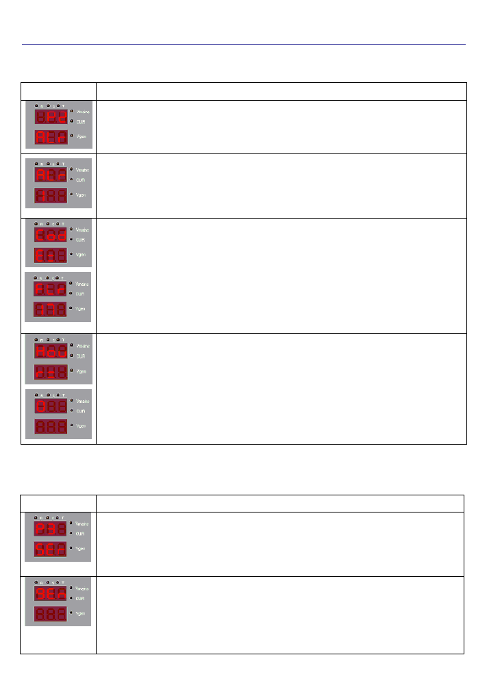
Interface Structure
On the running screen of the unit, the measured values are shown. The operator can navigate through various
measurements bu using the up
or down
buttons.
Screen
Definitions
Descriptions
1
st
Row: V
R-N
Voltage.
2
nd
Row: Blank
While on this screen, pressing the up
button will navigate to the screen shown
below.
While on this screen, pressing the down
button will navigate to the screen shown on
the bottom of this table (Fuel Level).
1
st
Row: V
S-N
Voltage.
2
nd
Row: Blank
Please see Note 1.
15/22
AMF 3.1 USER MANUAL
1
st
Row: V
T-N
Voltage.
2
nd
Row: Blank
Please see Note 1.
1
st
Row: V
R-S
Voltage.
2
nd
Row: Blank
Please see Note 1.
1
st
Row: V
S-T
Voltage.
2
nd
Row: Blank
Please see Note 1.
1
st
Row: V
T-R
Voltage.
2
nd
Row: Blank
Please see Note 1.
1
st
Row: V
U-N
Voltage.
2
nd
Row: Blank
Please see Note 1.
1
st
Row: Abbreviation for Frequency.
2
nd
Row: Mains R Phase Frequency (Hz).
Please see Note 1.
1
st
Row: Abbreviation for Frequency.
2
nd
Row: Generator U Phase Frequency (Hz).
Please see Note 1.
1
st
Row: Abbreviation for Power Factor.
2
nd
Row: Generator U Phase Power Factor.
Please see Note 1.
1
st
Row: Abbreviation for Active Power.
2
nd
Row: Generator U Phase Active Power
(kW)
Please see Note 1.
1
st
Row: Abbreviation for Reactive Power.
2
nd
Row: Generator U Phase Reactive Power
(kVAR).
Please see Note 1.
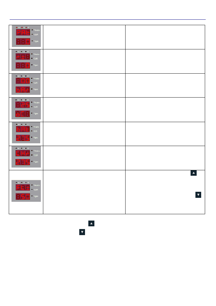
16/22
AMF 3.1 USER MANUAL
1
st
Row: Abbreviation for Apparent Power.
2
nd
Row: Generator U Phase Apparent Power
(kVA).
Please see Note 1.
1
st
Row: Abbreviation for RPM.
2
nd
Row: Generator RPM.
Please see Note 1.
1
st
Row: Oil Pressure Value.
2
nd
Row: Unit of Measurement “bar” or “psi”.
Please see Note 1.
1
st
Row: Coolant Temperature Value.
2
nd
Row: Unit of Measurement “Celcius”.
Please see Note 1.
1
st
Row: Abbreviation for Battery.
2
nd
Row: DC Battery Voltage.
Please see Note 1.
1
st
Row: Abbreviation for Charge.
2
nd
Row: DC Charge Voltage.
Please see Note 1.
1
st
Row: Abbreviation for Fuel Level.
2
nd
Row: Fuel Level (%).
While on this screen, pressing the up
button will navigate to the screen shown on
the top of this table (V
R-N
Voltage).
While on this screen, pressing the down
button will navigate to the screen shown
above.
Note 1:
While on this screen, pressing the up
button will navigate to the screen shown below.
While on this screen, pressing the down
button will navigate to the screen shown above.
MENU SCREEN STRUCTURE
In order to view/edit paramters, the alarm log, the engine running hours and maintenance timers, the
menu must be entered. To enter the AMF 3.1 menu, press and hold the Menu Button for 3 seconds while in
measurement display mode.
17/22
AMF 3.1 USER MANUAL
The AMF 3.1 menu consisit of 3 main categories which are:
P1 PAR: Parameter edit screen
P2 ALR: Alarm log screen
P3 SER: Maintenance timers screen
The desired category can be selected using the Up
and Down
Arrow buttons.
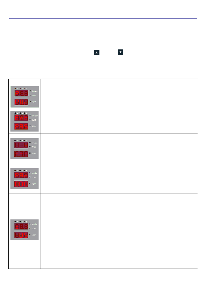
P1: PARAMETER EDIT SCREEN
Screen
Description
The parameter edit screen is the first page that appears after entering the menu. All the parameters are
located inside this menu. From here the parameters can ve viewed and/or edited. In order to access the
parameters press the Menu button to enter the password entry screen located below.
After pressing the Menu button, the screen will display “Ent PAS” for 2 seconds as seen on the left. The
operator will have to enter the correct password which consists of 4 digits. The AMF has 3 user levels which
are 1- User, 2- Service, 3- Factory. The operator can return to the previous screen by pressing the ESC
button.
The password entry will be made starting from the leftmost digit. The active digit will be blinking, indicating that
it is the selected digit. The up and down buttons can be used to change the numerical value of the active digit,
then by pressing the Shift button the active digit can be shifted to the next digit. Once the desired values are
entered, the operator can press the Menu button to confirm it. If the password is wrong, the top display will
indicate “Err” for 2 seconds then return to the measurement screen. If the password entry is correct, the screen
below will appear.
In order to view/edit a parameter, the parameter number must be entered first. The display indicating “000”
shows the parameter number and the leftmost digit will be blinking. Similar to the password entry screen, the
desired parameter number is entered by using the Up and Down buttons, and the next digit is selected by
pressing the Shift button. Once the desired parameter number is entered, the operator can press the Menu
button to confirm it.
The parameter value is displayed as SET= “Parameter Value”. The leftmost digit of the value will be blinking.
The desired value is entered using the Up and Down buttons, and the next digit is selected by pressing the
Shift button. Once the desired value is entered, the parameter can be saved by pressing the Menu button. The
entered can not be outside the limits set by the minimum and maximum value for the respective parameter.
Note :
1
– The “Return to Factory Defaults” operation can not be done while the engine is running. Even
thogh the parameter P30: Return the Factory Defaults is activated, the AMF will not change the
settings.
2
– There is a protection buffer between P36 and P37. The difference between the 2 parameters has to
be more than 3 times the value of P313. (P37
– P36) > P313 x 3
3
– There is a protection buffer between P40 and P41. The difference between the 2 parameters has to
be more than 3 times the value of P314. (P41
– P40) > P314 x 3
4
– There is a protection buffer between P47 and P48. The difference between the 2 parameters has to
be more than 3 times the value of P315. (P48
– P47) > P315 x 3
18/22
AMF 3.1 USER MANUAL
P2-Alarm Log Screen
Screen
Description
The alarm log screen is the 2
nd
page that appears in the menu and can be navigated by pressing the Up and
Down buttons, and pressing the Menu button on the “P2 ALr” screen. The alarm log screen displays the code,
date and stamp for the last 15 alarms in the system. After entering the menu, the screen below appears.
The alarms are listed on this page and the sorting is as last alarm occured - displayed first, and the previous
alarms are listed below that. The operator can scroll through the alarms by using the Up and Down buttons.
The code of the alarm is displayed here.
The screen on the left indicates that the alarm occured is F17 “High Coolant Temperature”. The running hour
time stamp information can be seen by pressing the Down button. The screen similar to the one shown below
will appear.
The total running hours when the at the time the alarm occurred is displayed on this screen. The alarm code
screen displayed above can be reached by pressing the Up button.
P3-Maintenance Timers Screen
Screen
Description
The maintenance timers screen is the 3
rd
page that appears in the menu and can be navigated by pressing
the Up and Down buttons, and pressing the Menu button on the “P3 SEr” screen. There are 4 timer groups
which are: General Maintenance Timer, Engine Maintenance Timer, Total Engine Running Hours, Total
System Running Hours. The desired timer can be navigated using the Up and Down buttons.
The first timer is the General Maintenance Timer and is indicated as “gEn” as seen on the screen on the left.
A few seconds after this indication the second screen seen on the left will appear. The screen indicates that
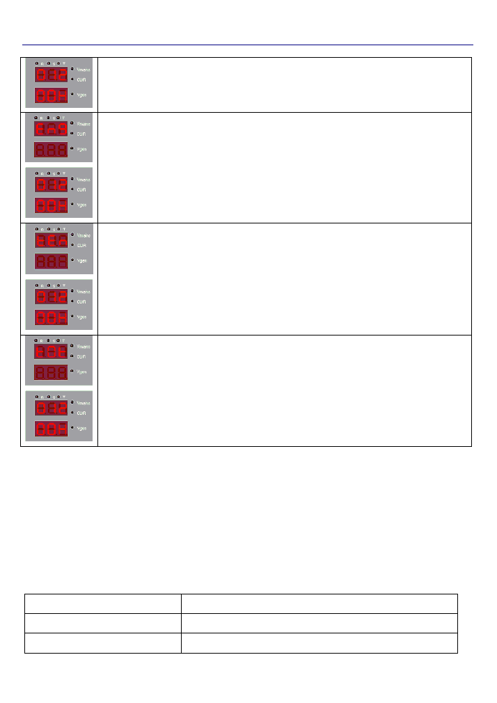
19/22
AMF 3.1 USER MANUAL
there are 1200 hours left until general maintenance.
The second timer is the Engine Maintenance Timer and is indicated as “Eng” as seen on the screen on the
left.
A few seconds after this indication the second screen seen on the left will appear. The screen indicates that
there are 1200 hours left until engine maintenance.
The third timer is the Total Engine Running Hours and is indicated as “tEn” as seen on the screen on the left.
A few seconds after this indication the second screen seen on the left will appear. The screen indicates that
the engine has been running for 1200 hours.
The fourth timer is the Total System Running Hours and is in
dicated as “t0t” as seen on the screen on the left.
A few seconds after this indication the second screen seen on the left will appear. The screen indicates that
the system has been running for a total of 1200 hours.
Digital Input Functions & Descriptions
The inputs indicating “AUX INPUT” on the back panel are the digital inputs of the panel. These inputs are optically
isolated. “COM 7” is the common for auxiliary inputs 1,2,3 and 4. “COM 8” is the common for auxiliary inputs 5 and
6. In typical Generator applications, the COM 7 and COM 8 will be connected to the (+) terminal of the battery, and
the auxiliary inputs will be connected with senders connected to the chasis. The following functions can be
assigned to the auxiliary inputs using their respective parameters P206, P212, P218, P224, P230 and P236.
Note:
The same function should not be assigned to more than 1 input. If there are the same functions assigned to
multiple terminals, that function will not work properly.
The following functions can be assigned to auxiliary inputs.
0: Not Used
If no function will be assigned to the digital input, this function should be
selcted.
1: Oil Pressure Sender
The sender which energizes once the oil pressure drops below a certain
limit is to be assigned this function.
2: Coolant Temperature Sender
The sender which energizes once the coolant temperature exceeds a
certain limit is to be assigned this function.

20/22
AMF 3.1 USER MANUAL
3: Coolant Level Switch
The sender which energizes once the coolant level drops below a certain
limit is to be assigned this function.
4: Aux. Alarm 1
If a signal is received, the alarm is sensed and AUX. 1 led found on the
front panel will be lit.
5: Aux. Alarm 2
If a signal is received, the alarm is sensed and AUX. 2 led found on the
front panel will be lit.
6: Aux. Alarm 3
If a signal is received, the alarm is sensed and AUX. 3 led found on the
front panel will be lit.
7: Aux. Alarm 4
If a signal is received, the alarm is sensed and AUX. 4 led found on the
front panel will be lit.
8: Aux. Alarm 5
If a signal is received, the alarm is sensed and AUX. 5 led found on the
front panel will be lit.
9: Mains Exists
A sort of virtual Mains function. If the Mains is controlled by another
controller, this function can be assigned and the Mains can be simulated
according to the status of the input.
10: Remote Start Disable
If a signal is received the Remote Start function is disabled.
11: Alarm Disable
The alarm checking will be disabled and any alarm occurring on the
generator will be discarded. This function is also known as Fire Pump
Application or War Simulator.
12: Emergency Stop
Emergency stop function.
13: Remote Start
This function is to be used if the Generator will be started and the load
transferred in AUTO Mode while the Mains exists.
14: GCB Feedback
The feedback function for the Generator Circuit Breaker. Can be used as
a safety precaution during contactor operation and maintenance
15: MCB Feedback
The feedback function for the Mains Circuit Breaker. Can be used as a
safety precaution during contactor operation and maintenance
16: GCB Disable
This function de-energizes the Generator Circuit Breaker. The system
will not control this contactor.
17: MCB Disable
This function de-energizes the Mains Circuit Breaker. The system will not
control this contactor.
18: Earthquake
This function is to be assigned if there is an earthquake sensor in the
system. This is a Level 5 alarm independent from the system.
19: Keyboard Disable
This function disables all the buttons on the AMF panel. The buttons will
not be operational.
20: No Mains
Functions the opposit way the Mains Exists function. The panel acts as if
the Mains does not exist regardless of the actual condition of the Mains.
21: Thermic
The thermics from the contactors can be connected to an input with this
function assigned in order to define a Thermic Failure in the system.
22: OFF Button Function
Does the function of pressing the OFF button located on the panel. This
input is only sensed while changing from “0” to “1” and vise versa. The
level is not sensed.
This input is only active while on the measurements screen of the panel.
If an operator is working on the panel and is in any one of the menus
(P1: Parameter Editing, P2: Alarm Log or P3: Maintenance Timers), the
input is temporarily disabled. When returned back to the measurements
screen, the input is re-enabled.
23: AUTO Button Function
Does the function of pressing the AUTO button located on the panel.
This input is only sensed while changing from “0” to “1” and vise versa.
The level is not sensed.
This input is only active while on the measurements screen of the panel.
If an operator is working on the panel and is in any one of the menus
(P1: Parameter Editing, P2: Alarm Log or P3: Maintenance Timers), the
input is temporarily disabled. When returned back to the measurements
screen, the input is re-enabled.
24: TEST Button Function
Does the function of pressing the TEST button located on the panel. This
input is only sensed while changing from “0” to “1” and vise versa. The
level is not sensed.
This input is only active while on the measurements screen of the panel.
If an operator is working on the panel and is in any one of the menus
(P1: Parameter Editing, P2: Alarm Log or P3: Maintenance Timers), the
input is temporarily disabled. When returned back to the measurements

21/22
AMF 3.1 USER MANUAL
screen, the input is re-enabled.
25: Undefined
No function is assigned.
26: Alarm Acknowledge Button Function
AMF31
cihazı üzerindeki Arıza Sil (Korna Sustur) tuşunun
fonksiyonluğunu yerine getirir. Bu giriş 0’dan 1’e geçiş sırasında algılanır.
Seviye algılanmaz.
27: Undefined
No function is assigned.
28: Undefined
No function is assigned.
29: GCB Close Button Function
Does the function of pressing the GCB Close button located on the
panel. This input is only sensed while changing from “0” to “1” and vise
versa. The level is not sensed.
30: GCB Open Button Function
Does the function of pressing the GCB Open button located on the
panel. This input is only sensed while changing from “0” to “1” and vise
versa. The level is not sensed.
31: MCB Close Button Function
Does the function of pressing the MCB Close button located on the
panel. This input is only sensed while
changing from “0” to “1” and vise
versa. The level is not sensed.
32: MCB Open Button Function
Does the function of pressing the GCB Open button located on the
panel. This input is only sensed while changing from “0” to “1” and vise
versa. The level is not sensed.
Digital Output Functions & Descriptions
The outputs indicating “AUX OUT” on the back panel are the digital outputs of the panel. These outputs are all dry
contact relays
. “COM 3” is the common for auxiliary outputs 1,2 and 3. The following functions can be assigned to
the auxiliary outputs using their respective parameters P254, P256 and P258.
0: Not Used
If no function will be assigned to the digital output, this function should be
selcted.
1: Engine Running
If the engine has started and alarm delay time has passed this output will
be activated.
2: AUTO Ready
If the panel is in AUTO mode, this output will be activated.
3: Mode Selection
If the Menu has been entered from the front panel, this output will be
activated.
4: B,C (Class 1 & 2) Class Alarm (Horn)
Output
In the Parameter List, the alarm classes are defined as follows;
Class A : 0
Class B : 1
Class C : 2
Class D : 3
Class E : 4
Class F : 5
Class A alarms are numerically defined as “0”.
In the case of a Class 1 or 2 alarm, this output is activated.
If the parameter P20 “Alarm Maximum Output Time” is defined as “0”,
this output will constantly be active. If parameter P20 is set at a value
which is >0, then this output will be activated for that time period then be
deactivated.
5: D,E,F (Class 3, 4 & 5) Class Alarm
(Horn) Output
In the case of a Class 3, 4 or 5 alarm, this output is activated.
If the parameter P20 “Alarm Maximum Output Time” is defined as “0”,
this output will constantly be active. If parameter P20 is set at a value
which is >0, then this output will be activated for that time period then be
deactivated.
6: B,C,D,E,F Class Alarm (Horn) Output
In the case of a Class 1, 2, 3, 4 or 5 alarm, this output is activated.
If the parameter P20 “Alarm Maximum Output Time” is defined as “0”,
this output will constantly be active. If parameter P20 is set at a value
which is >0, then this output will be activated for that time period then be
deactivated.
7: Preheat Output
If there is a requirement of pre-heating before engine cranking this
function output is used. The preheat time can be set using paramter P19.
8: Generator Loaded Output
If the system is fed through the generator contactor, this output will be

22/22
AMF 3.1 USER MANUAL
activated.
9: Mains Loaded Output
If the system is fed through the mains contactor, this output will be
activated.
10: Fuel Pump Output
If there is a requirement of automatic fueling this output will be activated.
If the fuel level drops below the limit set by parameter P300 this output is
activated and is deactivated when the fuel level reaches the upper limit
set by parameter P301.
11: Undefined
No function is assigned.
12: Louvre Control Output
This output is activated when the fuel solenoid is energized and
deactivated when the engine stos.
13: Fuel Solenoid Output
The same functions as the Fuel Solenoid output can be assigned using
this function.
14: Telecom Running
This output is activated once the battery voltage drops below the limit set
by P26 and is deactivated once the voltage reaches the limit set by P27.
There is a 5 second delay between levels.
15: Generator Voltage or Speed Alarm
If there is an alarm regarding the generator voltages or frequency, this
output is activated.
16: Analog Low Oil Pressure Alarm
If there is an alarm caused by the analog oil pressure sender, this alarm
is activated.
17: Digital Oil Pressure Alarm
If there is an alarm caused by the digital oil pressure switch, this alarm is
activated.
18: Speed Alarm
If there is and alarm caused by the frequency, this alarm is activated.
19: Undefined
No function is assigned.
20: Start Failure
If the generator failed to start, this output is activated.
Document Version
Versiyon No : 01
Değişiklik Tarihi : 05.05.2014
Değişikliği Yapan : Hasip TUNA
Değişiklik Nedeni : Yayım