Full Text Searchable PDF User Manual
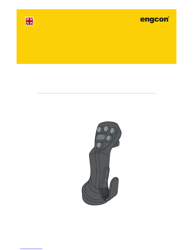
engcon DC2
INSTALLATION INSTRUCTIONS
Translation of the original Swedish
instructions
Part no.
|
841616
Version
|
201702
| ENGCON MIG2 |
2
Instruction Manual
General
These instructions are designed to describe replacement of the original base machine
joystick with the joystick supplied with the engcon DC2. It is important that the joysticks
are used together with engcon DC2 for the Declaration of Incorporation in the installation
instructions to be valid.
In addition to these installation instructions, you must study and understand the safety
information applicable to the base machine concerned, as well as any other equipment
involved.
Do not attempt to install, use or maintain your tiltrotator/rotator and its supplied equip-
ment before reading and understanding all information about the tiltrotator/rotator,
its supplementary equipment and the base machine. Pay particular attention to the
safety information.
WARNING!
Other safety instructions are found in the engcon DC2 instruction manual.
WARNING!

3
engcon DC2
Table of Contents
1
Safety directives ��������������������������������������������������������������������������������������4
1.1 General ................................................................................................................ 4
1.2
Safety checklist .................................................................................................... 4
1.3
The environment .................................................................................................. 5
2
Symbols in the installation instructions ������������������������������������������������5
3
Checking delivered parts ������������������������������������������������������������������������6
3.1
841519 MIG2 2 rollers ......................................................................................... 6
3.2
841520 MIG2 3 rollers ......................................................................................... 6
3.3
841521 MIG2 3 rollers, FNR ................................................................................ 6
3.4
841522 MIG2 4 rollers ......................................................................................... 7
3.5
841523 MIG2 4 rollers, FNR ................................................................................ 7
3.6
841524 MIG2 5 rollers ......................................................................................... 7
3.7
841525 MIG2 5 rollers, FNR ................................................................................ 8
3.8
841528 MIG2 6 rollers ......................................................................................... 8
3.9
841529 MIG2 6 rollers, FNR ................................................................................ 8
4
Joystick installation ���������������������������������������������������������������������������������9
4.1
Area A .................................................................................................................. 9
4.1.1 Removal of original joystick ...........................................................................
9
4.1.2 Installation, screw ..........................................................................................
9
4.1.3 Cable routing ...............................................................................................
10
4.1.4
Attachment ..................................................................................................
10
4.1.5 Reinstallation ................................................................................................
11
4.1.6 Hand support ...............................................................................................
12
4.1.7 Attachment Kit .............................................................................................
12
4.1.8 Standard Bellow Adapter.............................................................................
13
4.1.9 Bellow Adapter Kit .......................................................................................
13
4.2
Area B ................................................................................................................ 14
4.2.1 MIG2 Left (842020) .....................................................................................
14
4.2.2 MIG2 Right (852047) ...................................................................................
15
4.2.3 MIG2 Right FNR (852046) ..........................................................................
16
4.3
Area C ................................................................................................................ 17
5
Documenting the installation ����������������������������������������������������������������18
5.1
Build your own decal .......................................................................................... 18
5.2
Affix the decals in a spot easily visible to the driver ........................................... 19
5.3
Cut away misleading information on the original decals .................................... 19
5.4
Update the engcon instructions for use ............................................................. 20
5.5
Update the machine's original instructions for use ............................................. 20
5.6
Decals for multiple user banks ........................................................................... 21
4
Instruction Manual
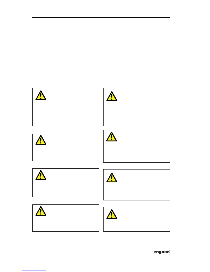
1 Safety directives
1�2 Safety checklist
1�1 General
It is of the utmost importance that you
study and understand all the warning texts
before beginning to install/use the engcon
DC2. The warning texts highlight potential
risks and how to avoid them.
If in the slightest doubt, contact your em-
ployer or supplier.
Remember: a great many unnecessary
risks can be mitigated through sound judge-
ment and knowledge of the machinery. The
intended operator should therefore set
aside time to learn how to safely handle the
engcon DC2 before the machine is used.
Crushing risk from moving parts. Risk
of personal injury.
WARNING!
If you have the slightest doubt concern-
ing your knowledge or work regarding
safety details, contact your dealer or
engcon Sweden.
WARNING!
Check that the function decal matches
the machine functions before com-
mencing work. Risk of personal injury.
WARNING!
Defective or damaged equipment can
cause personal injury, damage to the
environment and/or property damage.
Ensure that service and maintenance
are carried out as recommended.
WARNING!
Never attempt to increase the maximum
capacity of the equipment by modifica-
tions not approved by the supplier.
WARNING!
Replace damaged and/or illegible de-
cals and warning signs before the ma-
chine is used. Risk of personal injury.
WARNING!
Maintenance and repair of the electri-
cal system may only be carried out by
professionally qualified persons.
WARNING!
Assembly and installation may only be
carried out at a workshop authorised by
the supplier. Changes to the assembly
may not be carried out without the man-
ufacturer’s consent.
WARNING!
5
engcon DC2
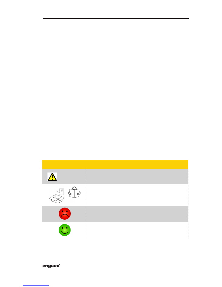
2 Symbols in the installation instructions
1�3 The environment
Symbol
Description
WARNING
Risk of personal injury and/or property damage
Read the accompanying documentation for more information.
No/Incorrect measure
Yes/Correct measure
engcon's tiltrotators comprise at least 99 per cent recyclable material. engcon makes
constant efforts to reduce its environmental impact. All assembly and/or service work
must take place in compliance with applicable legislation and ordinances within the en-
vironmental, health and occupational safety areas. This includes all work, handling, stor-
age and processing of residual materials.
Spillage must be avoided and taken care of when it occurs to prevent pollution of soil and
water.
Note that hazardous waste may only be handled by people so authorised. All waste pro-
duced must be taken care of in compliance with applicable legislation and ordinances:
•
Metallic materials must be recycled.
•
Hydraulic hoses are normally used for energy recovery (sort as hazardous waste).
•
Oils and greases are normally used for energy recovery (sort as hazardous
waste).
•
Electronic components must be recycled for materials (sort as hazardous waste).
•
Packaging to be source sorted and recycled for materials.
•
Paper to be source sorted and recycled for materials.
If in doubt, contact the environmental manager at engcon.
6
Instruction Manual
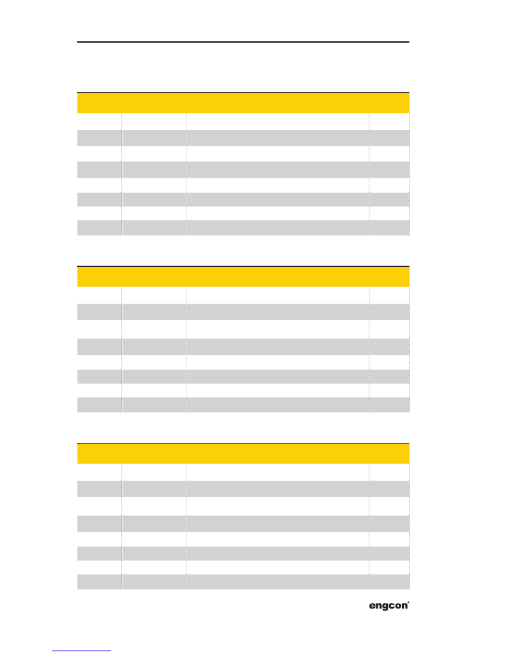
3 Checking delivered parts
3�1 841519 MIG2 2 rollers
3�2 841520 MIG2 3 rollers
3�3 841521 MIG2 3 rollers, FNR
Position
Part
Designation
Quantity
1
841288
Joystick MIG2, left, one roller
1
2
841289
Joystick MIG2, right, one roller
1
3
841190
Joystick cabling
1
4
841868
Decal, MIG2
1
5
841869
Decal, MIG2
1
6
841161
Decal, machine functions symbol library – transparent
2
7
841858
Installation kit
1
8
841184
Warning decals for original instructions for use
1
Position
Part
Designation
Quantity
1
841291
Joystick MIG2, left, two rollers
1
2
841289
Joystick MIG2, right, one roller
1
3
841190
Joystick cabling
1
4
841868
Decal, MIG2
1
5
841869
Decal, MIG2
1
6
841161
Decal, machine functions symbol library – transparent
2
7
841858
Installation kit
1
8
842047
Warning decals for original instructions for use
1
Position
Part
Designation
Quantity
1
841291
Joystick MIG2, left, two rollers
1
2
841290
Joystick MIG2, right, one roller, FNR
1
3
841190
Joystick cabling
1
4
841868
Decal, MIG2
1
5
841869
Decal, MIG2
1
6
841161
Decal, machine functions symbol library – transparent
2
7
841858
Installation kit
1
8
842047
Warning decals for original instructions for use
1
7
engcon DC2
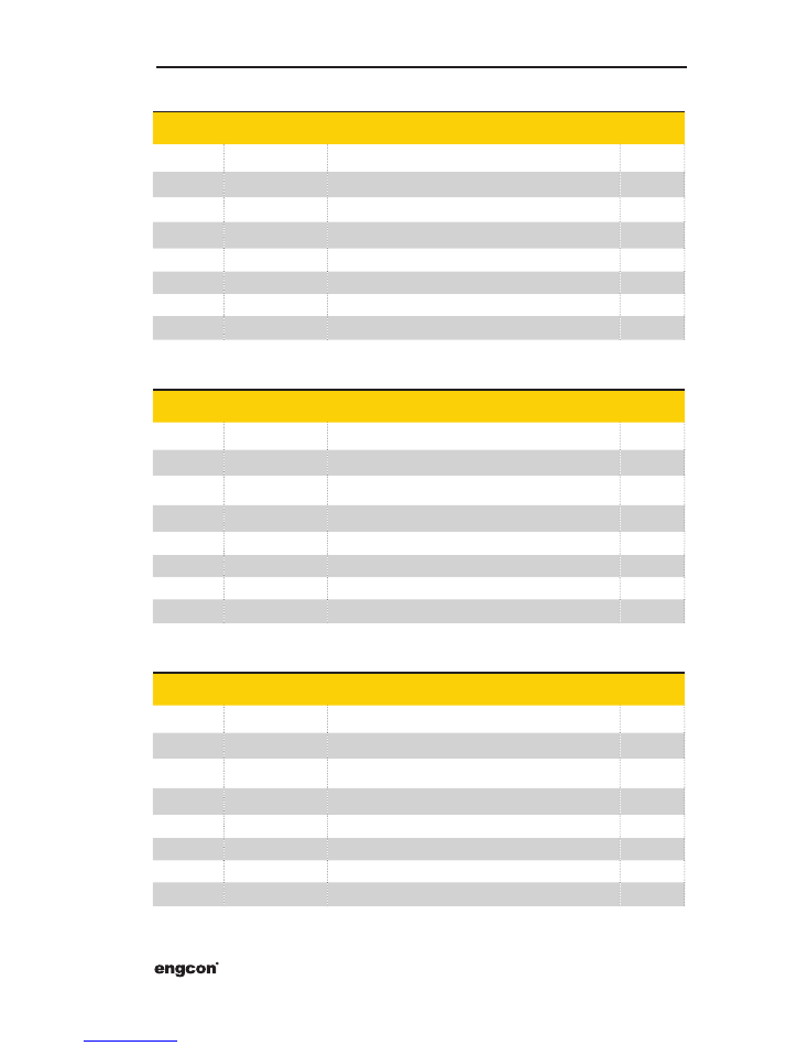
3�4 841522 MIG2 4 rollers
3�5 841523 MIG2 4 rollers, FNR
3�6 841524 MIG2 5 rollers
Position
Part
Designation
Quantity
1
841291
Joystick MIG2, left, two rollers
1
2
841292
Joystick MIG2, right, two rollers
1
3
841190
Joystick cabling
1
4
841868
Decal, MIG2
1
5
841869
Decal, MIG2
1
6
841161
Decal, machine functions symbol library – transparent
2
7
841858
Installation kit
1
8
842047
Warning decals for original instructions for use
1
Position
Part
Designation
Quantity
1
841291
Joystick MIG2, left, two rollers
1
2
841293
Joystick MIG2, right, two rollers, FNR
1
3
841190
Joystick cabling
1
4
841868
Decal, MIG2
1
5
841869
Decal, MIG2
1
6
841161
Decal, machine functions symbol library – transparent
2
7
841858
Installation kit
1
8
842047
Warning decals for original instructions for use
1
Position
Part
Designation
Quantity
1
841294
Joystick MIG2, left, three rollers
1
2
841292
Joystick MIG2, right, two rollers
1
3
841190
Joystick cabling
1
4
841868
Decal, MIG2
1
5
841869
Decal, MIG2
1
6
841161
Decal, machine functions symbol library – transparent
2
7
841858
Installation kit
1
8
842047
Warning decals for original instructions for use
1
8
Instruction Manual
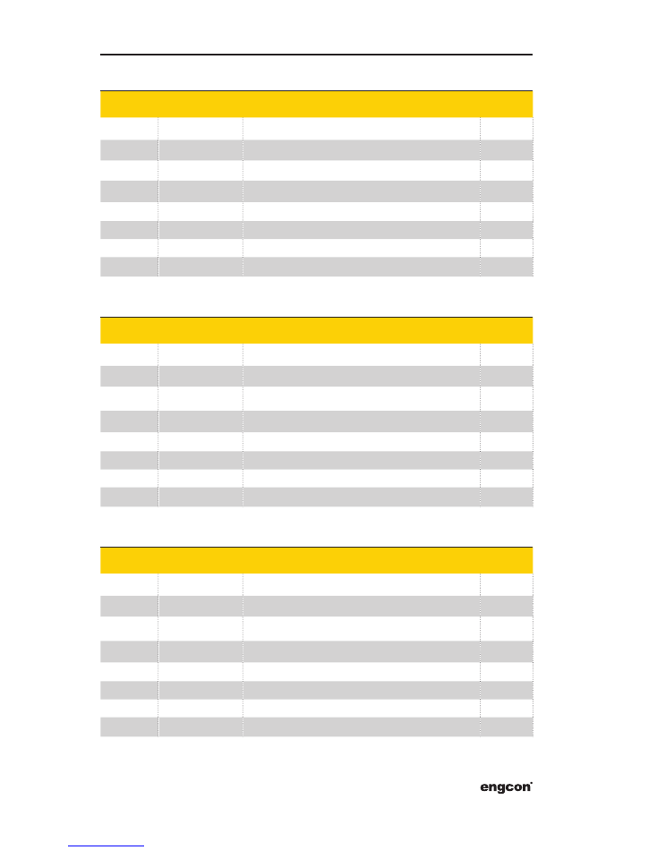
3�7 841525 MIG2 5 rollers, FNR
3�8 841528 MIG2 6 rollers
3�9 841529 MIG2 6 rollers, FNR
Position
Part
Designation
Quantity
1
841294
Joystick MIG2, left, three rollers
1
2
841293
Joystick MIG2, right, two rollers, FNR
1
3
841190
Joystick cabling
1
4
841868
Decal, MIG2
1
5
841869
Decal, MIG2
1
6
841161
Decal, machine functions symbol library – transparent
2
7
841858
Installation kit
1
8
842047
Warning decals for original instructions for use
1
Position
Part
Designation
Quantity
1
841294
Joystick MIG2, left, three rollers
1
2
841295
Joystick MIG2, right, three rollers
1
3
841190
Joystick cabling
1
4
841868
Decal, MIG2
1
5
841869
Decal, MIG2
1
6
841161
Decal, machine functions symbol library – transparent
2
7
841858
Installation kit
1
8
842047
Warning decals for original instructions for use
1
Position
Part
Designation
Quantity
1
841294
Joystick MIG2, left, three rollers
1.
2
842008
Joystick MIG2, right, three rollers, FNR
1
3
841190
Joystick cabling
1
4
841868
Decal, MIG2
1
5
841869
Decal, MIG2
1
6
841161
Decal, machine functions symbol library – transparent
2
7
841858
Installation kit
1
8
842047
Warning decals for original instructions for use
1
9
engcon DC2
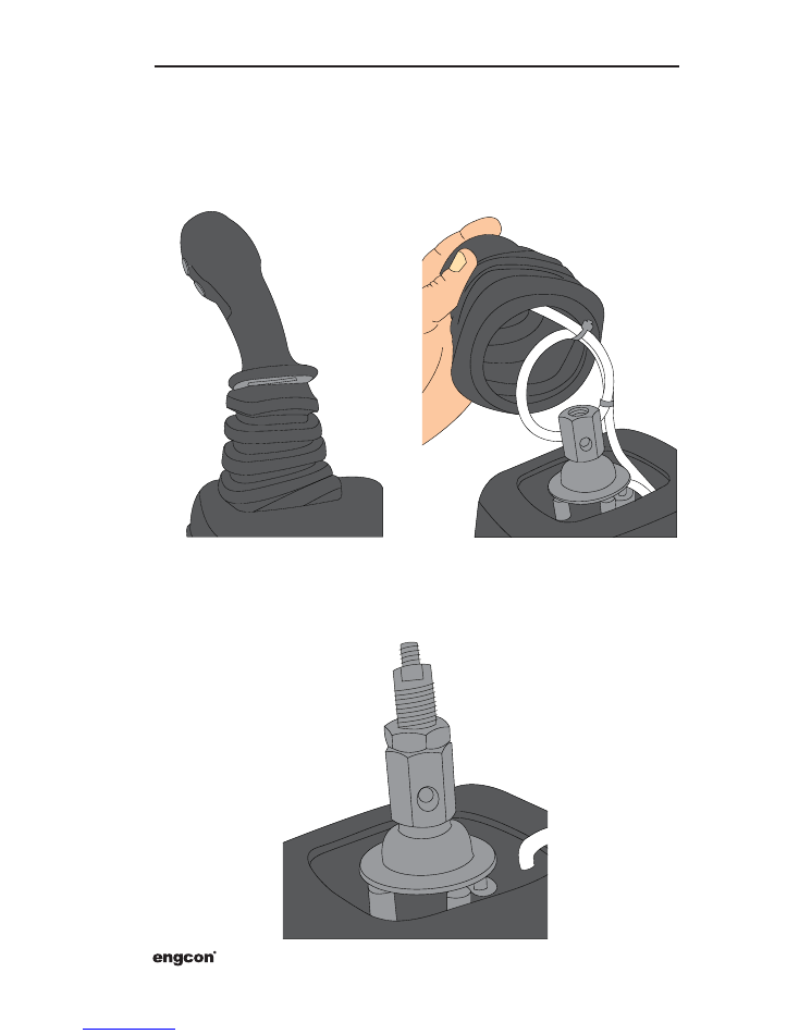
4 Joystick installation
4�1 Area A
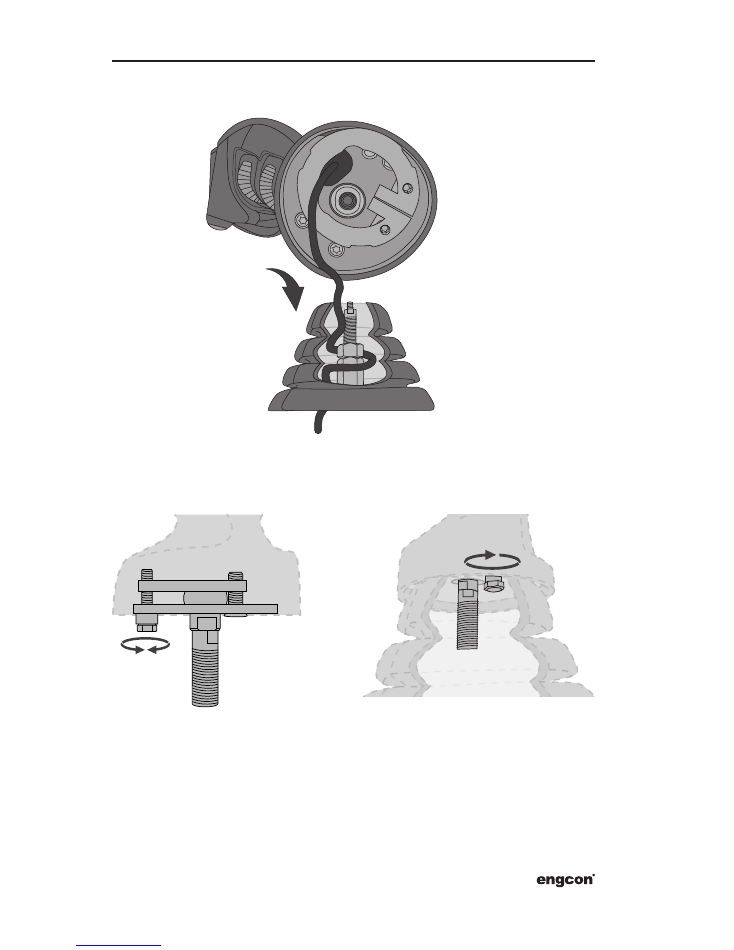
4.1.1 Removal of original joystick
4.1.2 Installation, screw
You may need to shorten the screw to the appropriate length before you mount it as
shown in the picture below.
10
Instruction Manual
4.1.3 Cable routing
4.1.4
Attachment
11
engcon DC2
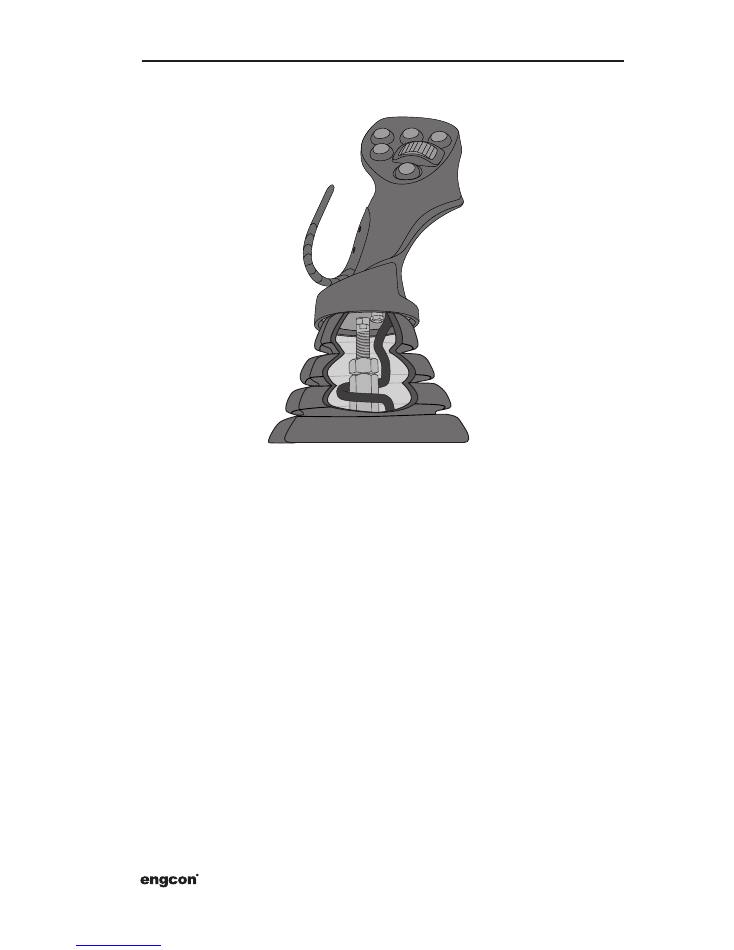
4.1.5 Reinstallation
12
Instruction Manual
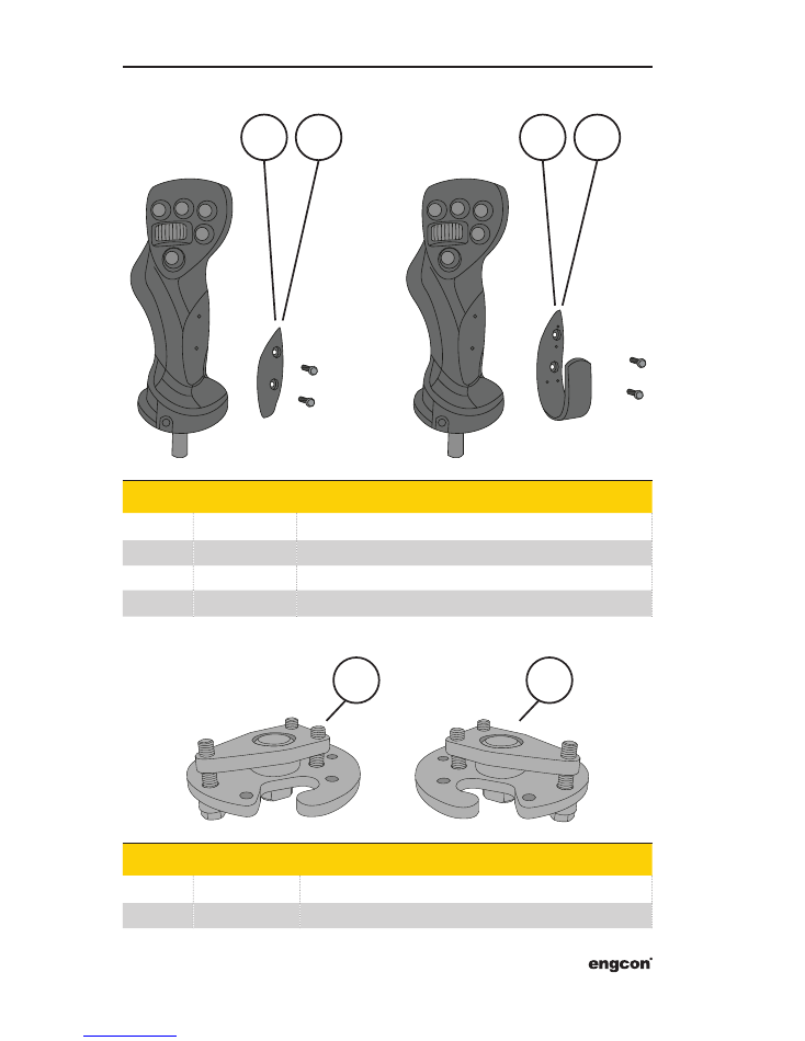
4.1.6 Hand support
4.1.7 Attachment Kit
Position
Part
Designation
1
841892
Cover Disc Hand Support Left
2
841893
Cover Disc Hand Support Right
3
841865
Hand Support Left
4
841866
Hand Support Right
1
1
2
3
4
Position
Part
Designation
1
8000196
Attachment Kit MIG2 Left
2
8000195
Attachment Kit MIG2 Right
2
13
engcon DC2
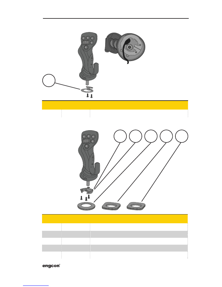
4.1.9 Bellow Adapter Kit
4.1.8 Standard Bellow Adapter
Position
Part
Designation
1
1033831
Bellow Adapter
Position
Part
Designation
1
1039301
Bellow Adapter Left
2
1039300
Bellow Adapter Right
3
8000191
Bellow Adapter Kit - CAT 308E - MIG2
4
8000190
Bellow Adapter Kit - Liebherr - MIG2
5
8000291
Bellow Adapter Kit Hyundai
1
1
2
3
4
5
14
Instruction Manual
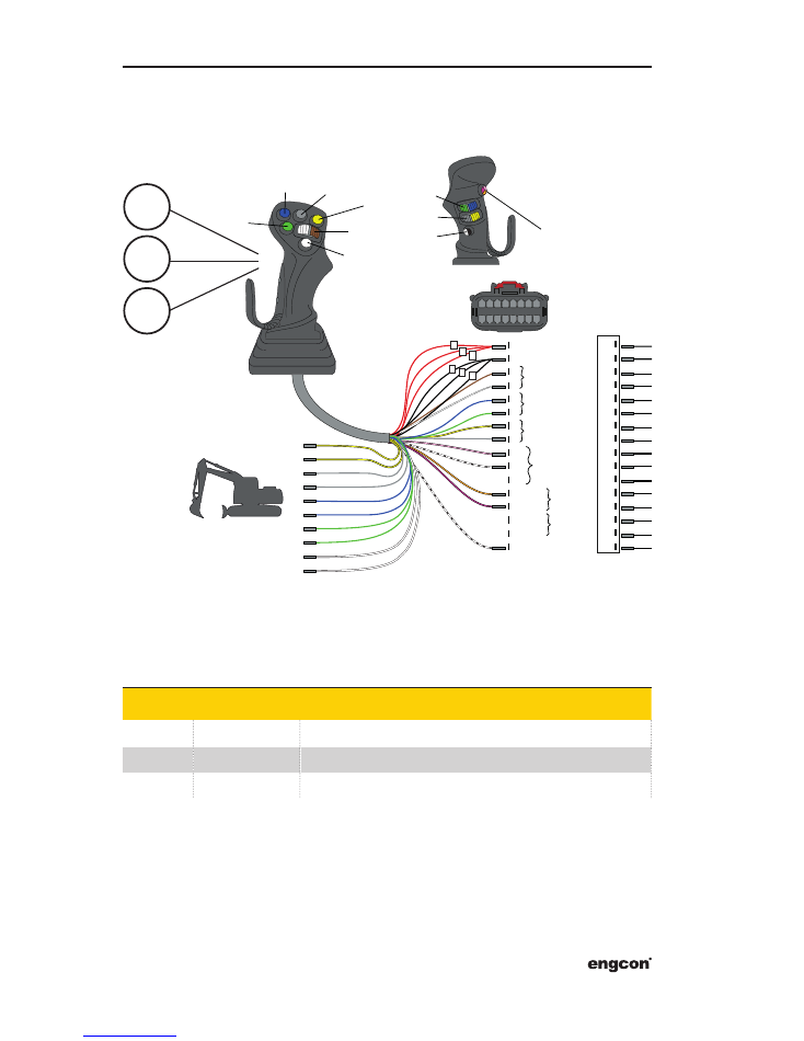
4�2 Area B
4.2.1 MIG2 Left (842020)
Position
Part
Designation
1
841288
Joystick MIG2, left, one roller
2
841291
Joystick MIG2, left, two rollers
3
841294
Joystick MIG2, left, three rollers
A1 - OUT1
GND
+5V
RD
BK
BN
WH
BU
GN
YE
GY
PK
BK/WH
OR
VT
BK/WH
A2 - OUT2
A3
NO
NC
NO
NC
+12/24V
NO
LD1-SW6
1
2
3
4
5
6
7
8
9
10
11
12
13
14
15
16
RD3-SW7
1
1
2
2
3
3
YE
YE
GY
GY
BU
BU
GN
GN
WH
WH
8
1
9
16
852020
WH
BN
GN
YE
GY
PK
BU
RD
BK
VT
WH/BN
WH/GN
WH/YE
WH/GY
WH/PK
WH/BU
1
2
3
4
5
6
7
8
9
10
11
12
13
14
15
16
SW4
SW5
SW1
SW2
SW3
OUT1
OUT3
OUT2
SW7
SW6
1
2
3
15
engcon DC2
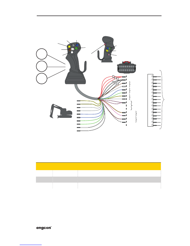
4.2.2 MIG2 Right (852047)
Position
Part
Designation
1
841289
Joystick MIG2, right, one roller
2
841292
Joystick MIG2, right, two rollers
3
841295
Joystick MIG2, right, three rollers
A1 - OUT1
GND
+5V
RD
BK
BN
WH
YE
GY
PK
OR
VT
BK/WH
GY/RD
A2 - OUT2
A3
NO
NC
NO
NC
+12/24V
NO
RD1-SW6
1
2
3
4
5
6
7
8
9
10
11
12
13
14
15
16
RD2-SW7
1
1
2
2
3
3
YE
YE
GY
GY
BU
BU
GN
GN
WH
WH
8
1
9
16
852047
SW4
SW5
SW1
SW2
SW3
OUT1
OUT3
OUT2
SW7
SW6
BU
GN
WH
BN
GN
YE
GY
PK
BU
RD
BK
BK
BK
VT
GY/PK
RD/BU
WH/GN
WH/YE
1
2
3
4
5
6
7
8
9
10
11
12
13
14
15
16
841
190
841190
1
2
3
16
Instruction Manual
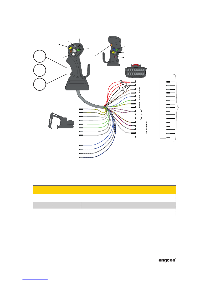
4.2.3 MIG2 Right FNR (852046)
Position
Part
Designation
1
841290
Joystick MIG2, right, one roller, FNR
2
841293
Joystick MIG2, right, two rollers, FNR
3
842008
Joystick MIG2, right, three rollers, FNR
841190
1
2
3
A1 - OUT1
GND
+5V
RD
BK
BN
WH
YE
GY
PK
OR
VT
BK/WH
GY/RD
A2 - OUT2
A3
NO
NC
NO
NC
+12/24V
NO
RD1 - SW6
1
2
3
4
5
6
7
8
9
10
11
12
13
14
15
16
RD2 - SW7
1
1
2
2
3
3
YE
YE
GY
GY
GN
GN
WH
WH
BU
BU/WH
BK/GY
BK/BU
8
1
9
16
852046
WH
BN
GN
YE
GY
PK
BU
RD
BK
BK
BK
VT
GY/PK
RD/BU
WH/GN
WH/YE
1
2
3
4
5
6
7
8
9
10
11
12
13
14
15
16
OUT3
OUT2
SW7
SW6
+
F
N
R
SW4
SW5
SW1
SW2
OUT1
SW3
BU
GN
841
190
17
engcon DC2
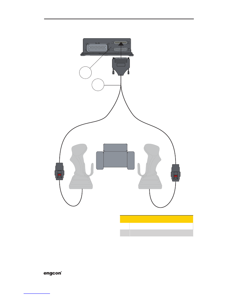
4�3 Area C
Pos Part
1
841105
2
841190
R
L
1
2
18
Instruction Manual
1
2
USER 1
SHEAR
1
2
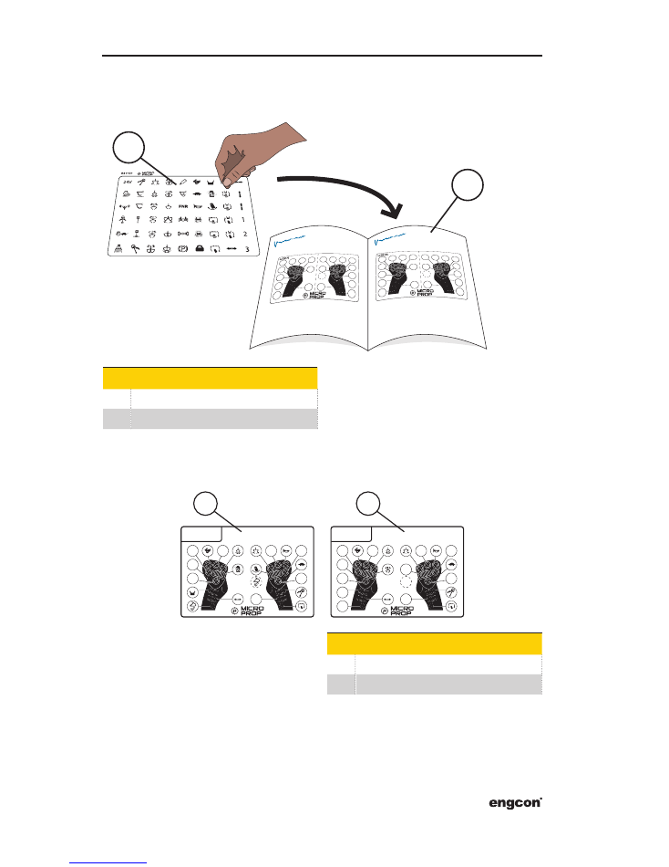
5 Documenting the installation
5�1 Build your own decal
Pos Designation
1
841161
2
841868 or 848869
Examples:
Pos Designation
1
USER 1 decal
2
SHEAR decal (tilt hydraulics)
19
engcon DC2
USER 1
USER 2
SHEAR
1
2
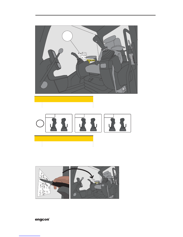
5.2 Affix the decals in a spot easily visible to the driver
Pos Designation
1
Joystick decals
Pos Designation
2
Example, decal location
5�3 Cut away misleading information on the original decals
Note that machine functions that still apply must not be cut away.
Note that engcon decals do not fully replace the machine's original decals.
20
Instruction Manual
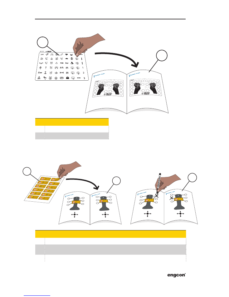
5�4 Update the engcon instructions for use
Pos Designation
1
841161
2
Instructions for use, engcon
5�5 Update the machine's original instructions for use
Pos Designation
1
842047
2
Locate the decal such that it makes clear the joystick has been replaced and that there is information
on new functions in the engcon instructions for use.
3
Where necessary, emphasise changes by crossing out misleading or ambiguous information.
3
2
1
1
2
21
engcon DC2
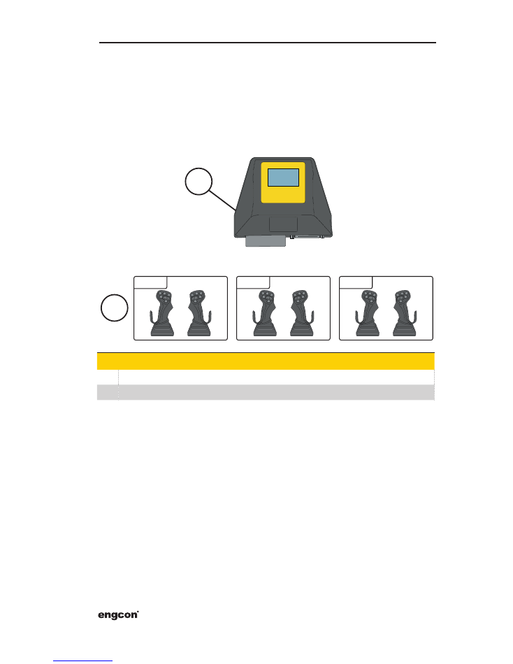
5�6 Decals for multiple user banks
If more than one user bank is activated, the installer must affix one decal per user bank.
The cab module must then also be fitted so that the driver can see the display and there-
by see which user bank is active.
The installer is then responsible for ensuring that there is one decal per user bank and
that the base machine's instruction manual is updated with this information.
Pos Designation
1
The current user is shown in the display
2
Each user must have a corresponding decal
1
2
USER 1
USER 1
USER 2
SHEAR

Notes

Notes

www.engcon.com
TOOL SYSTEMS FOR INCREASED PROFITABILITY
engcon Sweden AB Transportgatan 5, SE-833 36 Strömsund
|
Tel +46 670 650 400
|
Fax +46 670 650 457
|
Email sweden@engcon.com