Full Text Searchable PDF User Manual
1
ECA Electronic Engineering Pty LTD
GSM Access Control Model GSM18v3 / User Manual V3
GSM Access Control model GSM18v4
User manual Version June 2016
1. General Overview
The GSM18v4 Access Control is our basic GSM access control system for cellular gate\door access
control. The unit can store a list of authorized users and when someone calls the SIM of the unit, the
unit hangs-up the call and checks if the phone number of the caller is in the list of the unit, and only if
he is an authorized user, a pulse generated by internal relay to trigger the gate\door to open. There is
no cost of call to the user. The unit can hold up to 1600 authorized users and up to 400 restricted
(limited) users, totally 2000 users.
2. General Product Description
Weight:
120 grams.
Input voltage:
12V DC
Air humidity range:
5% - 85%
RoHS compliance:
Fully compliant with the EU RoHS and WEEE Directives
Casing material:
The case made from plastic PC IP54.
GSM frequencies:
The unit supports quad band GSM frequencies
3. Installation
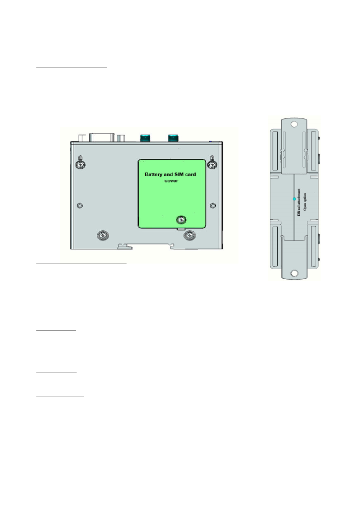
SIM card insertion
With a Philips screw driver open the SIM card drawer cover and insert the SIM card.
Make sure the SIM card is capable to receive incoming SMS messages and to identify a caller ID.
GSM antenna
The GSM antenna needs to be connected to the SMA connector in the front panel of the unit.
Power Supply
The power supply for the unit must be a single voltage source of regulated power supply between 10V-
14V Dc capable of providing a Min 2Amp peak during an active transmission. The unit is protected
from supply voltage reversal. An internal fuse ensures an electrical safety according to EN60950
standard. This fuse is not removable.

2
ECA Electronic Engineering Pty LTD
GSM Access Control Model GSM18v3 / User Manual V3
Connections
• Red wire: Positive + 12V
• Black wire: Negative -V
• Yellow wire: Not in use
• White wire: Common (contact of the internal relay)
• Green wire: N.O. (Normally Open contact of the internal relay)
• Yellow wire: Not in use
Appling power to the unit
Before applying power,
TEST THE SIM CARD IN YOUR PHONE
and make sure you can make a
call and it is activated and has its ID number on. Unscrew the cover on the unit and insert the SIM.
NOTE
! Please wait 3 minutes to allow the unit to load the software after powering up the unit on. The
LED in the unit will turn on to indicate the unit is ready for use.
System operation
A registered user can gain access by calling the unit which will automatically activate its output to
trigger the gate/door to open. If the user’s mobile number is a privet number, then he can gain access
by sending an SMS to the unit. If access by SMS is desired, then SMS: O (lowercase or uppercase) to
the unit.
4. Programming the unit
Make sure the Green LED is ON and the SIM card has a credit to make calls.
The unit can be programmed by SMS commands.
Whenever you program the unit by SMS, you must start the SMS message with the letter
P
(Password)
followed by the
Manufacture’s Default Password which is 1234
and then the desired command.
For each SMS command you send, you will receive an SMS reply from the unit to confirm.
Note! If there is no credit on the SIM card, the unit will not send an SMS confirmation back.
Programming phone numbers of normal users (0 - 1600)
Example for how to register and add three phone numbers by SMS command;
P.1234A.0417315263.0418655002.0411136585
“P” means: password
1234: Manufacture’s default password.
“A” meaning: Add the following number(s).
“.” The dot means end of a number.
0417315263 : phone number added.
0418655002 : phone number added.
0411136585 : phone number added.
You must write and send the SMS exactly as written above, with points between
each phone number
.
If you failed to register several numbers on one go, try to
send them one by one as follow:
P.1234A.0417315263

3
ECA Electronic Engineering Pty LTD
GSM Access Control Model GSM18v3 / User Manual V3
Deleting registered phone numbers by SMS command
To
Delete All
numbers
P.1234format
In order to delete registered phone numbers send SMS with the following structure:
P.1234D.0417315263.0418655002
“P” means: password
1234: Manufacture’s default password.
“D” meaning: DELETE the following number(s).
“.” The dot means end of a number.
0417315263 : phone number added.
Setting the internal clock by SMS command
The unit’s internal clock is automatically updated with the local time however in some old mobile networks this
might not be applicable and therefore the unit’s internal clock should be updated by a SMS as follows;
P.1234CU
Setting up special users (phone numbers)
(0 - 400)
by SMS command
Note: A special phone Number is a user who has limited number of eateries to access the property, or
limited to
certain times
or special
days of the week
.
Make sure to update the internal clock before you register special phone number as shown above.
In order to register special phone numbers and set time zone for each number by SMS do as follows;
*
To allow
unlimited number of entries
with
limited time zone and limited days of the week for a
special number:
P.1234AS.0418317452.1.
0900.1700.
127
“
AS
” meaning:
A
dd
S
pecial number
“ 1” meaning : To allow unlimited numbers of entries.
“
900.1700”
meaning: To limit entries between 9:00AM to 17:00PM.
“
127
”
meaning: limiting entries for days of the week; Sundays Mondays & Saturdays.
*
To allow
limited number of entries with unlimited times or days for a special number:
P.1234AS.041736690.3.
6
“
AS
” meaning:
A
dd
S
pecial number
“ 3” meaning : Allow limited entries for this especial number.
“6”
meaning : To limit 6 entries only.
Pls insert “
0,0”
instead of the time if you do not want to limit the entries between any time
.
Delete Special phone numbers by SMS
In order to delete special phone numbers send the following
P.1234DS.0416824036,0433256815
“
DS
” meaning :
D
elete
S
pecial number (or numbers)

4
ECA Electronic Engineering Pty LTD
GSM Access Control Model GSM18v3 / User Manual V3
Changing the default programming password code by SMS
In order to change the “password programming code” you need to send an SMS with the following structure:
P.1234NP.1111
P.1234 (the default code) required for any SMS command
The letters NP stands for “New Password” then the numbers 1111 are the new password
which should be used from now on in any program SMS you send to the unit. "P.1111"
Gate Opening trigger Delay
The default pulse trigger of the internal; relay is 3 seconds. In order to change the trigger opening time
of the relay to 1 seconds (for example), send SMS with the following structure
P.1234GOD.1,1,1,1
The Maximum time of the relay to stay open is 60 second
Info
In order to receive information on the numbers and special numbers stored in unit’s memory send the
following SMS command:
P.1234INFO
Disable/Enable the unit
The unit default status is enabled. In order to disable the unit send the following SMS
P.1234EN.0
I
n order to enable the unit to function send
P.1234EN.1
Open All
The "Open All" feature will allow the gate to open for any one that calls the unit.
To enable this feature send SMS
P.1234open.1
To disable this feature send
P.1234open.0
REST
In order to reset the unit send the following
P.1234RESET
ECA
Electronic Engineering Pty. LTD.
Factory Address: No. 76 - 80 Levanswell Rd Moorabbi n Vic. 3189
ecaelcetronic@bigpond.com
www.gatesonsolar.com
Tel: +61 3 95720535