Full Text Searchable PDF User Manual
www.distech-controls.com
1/10
1. Product Description
The Allure
™
EC-Smart-Vue series sensors are designed to interface
with any ECB or ECL-Series controller to provide precision local
temperature sensing, information display of system status, and a
variety of control functions that can be accessed by room occupants.
Through its user-friendly interface, occupants can view and adjust
environmental settings to their liking, for example, view the space
temperature, adjust the setpoint, and apply occupancy overrides with
the Allure EC-Smart-Vue room temperature sensor. In addition to this,
the Allure EC-Smart-Vue-H sensor can measure the room’s humidity
level, the Allure EC-Smart-Vue-M sensor has a motion activated
occupancy sensor, the Allure EC-Smart-Vue-C sensor has a CO
2
sensor to measure air-quality, the Allure EC-Smart-Vue-CM sensor
has both an occupancy and CO
2
sensor, the Allure EC-Smart-Vue-CH
sensor has both a humidity and CO
2
sensor, the Allure
EC-Smart-Vue-HM sensor has a humidity sensor with a built-in motion
detector, and the Allure EC-Smart-Vue-CHM sensor has a humidity
and CO
2
sensor with a built-in motion detector.
With the EC-
gfx
Program programming tool, you can create your own
tailor-made display control features that make full use of all Allure
EC-Smart-Vue’s capabilities. For example, you can program the
display to give users feedback on their setpoint selection with the
ECO-Vue
™
icon that shows more leaves for a setting that not only
cares for the environment, but one that also reduces operating costs. A
five-character alphanumeric display is available for showing messages.
A password protected technician mode allows an installer to perform
commissioning and troubleshooting. When connected with the
ECB-VAV or ECL-VAV series, commissioning can start immediately
after installation, as the Allure EC-Smart-Vue sensor can be used as a
hand-held tool to select the appropriate controller application for the
type of HVAC equipment to be controlled, to perform air balancing of
the system without requiring an onsite controls engineer, and to
troubleshoot the system.
Mounting hardware with a separate sub-base is provided with the
device for installation on dry wall or on an electrical junction box.
Electrical connection is made through standard Category 5e (Cat 5e)
structured cabling.
This cable also brings power and BAS Local Area Network (LAN)
signals to the sensor. The LAN is made available at the externally-
accessible communications jack, when enabled. By connecting a
BACnet MS/TP portable router or a L
ON
W
ORKS
®
Network Interface, it
is possible to access the LAN for installation and maintenance
purposes.
This document describes the hardware installation procedures for the
following device models: Allure EC-Smart-Vue, EC-Smart-Vue-H,
EC-Smart-Vue-C,
EC-Smart-Vue-CH,
EC-Smart-Vue-M,
EC-Smart-Vue-CM, EC-Smart-Vue-HM, and EC-Smart-Vue-CHM.
Unless otherwise indicated, the term Allure EC-Smart-Vue
is used in this document to represent all Allure
EC-Smart-Vue models.
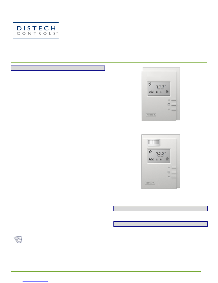
Figure 1-1:
Allure EC-Smart-Vue, Allure EC-Smart-Vue-H/-C/-CH
sensors
Figure 1-2:
Models equipped with a motion sensing window in the
upper left corner: Allure EC-Smart-Vue-M/-CM/-HM/-
CHM sensors
2. Cleaning
Clean the Allure EC-Smart-Vue sensors by polishing with a soft dry
cloth.
3. General Installation Requirements
For proper installation and subsequent operation of the Allure
EC-Smart-Vue sensors, pay special attention to the following
recommendations:
•
It is recommended that the sensor(s) be kept at room temperature
for at least 24 hours before installation to allow any condensation
that may have accumulated due to low temperature during
shipping/storage, to evaporate.
•
Upon unpacking the product, inspect the contents of the carton for
shipping damages.
Do not install damaged sensors.
•
The device is designed to operate under environmental conditions
that are specified in its datasheet.
Hardware Installation Guide
Allure
™
EC-Smart-Vue Series:
Communicating Space temperature sensors with a communication jack, setpoint
adjustment, occupancy override, and fan speed selection
2/10
•
Ensure proper ventilation of device and avoid areas where
corroding, deteriorating or explosive vapors, fumes or gases may
be present.
•
Do not drop the sensor or subject it to physical shock.
•
If the device is used and/or installed in a manner not specified by
Distech Controls, the functionality and the protection provided by
the device may be impaired.
•
To ensure reading accuracy, handle sensor with care and avoid
installing on a vibrating surface.
Make connections to the Allure EC-Smart-Vue sensors last.
Yanking the cable while it is attached to the sensor can
damage the connector.
Any type of modification to any Distech Controls product will
void the product’s warranty.
Take reasonable precautions to prevent electrostatic
discharges to the device when installing, servicing or
operating it. Discharge accumulated static electricity by
touching one’s hand to a securely grounded object before
working with the device.
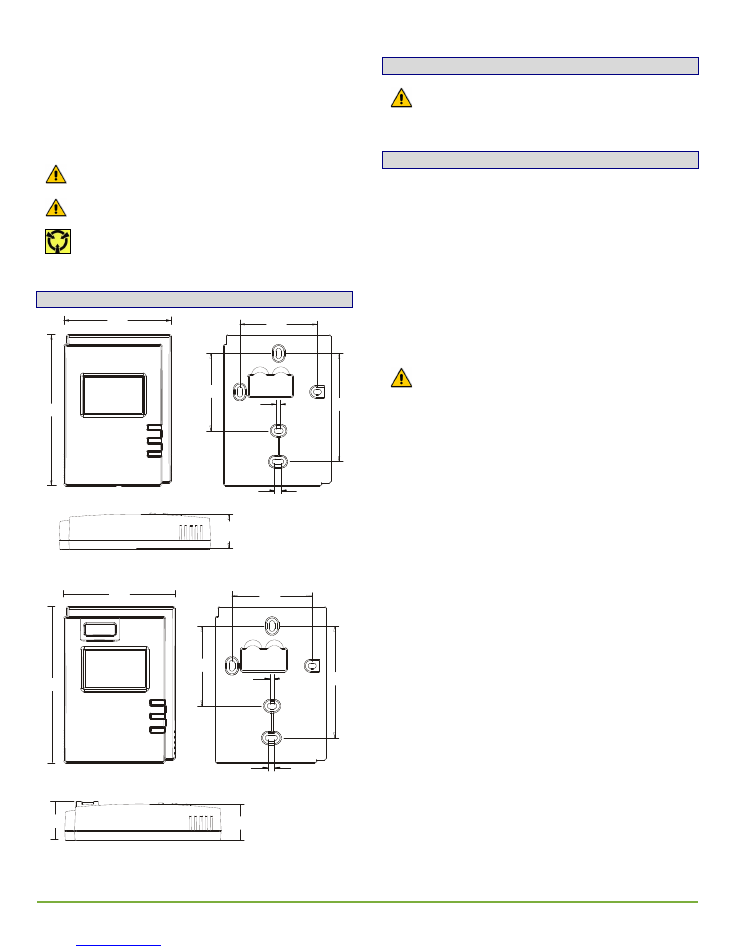
4. Device Dimensions
Mounting Base Plate Shown Detached
Unit Legend:
inches (mm)
3.29
(83.57)
4.62
(117.27)
2.37
(60.30)
2.36
(60.00)
3.31
(84.00)
0.12
(3.00)
0.20
(4.98)
1.06
(26.81)
Figure 4-1:
Front view, back plate, and side view for models
WITHOUT motion sensor
Unit Legend:
inches (mm)
Mounting Base Plate Shown Detached
3.29
(83.57)
2.37
(60.30)
4.62
(117.27)
2.36
(60.00)
0.12
(3.00)
3.31
(84.00)
0.20
(4.98)
1.15
(28.84)
1.06
(26.81)
Figure 4-2:
Front view, back plate, and side view for models WITH
motion sensor. Note the motion detection window in
the upper left corner of the sensor.
5. General Wiring Recommendations
Turn off power before any kind of servicing.
•
All wiring must comply with national and local electrical codes.
6. Mounting Instructions
The Allure EC-Smart-Vue sensors have been specially designed for
easy installation. However, certain conditions apply when choosing a
suitable location for the device:
•
The device should not be installed on an exterior wall.
•
The device should not be installed near a heat source.
•
The device should not be installed near an air discharge grill.
•
The device should not be installed in a place where it can be
affected by the sun.
•
Install the device in an area that provides proper device ventilation.
Nothing must restrain air circulation to the device.
•
Models equipped with a motion sensor should be installed in a
location and at a height where people will pass in front of it, within
its detection zone. See the datasheet for this information.
•
Models equipped with a CO
2
sensor must be used in spaces that
are periodically unoccupied (e.g. during evening or nighttime
hours).
The Allure EC-Smart-Vue sensor has not been designed for
outdoor use.
Installation Procedure
1. Remove the security screw from the device (Figure 7-1).
2. Open the device by pressing in the two (2) tabs on the bottom of
the device with a flat screwdriver and pulling the bottom side of the
front plate out.
3. Pull all cables 6” (15 cm) out of the wall, and insert them through
the central hole of the back plate.
4. Align the back plate with the wall and mark the location of the
mounting holes on the wall. Make sure to orient the proper side of
the back plate facing upwards.
5. Remove the back plate and drill holes in the wall if necessary.
6. Install anchors in the wall if necessary.
7. Make sure that the mounting surface is flat and clean.
8. Screw the back plate onto the wall. Do not over tighten.
9. Plug the wire(s) into the connector(s).
10. Gently push excess wiring back into the wall.
11. Set any jumpers. See
Figure 10-1
.
12. Reattach the front plate and make sure it clips tightly into place.
Start by hooking the top in place, and then clip the bottom edge
into place.
13. Install security screw.
3/10
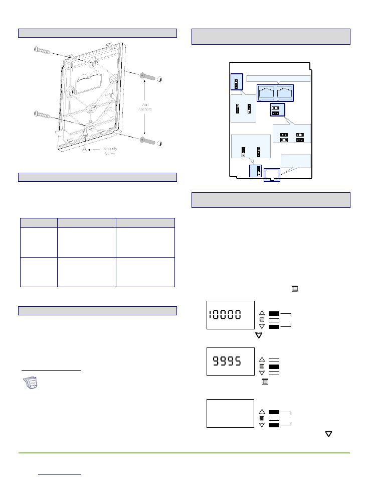
7. Device Components
Figure 7-1:
Mounting an Allure EC-Smart-Vue
8. Supported Quantity
Each controller supports a maximum number of Allure EC-Smart-Vue
sensors. The Subnet ID of all Allure EC-Smart-Vue sensors must be
set to be within the shown addressing range.
Table 8-1:
Number of Allure EC-Smart-Vue sensors supported by
controller model
Series
Maximum Number of Allure
EC-Smart-Vue sensors
Permitted Subnet ID
Addressing Range
ECB-VAV Series
ECL-VAV Series
ECB-103
ECL-103
ECB-203
ECL-203
4
1
1 to 4
ECB-300
ECL-300
ECB-400 Series
ECL-400 Series
ECB-600 Series
ECL-600 Series
12
1
1 to 12
1
A controller can support a maximum of two (2) Allure EC-Smart-Vue models
equipped with a CO
2
sensor. The remaining connected Allure EC-Smart-Vue
models must be without a CO
2
sensor.
9. About the Allure EC-Smart-Vue CO
2
Sensors
The Allure EC-Smart-Vue-C/-CM/-CH/-CHM are factory calibrated to
accurately read CO
2
concentration levels at sea level. When these
Allure EC-Smart-Vue sensors are used in locations where the
elevation is greater than 500ft (152m) above sea level, you must set
the Elevation input of the corresponding ComSensor block in
EC-
gfx
Program to the current location’s elevation to obtain the most
accurate readings.
For more information, refer to the Inputs and Outputs section in the
EC-
gfx
Program User Guide
Under normal conditions, an Allure EC-Smart-Vue sensor
with CO
2
sensor will reach its operational accuracy after 25
hours of continuous operation on condition that it was
exposed to ambient air reference levels of 400 ppm ±10
ppm CO
2
.
10. Connector and Configuration Jumper Location
and Identification
Allure EC-Smart-Vues sensors have the following onsite configurable
jumpers.
ON
EOL
OFF
Allure EC-Smart-Vue
Front Cover, Interior View
BAC
LON
Local Area Network Type
Jumper
BACnet
L
ON
W
ORKS
3.5 mm (1/8”) Local
Area Network Access
Jack
Pass-Through Subnetwork RJ-45 Connectors
D
E
J11
J6
J18
PIR
LED
PIR LED
Motion Detection
Models Only
Disabled
Enabled
Subnetwork End of Line
Enabled
Disabled
Figure 10-1: Connector and Jumper
Locations
11. Setting Up the Allure EC-Smart-Vue with Motion
Sensors
The following procedure describes how to commission and test the
Allure EC-Smart-Vue sensors equipped with motion sensors as well as
adjust the motion sensitivity (Allure EC-Smart-Vue-M/-CM/-HM/-CHM).
1. Connect an Allure EC-Smart-Vue with motion sensor to the
controller with a Cat 5e patch cable.
2. After a 30-second warm-up period, if movement is detected, the
motion sensor light will turn on.
3. To test the sensor functionality, aim the sensor in the direction you
want to detect motion and walk at a normal pace across the typical
detection zone and verify that the sensor light turns on. The light
will turn on and after 2 seconds of non-movement, the motion
sensor light will turn off.
4. Now to set the motion sensitivity, on the Allure EC-Smart-Vue
sensor, press and hold the
Menu
button
for 5 seconds to enter
the password menu. 10000 is shown on the display.
Screen timeout: 15 sec
OR
5. Press the down button
to set the number to 9995 (this is the
default password).
Screen timeout: 15 sec
6. Press the
Menu
button
to submit the password. Upon
submitting the password, the
GEN CFG
menu appears on the
display.
Screen timeout: 30 sec
OR
7. To enter the
GEN CFG
submenu, press the down button
once.
PASSW
PASSW
GEN C
4/10
8. Press the
Menu
button
several times until
MOTION
SENSITIVITY
appears on the display. The current motion
sensitivity level is shown.
Screen timeout: 30 sec
OR
9. Use the up and down buttons
to set the motion sensitivity
level to 0 (low), 1 (medium - typical default setting), or 2 (high). The
default and recommended level of sensitivity is medium (1) and
should typically work with all installations. This setting should not
be changed unless for some reason you are experiencing false
detections, then a low sensitivity (0) setting may be used, or if
working with larger room installations a high sensitivity (2) setting
can be used.
10. Press the Menu button
once to apply the value.
11. Press and hold the Menu button
for 5 seconds to exit the
configuration menu.
The motion indicator LED provides a visual confirmation of
motion detection. By default, the indicator (PIR LED jumper)
is enabled. If you wish to disable it, set jumper J18 to
Disabled. See
Figure 10-1.
12. About the Subnetwork Bus
The ECB-600 and ECL-600 controllers use the subnetwork bus to
support the ECx-4XX Series IO Extension Modules through 2-wire
shielded cable.
All Distech Controls ECB series and ECL series controllers also use
the subnetwork bus to support one or more Allure EC-Smart-Vue
sensor(s) using standard structural cabling. See
Table 8-1
. For the
Allure EC-Smart-Vue sensor, the subnetwork bus also extends the
LAN to the Allure EC-Smart-Vue room sensor to provide convenient
network access for maintenance and troubleshooting purposes.
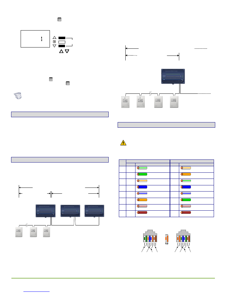
13. Subnetwork Bus Total Length
The total maximum length of all subnetwork buses, including both the
length of the Allure EC-Smart-Vue subnetwork bus and the ECx-4XX
subnetwork bus is 1000 ft (300 m). The maximum length of the Allure
EC-Smart-Vue subnetwork bus is 600 ft (180 m). The maximum length
of the ECx-4XX subnetwork bus is 1000 ft (300 m).
ECx-400 Sub-Network Bus
EC-Smart-Vue Sub-Network Bus – Cat 5e
Cable with RJ-45 Connectors
Typical ECB-600 /
ECL-600 Controller
Typical ECx-400 Series Extension I/O Modules –
For use with an ECB-600 / ECL-600 Series
Controller Only
ECx-400 Sub-Network Bus:
300 m (1 000 ft) Maximum
EC-Smart-Vue Sub-Network
Bus: 180 m (600 ft) Maximum
Sub-Network Bus Total Length: 300 m (1 000 ft) Maximum
2-Wire Shielded Cable
Figure 13-1 Subnetwork Bus Overview Showing the Allure
EC-Smart-Vue Subnetwork Bus and the ECx-4XX
Subnetwork Bus
A controller can support a maximum of two (2) Allure EC-Smart-Vue
models equipped with a CO
2
sensor; the remaining connected models
must be without a CO
2
sensor. For instance, if the subnetwork can
consist of 12 Allure EC-Smart-Vue sensors in all, then 10 sensor
models will be without a CO
2
sensor and the other two (2) will be
equipped with a CO
2
sensor. To ensure proper functioning, it is
recommended to distribute the sensors throughout the subnetwork.
ECx-400 Sub-Network Bus
Cat 5e Cable with RJ-45 Connectors
Typical ECB/ECL-600 Controller
EC-Smart-Vue Sub-Network
Sub-Network Bus Total Length: 300 m (1 000 ft) Maximum
10x...
2x...
Bus: 180 m (600 ft) Maximum
Figure 13-2 Allure EC-Smart-Vue Sensors Subnetwork Length and
Distribution
14. Connection Cable
Connect the Allure EC-Smart-Vue sensor to the controller with a
standard Cat 5e Ethernet patch cable fitted with RJ-45 connectors.
If you make your own patch cable, use Cat 5e cable and crimp
the RJ-45 connectors at both ends of the cable either as
T568A or T568B.
Table 14-1: T568A and T568B Terminations for an RJ-45
Connector
Pin T568A (at both cable ends)
T568B (at both cable ends)
Pair
Color
Pair
Color
1
3
white/green stripe
2
white/orange stripe
2
3
green solid
2
orange solid
3
2
white/orange stripe
3
white/green stripe
4
1
blue solid
1
blue solid
5
1
white/blue stripe
1
white/blue stripe
6
2
orange solid
3
green solid
7
4
white/brown stripe
4
white/brown stripe
8
4
brown solid
4
brown solid
The final result of a crimped RJ-45 connector is shown graphically
below.
T568A
T568B
Stripe Solid
1 2 3 4 5 6 7 8
1 2 3 4 5 6 7 8
Pair 3 Pair 1 Pair 2 Pair 4
Pair 2 Pair 1 Pair 3 Pair 4
Key:
Figure 14-1: T568A and T568B Crimp Wire Sequence for an RJ-45
Connector
MOTIO
5/10
Figure 14-2: Pins on RJ-45 Jack Face
Patch cables fitted with connectors supplied by Distech Controls are
wired as T568B.
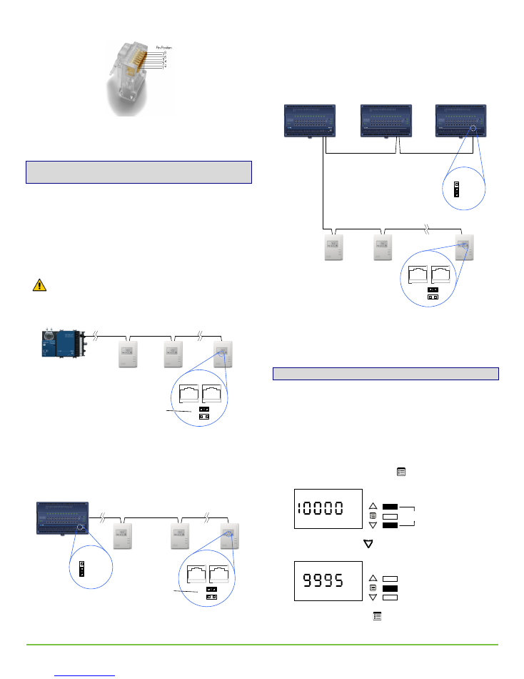
15. Subnetwork Bus Topology and EOL
Terminations
Only a daisy-chain topology is acceptable for the EC-Smart-Vue
subnetwork Bus. T-connections are not allowed.
When one or more Allure EC-Smart-Vue sensors are installed with an
ECB-VAV Series, ECB-103, ECB-203, ECB-300, ECB-400 Series,
ECL-VAV Series, ECL-103, ECL-203, ECL-300, or ECL-400 Series
Controller, only the EOL terminations of the last Allure EC-Smart-Vue
sensor are set to ON. All other Allure EC-Smart-Vue sensors must
have their EOL terminations set to OFF. The controller must be the first
devices on the bus as the EOL termination in these devices are
permanently enabled.
A controller can support a maximum of two (2) Allure
EC-Smart-Vue models equipped with a CO
2
sensor. The
remaining connected Allure EC-Smart-Vue models must be
without a CO
2
sensor.
EC-Smart-Vue Sub-Network Bus – Cat 5e Cable with RJ-45 Connectors
EOL set to ON
at the last
sensor at the
end of the Bus
ON
EOL
OFF
Controller Series:
· ECB-VAVS / ECB-VAV
· ECB-103
· ECB-203
· ECB-300
· ECB-400
· ECL-VAVS / ECL-VAV
· ECL-103
· ECL-203
· ECL-300
· ECL-400
Figure 15-1: Setting the EOL Terminations on the Allure
EC-Smart-Vue Subnetwork Bus for non ECB-600 or
ECL-600 series controllers
When one or more Allure EC-Smart-Vue sensors are installed with an
ECB-600 / ECL-600 (without an ECx-4XX IO Extension Module), only
the EOL terminations on the ECB-600 / ECL-600 and the last Allure
EC-Smart-Vue sensor are set to ON. All other Allure EC-Smart-Vue
sensors must have their EOL terminations set to OFF.
Figure 15-2: Setting the EOL Terminations on the Allure
EC-Smart-Vue Subnetwork Bus for ECB-600 or
ECL-600 Series controllers
When ECx-400 Series IO Extension Modules are installed with an
ECB-600 / ECL-600 Series controller and with Allure EC-Smart-Vue
sensor(s), only the EOL terminations on the last ECx-400 Series IO
Extension Module and the last EC Smart Vue are set to ON. All other
ECx-400 Series IO Extension Modules and Allure EC-Smart-Vue
models must have their EOL terminations set to OFF.
Figure 15-3: Setting the EOL Terminations when Allure
EC-Smart-Vue Sensors are used with ECx-400 Series
IO Extension Modules
ECx-400 Series devices and Allure EC-Smart-Vue sensors are factory-
set with the EOL set to OFF by default.
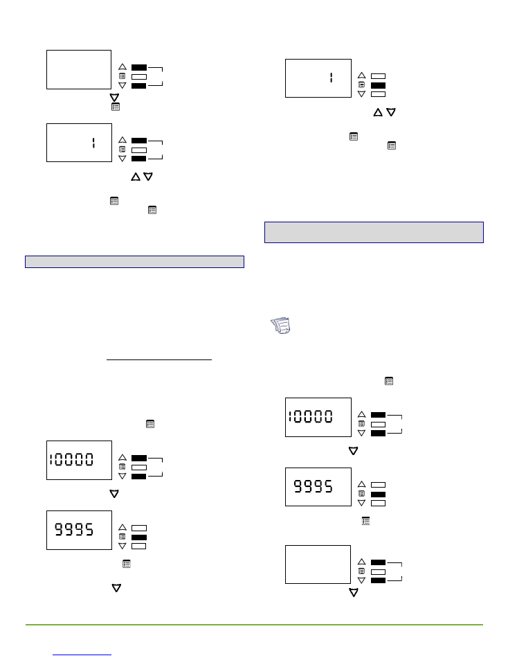
16. Setting the Allure EC-Smart-Vue Subnet ID
Controllers can be commissioned with an Allure EC-Smart-Vue sensor.
The default Subnet ID for an Allure EC-Smart-Vue is 1. To commission
a controller, the Allure EC-Smart-Vue’s Subnet ID must be set to 1. If
the Allure EC-Smart-Vue’s Subnet ID has been set to another value
(for example, the display flashes error code 1 with the Bell icon when
the Allure EC-Smart-Vue sensor is connected to a controller for
commissioning), change the Subnet ID to 1 as follows:
1. Connect an Allure EC-Smart-Vue sensor to the controller with a Cat
5e patch cable. Wait for the Bell icon and the number 1 to flash on
the display.
2. Press and hold the Menu button
for 5 seconds to enter the
password menu. 10000 is shown on the display.
Screen timeout: 15 sec
OR
3. Press the down button
to set the number to 9995 (this is the
default password).
Screen timeout: 15 sec
4. Press the
Menu
button
to submit the password. Upon
submitting the password, the
GEN CFG
menu appears on the
display.
EC-Smart-Vue Sub-Network Bus – Cat 5e Cable with RJ-45 Connectors
Controller Series:
· ECB-600
· ECL-600
EOL set to ON
at the last
sensor at the
end of the Bus
ON
EOL
OFF
For ECB-600 / ECL-600, set the
Sub-Network EOL to ON
EOL OFF
EOL ON
Typical ECB-600 /
ECL-600 Controller
Typical ECx-4XX Series Extension I/O Modules – For use
with an ECB-600 / ECL-600 Series Controller Only
ECx-4XX Sub-Network Bus
2-Wire Shielded
EOL OFF
•
Last daisy-chained EC-Smart-Vue:
EOL Jumper is ON
•
All other EC-Smart-Vue:
EOL Jumpers are OFF
For ECx-4XX:
EC-Smart-Vue Sub-Network Bus – Cat 5e
Cable with RJ-45 Connectors
•
Last daisy-chained EC-Smart-Vue:
EOL Jumper is ON
•
All other EC-Smart-Vue:
EOL Jumpers are OFF
For EC-Smart-Vue:
ON
EOL
OFF
EOL ON
PASSW
PASSW
6/10
Screen timeout: 30 sec
OR
5. Press the down button
once to enter the
GEN CFG
submenu.
6. Press the Menu button
several times until SUBNET ID appears
on the display. The current controller’s Subnet ID is shown.
Screen timeout: 30 sec
OR
7. Use the up and down buttons
to set the controller’s Subnet
ID to
1
.
Tip
: Hold down either the up or down button to fast-
advance the display value.
8. Press the Menu button
once.
9. Press and hold the Menu button
for 5 seconds to exit the
configuration menu.
The Allure EC-Smart-Vue sensor can now be used to go from one
controller to the next for commissioning purposes.
17. Commissioning Controllers
To commission a controller with a MAC Address DIP switch located on
the faceplate or under the cover in the case of an ECB-VAV Series
controller, first set the DIP switch to 0 (all off). When using an Allure
EC-Smart-Vue sensor for commissioning a controller (before code is
downloaded to the controller from EC-
gfx
Program), connect an Allure
EC-Smart-Vue sensor to the controller with its Subnet ID set to 1. (see
Section 16
).
For ECB-VAV and ECL-VAV Series controllers, commissioning can be
used to perform application selection if needed. Applications are pre-
loaded programs that enable the ECB-VAV and ECL-VAV to control a
typical VAV box. See the Pre-Loaded Application User Guide for more
information.
For ECB Series controllers only, during commissioning, the Allure
EC-Smart-Vue sensor is used to set the controller’s BACnet
®
MAC
Address. Set the connected ECB Series controller’s MAC Address as
follows:
1. Connect an Allure EC-Smart-Vue sensor to the controller with a Cat
5e patch cable. Wait for the display to show the room temperature.
2. Press and hold the Menu button
for 5 seconds to enter the
password menu. 10000 is shown on the display.
Screen timeout: 15 sec
OR
3. Use the down button
to set the number to 9995 (this is the
default password).
Screen timeout: 15 sec
4. Press the
Menu
button
to submit the password. Upon
submitting the password, the
GEN CFG
menu appears on the
display.
5. Press the down button
once to enter the
GEN CFG
submenu.
The
MAC ADDRESS
menu is shown with the current controller’s
BACnet MAC Address.
Screen timeout: 30 sec
6. Use the up and down buttons
to set the controller’s MAC
Address. Only addresses from 1 to 127 are recommended to be
used.
7. Press the Menu button
once to apply the value.
8. Press and hold the Menu button
for 5 seconds to exit the
configuration menu.
Once the controller’s communications network is operational, the
controller can be programmed with EC-
gfx
Program. For each Allure
EC-Smart-Vue sensor, set its Subnet ID number to the block number
of its associated ComSensor block in EC-
gfx
Program. This is done in
the Allure EC-Smart-Vue’s
GEN CFG
menu under
SUBNET ID
. The
range of valid Allure EC-Smart-Vue Subnet IDs is shown in Table 8-1.
18. Setting the BAUD
Rate (optional – BACnet
controllers only)
By default, the BAUD rate for the controller is set to automatically
detect the current communication BAUD rate of the connected BACnet
MS/TP network (AUTO). This is the preferred setting for a controller.
However, at least one controller on the BACnet MS/TP network data
bus must have its BAUD rate set. The preference is to set the building
controller’s BAUD rate (if present). Otherwise, set the BAUD rate on
one controller that will set the BAUD rate for all other controllers (to act
as the master for setting the BAUD rate).
When the Baud rate is set to AUTO, the controller cannot
initiate any communication until it has detected the baud rate
of the BACnet MS/TP network. If all controllers on the
BACnet MS/TP network are set to AUTO, then all controllers
will not communicate.
Set the connected controller’s BAUD rate as follows:
1. Connect an Allure EC-Smart-Vue sensor to the controller with a Cat
5e patch cable. Wait for the display to show the room temperature.
2. Press and hold the Menu button
for 5 seconds to enter the
password menu. 10000 is shown on the display.
Screen timeout: 15 sec
OR
3. Use the down button
to set the number to 9995 (this is the
default password).
Screen timeout: 15 sec
4. Press the
Menu
button
to submit the password. Upon
submitting the password, the
GEN CFG
menu appears on the
display.
Screen timeout: 30 sec
OR
5. Press the down button
once to enter the
GEN CFG
submenu.
PASSW
PASSW
MAC A
PASSW
PASSW
GEN C
SUBNE
GEN C
7/10
6. Use the Menu button
several times until
BAUD RATE
appears
on the display. The current controller’s BAUD rate is shown.
Screen timeout: 30 sec
7. Use the up and down buttons
to set the controller’s Baud
rate. The
AUTO
setting detects and uses the current baud rate
being used by the BACnet MS/TP network.
8. Press the Menu button
once to apply the value.
9. Press and hold the Menu button
for 5 seconds to exit the
configuration menu.
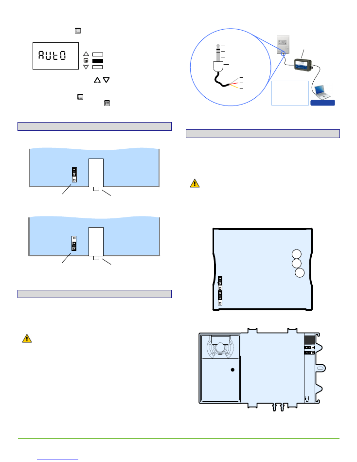
19. Set the LAN Type
Set the BAC/LON jumper for the type LAN in use: BAC for a BACnet
network, LON for a L
ON
W
ORKS
network.
Figure 19-1: BAC/LON Jumper Set to the BAC (BACnet) Position
Figure 19-2: BAC/LON Jumper: Set to the LON (L
ON
W
ORKS
)
Position
20. BACnet Network Access from the Sensor
To temporarily access the BACnet MS/TP LAN for commissioning and
maintenance purposes, connect a BACnet MS/TP Adaptor to the audio
plug port located on the lower edge of the Allure EC-Smart-Vue
sensor. Wire a standard
⅛
” (3.5 mm) three-conductor stereo jack as
shown below.
The BACnet MS/TP Adaptor must have an electrically-isolated
RS-485 port. Otherwise a ground path from the BACnet
network will be made through the computer that will disrupt
BACnet network communications.
To BACnet MS/TP
Adaptor
NET+
NET-
Shield
LAN Access
Connector
EC-Net Pro
- Temporary
Commissioning and
Maintenance
Connection
- No EOL Resistors are
Necessary
BACnet MS/TP Adaptor
with Isolated RS-485 Port
Cable Supplied with
BACnet MS/TP Adaptor
NET+ (White)
NET- (Red)
Shield (bare)
Figure 20-1:
⅛
” (3.5 mm) Stereo Jack Connection for a Portable
Router
21. L
ON
W
ORKS
Network Access from the Sensor
For commissioning and maintenance purposes, the L
ON
W
ORKS
network is optionally available from the Allure EC-Smart-Vue audio
plug port. By setting the two (2)
Net to Subnet Port Settings
jumpers
inside the ECL series controller to
Enable
will connect the main
L
ON
W
ORKS
network to the Allure EC-Smart-Vue subnetwork Cat 5e
cable.
Recommendation
: Only a limited number of controllers on a
L
ON
W
ORKS
network segment should have their
Net to Subnet
Port Settings
jumpers enabled. Enabling too many Allure EC-
Smart-Vue sensors with network access may cause network
communication issues. If there are any network communication
problems, refer to Section 22.
The Cat 5e cable length is restricted by the maximum allowable
subnetwork bus length (see
Subnetwork Bus Total Length
). The
standard
Net to Subnet Port Settings
jumper setting is
Disable
.
Enable
Disable
Enable
Disable
Net to Subnet
Port Settings
Figure 21-1: ECL series controller: Net to Subnet Port Settings
Jumpers
E
D
Enable
Disable
Net to Subnet
Port Settings
Figure 21-2: ECL-VAV series controller: Net to Subnet Port Settings
Jumpers
BAC
LON
3.5 mm (1/8
”) Network
Access Jack
Network Type
Jumper
BAC
LON
3.5 mm (1/8
”) Network
Access Jack
Network Type
Jumper
BAUD
8/10
Controller
Bus Network Topology: 22AWG (0.65mm) Unshielded Twisted Pair Network Cable
Cat5e communications cable:
·
Allure EC-Smart-Vue Sub-Network Bus
·
L
ON
W
ORKS
Network when Net to Subnet
Port Settings jumpers are Enabled
E
D
Enable
Disable
For One or Two
Controllers ONLY:
Standard Net to
Subnet Port
Settings:
DISABLED - this
is the factory
default setting
Allure EC-Smart-Vue
Net to Subnet Port Settings
Optionally Enabled
Figure 21-3:
L
ON
W
ORKS
Network: Bus Topology
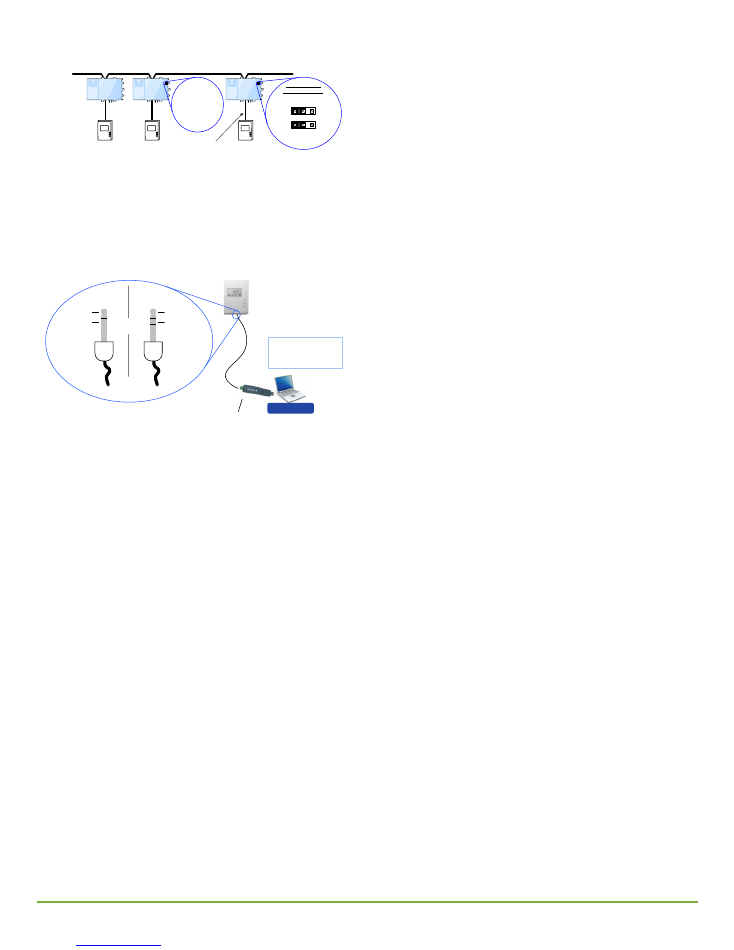
To temporarily access the L
ON
W
ORKS
LAN for commissioning and
maintenance purposes, connect a L
ON
W
ORKS
network interface to the
audio plug port located on the lower edge of the Allure EC-Smart-Vue
sensor. Wire a standard
⅛
” (3.5 mm) three-conductor (stereo jack) or
two-conductor (mono jack) as shown below.
EC-Net Pro
- Temporary
Commissioning and
Maintenance
Connection
LON USB Network
Interface
To LON USB
Network Interface
LON1
LON2
LAN Access
Connector
LON1
LON2
Mono Jack
Stereo Jack
OR
LAN Access
Connector
Figure 21-4:
⅛
” (3.5 mm) Stereo or Mono Jack Connection for a
L
ON
W
ORKS
Network Interface

9/10
22. Troubleshooting Guide
Allure EC-Smart-Vue screen is blank & back light is off
Is the Allure EC-Smart-Vue sensor connected to the controller?
Verify that the Allure EC-Smart-Vue sensor is connected to the controller and that the patch
cables are plugged into the connectors. Refer to
Installation Procedure
for more information.
Is power being supplied to the controller?
There may be no power being supplied from the controller. Check if the controller has power
or if the controller’s internal fuses have blown or tripped.
Is the cable connected to the controller and Allure EC-Smart-Vue
sensor?
Verify wiring.
Was the patch cable made onsite?
Verify that the RJ-45 crimp connectors were installed on the cable correctly. See
Connection
Cable
.
Allure EC-Smart-Vue screen is blank & back light is on for about 30 to 45 seconds – Normal Operation
Firmware upgrade in progress
Wait for the upgrade to complete. Do not disconnect the sensor from the controller as the
upgrade will restart once it is reconnected.
Device not communicating with controller
Is the address correctly set to a unique address?
Each Allure EC-Smart-Vue sensor must be set to a unique address for each controller. See
Setting the Allure EC-Smart-Vue Subnet ID
.
Is the device too far from controller?
Verify the distance between the device and the controller. See
Subnetwork Bus Total Length
.
Is there a configuration problem?
With EC-
gfx
Program, check the configuration of the sensor; for example, is it enabled? Refer
to the EC-
gfx
Program User Guide for more information.
Have the subnetwork EOL settings been correctly set?
Only the last Allure EC-Smart-Vue sensor must have its EOL termination set to ON. See
Figure 15-1
and
Figure 15-2
. When one or more ECx-400 Series IO Extension modules are
connected to the controller, only the last ECx-400 must have its EOL termination set to ON.
See
Figure 15-3
.
Controller cannot communicate on the L
ON
W
ORKS
network
Too many Allure EC-Smart-Vue sensors are providing network access
Disable the
Net to Subnet Port Settings
jumpers on all controllers (for jumper location, see
Section
21
). If communications are re-established, re-enable only a few Allure EC-Smart-Vue
sensors to have network access.
Allure EC-Smart-Vue motion detector window indicator is always ON and the Motion output of the associated
ComSensor block always reads NULL in EC-
gfx
Program
Does the connected controller have Allure EC-Smart-Vue firmware
that supports the motion sensor?
When the Allure EC-Smart-Vue sensor is connected to a controller, its firmware is loaded
from the controller. In this case, the controller has an earlier version of Allure EC-Smart-Vue
firmware that does not support the motion sensor. To upgrade to the latest Allure
EC-Smart-Vue firmware, download the firmware from SmartInstaller and refer to the firmware
upgrade procedure in the EC-
gfx
Program User Guide.
The CO
2
output of the associated ComSensor block always reads NULL in EC-
gfx
Program
Does the connected controller have Allure EC-Smart-Vue firmware
that supports the CO
2
sensor?
When the Allure EC-Smart-Vue sensor is connected to a controller, its firmware is loaded
from the controller. In this case, the controller has an earlier version of Allure EC-Smart-Vue
firmware that does not support the CO
2
sensor. To upgrade to the latest Allure EC-Smart-Vue
firmware, download the firmware from SmartInstaller and refer to the firmware upgrade
procedure in the EC-
gfx
Program User Guide.
The CO
2
sensor readings are too high, too low, or inconsistent between sensors
Immediately after installing the Allure EC-Smart-Vue with CO
2
sensors,
are the CO
2
sensor readings incoherent?
If the CO
2
sensor readings seem unusual or show inconsistencies between sensors in the
same building right after installation, the following reasons should be taken into consideration:
•
Concentration levels in each space may be different
•
The installer may have unintentionally blown into the sensor while installing it.
•
The sensor may have been dropped or mishandled during shipment causing a minor
shift in the original factory calibration.
The recommendation is to allow up to 14 days of operation (without power interruptions) for
the sensor to calibrate itself according to its new environment.
Error Code Interpretation
Clock icon flashing for 15 seconds
Cannot communicate
with controller.
Wait for the communication link to the controller to be established.
After 15 seconds: Flashing error code 1 with Bell icon
Verify wiring
Verify that all Allure EC-Smart-Vue’s Subnet IDs are unique for
this controller. See
Setting the Allure EC-Smart-Vue Subnet ID
.
Flashing error code 2 with Bell icon
Invalid configuration.
In EC-
gfx
Program, resynchronize the code with the controller.
Contact Distech Controls Customer Support.
Flashing error code 3 with Bell icon
Allure EC-Smart-Vue
sensor is not properly
configured in the
controller
With EC-
gfx
Program, check the configuration of the sensor, for
example, is it enabled? Refer to the EC-
gfx
Program User Guide
for more information.

Total Quality Commitment
All Distech Controls product lines are built to meet rigorous quality standards. Distech Controls is an ISO 9001 registered
company.
©, Distech Controls Inc. 2010. All rights reserved.
While all efforts have been made to verify the accuracy of information in this manual, Distech Controls is not responsible for damages or claims arising from the use of
this manual. Persons using this manual are assumed to be trained HVAC specialist / installers and are responsible for using the correct wiring procedures and
maintaining safe working conditions with fail-safe environments. Distech Controls reserves the right to change, delete or add to the information in this manual at any
time without notice.
Distech Controls, the Distech Controls logo, Open-to-Wireless, Innovative Solutions for Greener Buildings, ECO-Vue, and Allure are trademarks of Distech Controls Inc.
Echelon, LON, LonTalk, L
ON
M
ARK
and L
ON
W
ORKS
are registered trademarks of Echelon Corporation registered in the United States and other countries. BACnet is a
registered trademark of ASHRAE.
10/10
*05DI-HIECSMV-20*
05DI-HIECSMV-20