Full Text Searchable PDF User Manual

___________________________ Installing instructions
______________________________
Issued by: PM approved by DG Rev.07 date 01/03/16 pag. 1/12
Aprilia Dorsoduro 750 09-16
Aprilia Shiver 07-16 (RapidBike Evo only)
INSTALLATION INSTRUCTIONS

___________________________ Installing instructions
______________________________
Issued by: PM approved by DG Rev.07 date 01/03/16 pag. 2/12
Attention: For a correct RB feeding voltage, check the operation of all motorbike
electrical system components (lights, fuse, stock connectors, etc.).
1. Turn off the engine.
2. Remove the main seat and the fuel tank.
____________________________ Injection section ___________________________
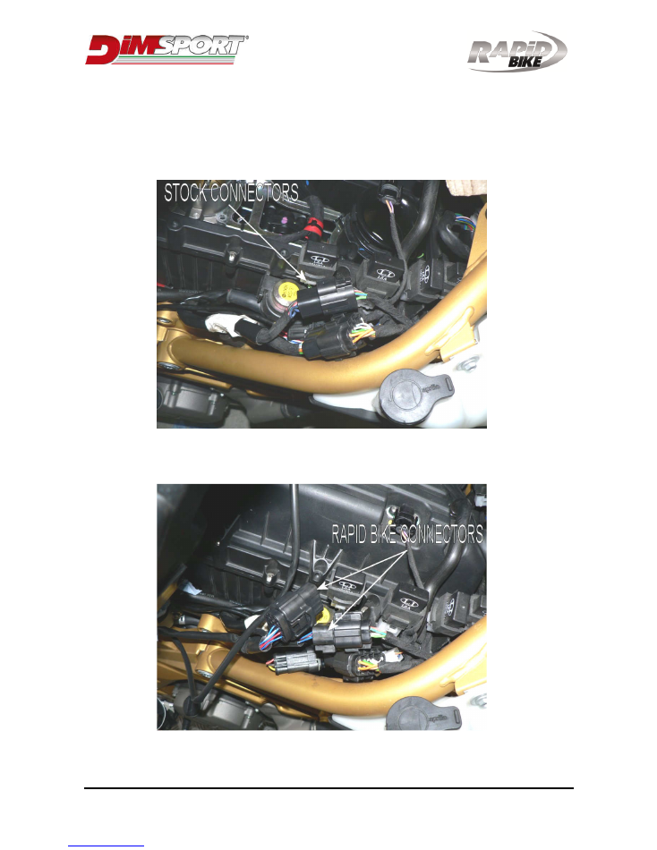
3. Locate and disconnect the 2 way connector of the front cylinder’s injector.
4. Connect Rapid Bike connectors marked as INJECTOR 1 in-line of the stock
harness.
5. Locate and disconnect the 2 way connector of the rear cylinder’s injector.
6. Connect Rapid Bike connectors marked as INJECTOR 2 in-line of the stock
harness.
WARNING: In case the harness has one couple of 6-way connectors marked as
“INJECTORS”, then follow the instructions at the bottom of this manual (Page 9).
___________________________ Installing instructions
______________________________
Issued by: PM approved by DG Rev.07 date 01/03/16 pag. 3/12
_____________________________ T.P.S. section ______________________________
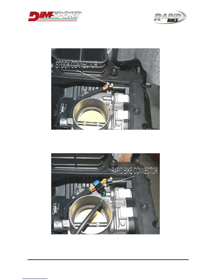
7. Locate and disconnect the black six-way connector placed into the airbox (Fig.1).
Fig.1
8. Connect the green wire of the RAPID BIKE wiring harness to the wire located in
central position on the top row of the stock connector (Pin #4), using the posi-tap
connector (Fig.2).
Fig.2
9. Connect the stock connector in the original position.
___________________________ Installing instructions
______________________________
Issued by: PM approved by DG Rev.07 date 01/03/16 pag. 4/12
________________________ Crankshaft sensor section ________________________
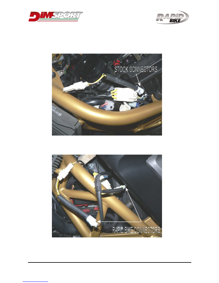
10. Locate and disconnect the white two-way connector on the front-left side of the
motorbike (Fig.3).
Fig.3
11. Connect the connectors of RAPID BIKE wiring harness to the stock connectors
(Fig.4).
Fig.4
___________________________ Installing instructions
______________________________
Issued by: PM approved by DG Rev.07 date 01/03/16 pag. 5/12
___________________________ O2 sensor section ____________________________
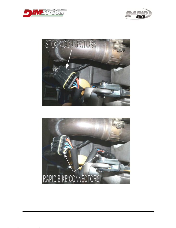
15. Locate and disconnect the 4 pin black connector of the o2 sensor (Fig.5).
Fig.5
12. Connect the Rapid Bike connectors in-line with the stock connectors (Fig.6).
Fig.6
___________________________ Installing instructions
______________________________
Issued by: PM approved by DG Rev.07 date 01/03/16 pag. 6/12
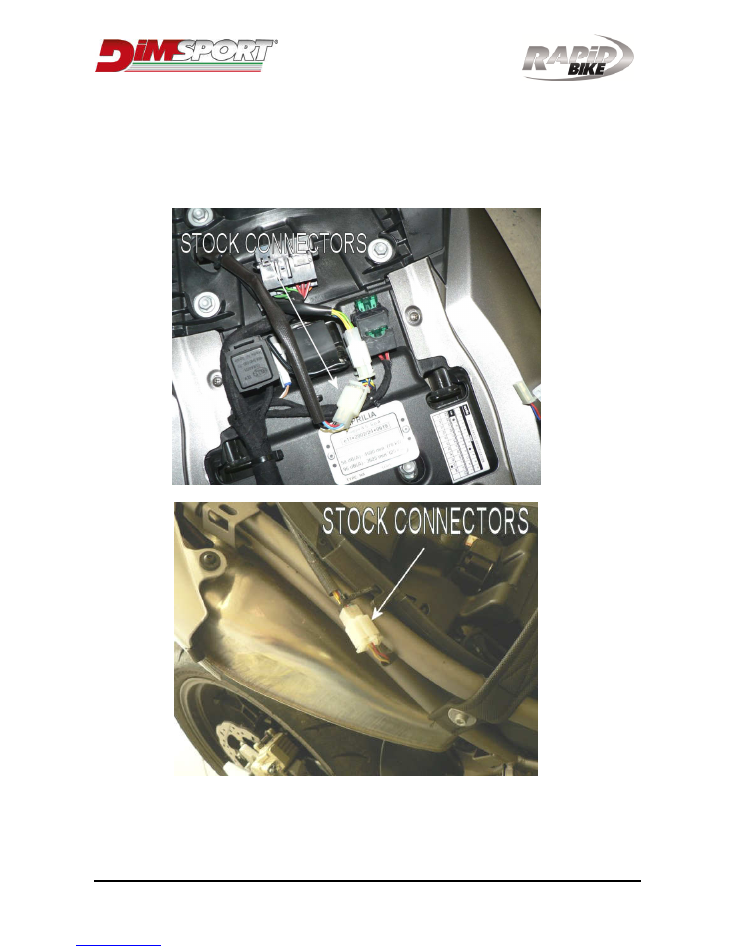
_________________________ Feeding voltage section _________________________
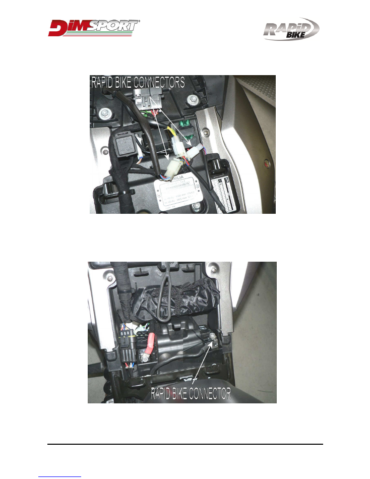
13. SHIVER: Locate and disconnect the white 3 pin connector on the back of the
underseat compartment (Fig.7A).
DORSODURO: Locate and disconnect the white 6 pin connector on the right side of
the underseat compartment (Fig.7B)
Fig.7A
Fig.7B
___________________________ Installing instructions
______________________________
Issued by: PM approved by DG Rev.07 date 01/03/16 pag. 7/12
14. Connect the Rapid Bike connectors in-line with the stock connectors. Use the
provided adapter to perform the connection on Dorsoduro model (Fig.8).
Fig.8
15. Connect the eyelet from the RAPID BIKE wiring harness to the negative pole of the
battery (Fig.9).
Fig.9
___________________________ Installing instructions
______________________________
Issued by: PM approved by DG Rev.07 date 01/03/16 pag. 8/12
_____________________________ Final Section_____________________________
14. Connect the Rapid Bike wiring harness to the RAPID BIKE module.
15. Check the correct connection of all the connectors.
16. Fix the RAPID BIKE control unit to the motorbike in the underseat compartment.
17. Place back the fuel tank and the seat.
__________________________ Accessories section ___________________________
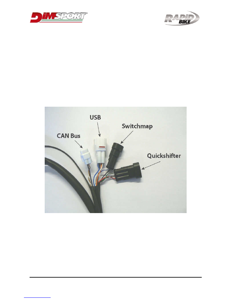
The Rapid Bike wiring has four other connections for the accessories:
-
Connection for the quickshifter sensor (black 3 pin connector)
-
Connection for the handlebar switchmap (black 2 pin connector)
-
Connection for the CAN Bus interface (white 3 pin connector)
-
Connection for the USB interface (white 4 pin connector)
___________________________ Installing instructions
______________________________
Issued by: PM approved by DG Rev.07 date 01/03/16 pag. 9/12
Notes:
1. Locate and disconnect the black six-way connector on the front-right side of the
motorbike.
2. Connect the black six-way connector of the RAPID BIKE wiring harness to the stock
connector.

___________________________ Installing instructions
______________________________
Issued by: PM approved by DG Rev.07 date 01/03/16 pag. 10/12
Notes:
…………………………………………………………………………………………………………
…………………………………………………………………………………………………………
…………………………………………………………………………………………………………
…………………………………………………………………………………………………………
…………………………………………………………………………………………………………
…………………………………………………………………………………………………………
…………………………………………………………………………………………………………
…………………………………………………………………………………………………………
…………………………………………………………………………………………………………
…………………………………………………………………………………………………………
…………………………………………………………………………………………………………
…………………………………………………………………………………………………………
…………………………………………………………………………………………………………
…………………………………………………………………………………………………………
…………………………………………………………………………………………………………
…………………………………………………………………………………………………………
…………………………………………………………………………………………………………
…………………………………………………………………………………………………………
…………………………………………………………………………………………………………
…………………………………………………………………………………………………………
…………………………………………………………………………………………………………
…………………………………………………………………………………………………………
…………………………………………………………………………………………………………

___________________________ Installing instructions
______________________________
Issued by: PM approved by DG Rev.07 date 01/03/16 pag. 11/12
Notes:
…………………………………………………………………………………………………………
…………………………………………………………………………………………………………
…………………………………………………………………………………………………………
…………………………………………………………………………………………………………
…………………………………………………………………………………………………………
…………………………………………………………………………………………………………
…………………………………………………………………………………………………………
…………………………………………………………………………………………………………
…………………………………………………………………………………………………………
…………………………………………………………………………………………………………
…………………………………………………………………………………………………………
…………………………………………………………………………………………………………
…………………………………………………………………………………………………………
…………………………………………………………………………………………………………
…………………………………………………………………………………………………………
…………………………………………………………………………………………………………
…………………………………………………………………………………………………………
…………………………………………………………………………………………………………
…………………………………………………………………………………………………………
…………………………………………………………………………………………………………
…………………………………………………………………………………………………………
…………………………………………………………………………………………………………
…………………………………………………………………………………………………………
___________________________ Installing instructions
______________________________
Issued by: PM approved by DG Rev.07 date 01/03/16 pag. 12/12